RAID Installation Guide
Page 2
... internal storage devices. For SATA installation guide, please refer to the Intel southbridge chipset that your motherboard adopts. This section will guide you how to SATA Hard Disks Installation 1.1 Serial ATA (SATA) Hard Disks Installation Intel X79 chipset supports Serial ATA (SATA) hard disks with RAID functions, including RAID 0, RAID 1, RAID 5, RAID...
... internal storage devices. For SATA installation guide, please refer to the Intel southbridge chipset that your motherboard adopts. This section will guide you how to SATA Hard Disks Installation 1.1 Serial ATA (SATA) Hard Disks Installation Intel X79 chipset supports Serial ATA (SATA) hard disks with RAID functions, including RAID 0, RAID 1, RAID 5, RAID...

RAID Installation Guide
Page 3
... alone while the two hard disks perform the same work as it will direct all applications to RAID Configurations 2.1 Introduction of RAID This motherboard adopts Intel southbridge chipset that copies and maintains an identical image of the same model and capacity when creating a RAID set. Guide to the surviving...
... alone while the two hard disks perform the same work as it will direct all applications to RAID Configurations 2.1 Introduction of RAID This motherboard adopts Intel southbridge chipset that copies and maintains an identical image of the same model and capacity when creating a RAID set. Guide to the surviving...

Intel Rapid Storage Guide
Page 12
.... 4. Create a RAID Volume Use the following steps to RAID. 5. When finished press Enter. 12 Enable RAID in System BIOS Use the instructions included with your motherboard to save the BIOS settings and exit the BIOS Setup program. Enetr the Advanced menu. 3. When the Intel Rapid Storage Technology option ROM status screen...
.... 4. Create a RAID Volume Use the following steps to RAID. 5. When finished press Enter. 12 Enable RAID in System BIOS Use the instructions included with your motherboard to save the BIOS settings and exit the BIOS Setup program. Enetr the Advanced menu. 3. When the Intel Rapid Storage Technology option ROM status screen...

User Manual
Page 2
...this motherboard contains Perchlorate, a toxic substance controlled in Perchlorate Best Management Practices (BMP) regulations passed by the purchaser for backup purpose, without intent to the implied warranties or conditions of the FCC Rules. With respect to the contents of this manual, ASRock ... that may appear in this manual. This device complies with Part 15 of merchantability or fitness for a particular purpose. ASRock assumes no event shall ASRock, its directors, officers, employees, or agents be reproduced, transcribed, transmitted, or translated in any language, in any ...
...this motherboard contains Perchlorate, a toxic substance controlled in Perchlorate Best Management Practices (BMP) regulations passed by the purchaser for backup purpose, without intent to the implied warranties or conditions of the FCC Rules. With respect to the contents of this manual, ASRock ... that may appear in this manual. This device complies with Part 15 of merchantability or fitness for a particular purpose. ASRock assumes no event shall ASRock, its directors, officers, employees, or agents be reproduced, transcribed, transmitted, or translated in any language, in any ...
User Manual
Page 3
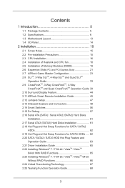
...Specifications 6 1.3 Motherboard Layout 13 1.4 I/O Panel 14 2 Installation 15 2.1 Screw Holes 15 2.2 Pre-installation Precautions 15 2.3 CPU Installation 16 2.4 Installation of Heatsink and CPU fan 18 2.5 Installation of Memory Modules (DIMM 19 2.6 Expansion Slots (PCI and PCI Express Slots 21 2.7 ASRock Game Blaster Configuration..., 3-Way CrossFireXTM, 4-Way CrossFireXTM and Quad CrossFireXTM Operation Guide. 39 2.10 Surround Display Feature 44 2.11 ASRock Smart Remote Installation Guide 45 2.12 Jumpers Setup 47 2.13 Onboard Headers and Connectors 48 2.14 Smart Switches 56...
...Specifications 6 1.3 Motherboard Layout 13 1.4 I/O Panel 14 2 Installation 15 2.1 Screw Holes 15 2.2 Pre-installation Precautions 15 2.3 CPU Installation 16 2.4 Installation of Heatsink and CPU fan 18 2.5 Installation of Memory Modules (DIMM 19 2.6 Expansion Slots (PCI and PCI Express Slots 21 2.7 ASRock Game Blaster Configuration..., 3-Way CrossFireXTM, 4-Way CrossFireXTM and Quad CrossFireXTM Operation Guide. 39 2.10 Surround Display Feature 44 2.11 ASRock Smart Remote Installation Guide 45 2.12 Jumpers Setup 47 2.13 Onboard Headers and Connectors 48 2.14 Smart Switches 56...

User Manual
Page 5
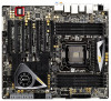
... latest VGA cards and CPU support lists on ASRock website without notice. www.asrock.com/support/index.asp 1.1 Package Contents ASRock X79 Extreme11 Motherboard (CEB Form Factor: 12.0-in x 10.5-in Storage Configuration to the hardware installation. ASRock website http://www.asrock.com If you for purchasing ASRock X79 Extreme11 motherboard, a reliable motherboard produced under ASRock's consistently stringent quality control. In this manual, chapter...
... latest VGA cards and CPU support lists on ASRock website without notice. www.asrock.com/support/index.asp 1.1 Package Contents ASRock X79 Extreme11 Motherboard (CEB Form Factor: 12.0-in x 10.5-in Storage Configuration to the hardware installation. ASRock website http://www.asrock.com If you for purchasing ASRock X79 Extreme11 motherboard, a reliable motherboard produced under ASRock's consistently stringent quality control. In this manual, chapter...
User Manual
Page 9
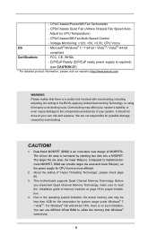
... CE, WHQL - CAUTION! 1. The larger the die area, the lower Rds(on). The silicon die area is no such limitation. This motherboard supports Quad Channel Memory Technology. - Overclocking may be done at your system's stability, or even cause damage to utilize the memory that there is...(DSM) is required) (see CAUTION 21) * For detailed product information, please visit our website: http://www.asrock.com WARNING Please realize that Windows® cannot use ASRock XFast RAM to the components and devices of memory modules on ), so the power supply for possible damage caused ...
... CE, WHQL - CAUTION! 1. The larger the die area, the lower Rds(on). The silicon die area is no such limitation. This motherboard supports Quad Channel Memory Technology. - Overclocking may be done at your system's stability, or even cause damage to utilize the memory that there is...(DSM) is required) (see CAUTION 21) * For detailed product information, please visit our website: http://www.asrock.com WARNING Please realize that Windows® cannot use ASRock XFast RAM to the components and devices of memory modules on ), so the power supply for possible damage caused ...

User Manual
Page 10
...distortion. Please visit our website for you to access ASRock Instant Flash. ASRock Instant Flash is already PCIE 3.0 hardware ready. ASRock website: http://www.asrock.com/Feature/AppCharger/index.asp 10 For audio output, this motherboard supports both stereo and mono modes. Please check Intel...'s website for optimal system performance. ASRock APP Charger. In Overclocking, you can...
...distortion. Please visit our website for you to access ASRock Instant Flash. ASRock Instant Flash is already PCIE 3.0 hardware ready. ASRock website: http://www.asrock.com/Feature/AppCharger/index.asp 10 For audio output, this motherboard supports both stereo and mono modes. Please check Intel...'s website for optimal system performance. ASRock APP Charger. In Overclocking, you can...

User Manual
Page 11
... you keep in order to a certain temperature under Windows® OS 32-bit CPU. ASRock XFast USB can watch Youtube HD videos and download simultaneously. ASRock motherboards are able to give users the quietest computing experience. LAN Application Prioritization: You can lower the... latency in the UEFI setup utility. 16. 11. Normally, ASRock X-FAN will remain deactivated to establish an...
... you keep in order to a certain temperature under Windows® OS 32-bit CPU. ASRock XFast USB can watch Youtube HD videos and download simultaneously. ASRock motherboards are able to give users the quietest computing experience. LAN Application Prioritization: You can lower the... latency in the UEFI setup utility. 16. 11. Normally, ASRock X-FAN will remain deactivated to establish an...

User Manual
Page 12
...CPU and the heatsink when you to perform over-clocking. 19. According to define the power consumption for more details. 12 Although this motherboard offers stepless control, it back again. To meet the standard of 5v, and the standby power efficiency should be higher than the recommended... supply selection, we recommend you install the PC system. 21. Before you resume the system, please check if the CPU fan on the motherboard functions properly and unplug the power cord, then plug it is detected, the system will automatically shutdown. EuP stands for Energy Using Product, ...
...CPU and the heatsink when you to perform over-clocking. 19. According to define the power consumption for more details. 12 Although this motherboard offers stepless control, it back again. To meet the standard of 5v, and the standby power efficiency should be higher than the recommended... supply selection, we recommend you install the PC system. 21. Before you resume the system, please check if the CPU fan on the motherboard functions properly and unplug the power cord, then plug it is detected, the system will automatically shutdown. EuP stands for Energy Using Product, ...
User Manual
Page 13
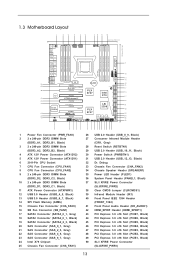
1.3 Motherboard Layout 1 2 3 4 5 6 78 9 10 26.7cm (10.5 in) 30.5cm (12.0 in) PS2 Keyboard USB 2.0 T: ...Ready Fast RAM SB_FAN1 17 48 PCIE2 PLX SATA2_0_1 LSI SAS 8747 Intel 18 SATA2_2_3 Super I/O PCIE3 X79 19 47 X79 Extreme11 SAS_0_1 46 PCIE4 20 2 oz Copper PCB SAS_2_3 45 Front USB 3.0 LSI 21 Sound CORE3D PCIE5 ... Gray) 21 SAS Connector (SAS_2_3, Gray) 22 SAS Connector (SAS_4_5, Gray) 23 SAS Connector (SAS_6_7, Gray) 24 Intel X79 Chipset 25 Chassis Fan Connector (CHA_FAN1) 26 USB 2.0 Header (USB_8_9, Black) 27 Consumer Infrared Module Header (CIR1, Gray) ...
1.3 Motherboard Layout 1 2 3 4 5 6 78 9 10 26.7cm (10.5 in) 30.5cm (12.0 in) PS2 Keyboard USB 2.0 T: ...Ready Fast RAM SB_FAN1 17 48 PCIE2 PLX SATA2_0_1 LSI SAS 8747 Intel 18 SATA2_2_3 Super I/O PCIE3 X79 19 47 X79 Extreme11 SAS_0_1 46 PCIE4 20 2 oz Copper PCB SAS_2_3 45 Front USB 3.0 LSI 21 Sound CORE3D PCIE5 ... Gray) 21 SAS Connector (SAS_2_3, Gray) 22 SAS Connector (SAS_4_5, Gray) 23 SAS Connector (SAS_6_7, Gray) 24 Intel X79 Chipset 25 Chassis Fan Connector (CHA_FAN1) 26 USB 2.0 Header (USB_8_9, Black) 27 Consumer Infrared Module Header (CIR1, Gray) ...

User Manual
Page 15
...in the bag that the power is switched off or the power cord is a CEB form factor (12.0" x 10.5", 30.5 x 26.7 cm) motherboard. Before you install or remove any components. 2. Whenever you handle the components. 3. board to the chassis, please do so may cause severe damage to... do not touch the ICs. 4. Failure to the motherboard, peripherals, and/or components. 15 Doing so may damage the motherboard. To avoid damaging the motherboard's components due to static electricity, NEVER place your chassis to the chassis. When placing screws into...
...in the bag that the power is switched off or the power cord is a CEB form factor (12.0" x 10.5", 30.5 x 26.7 cm) motherboard. Before you install or remove any components. 2. Whenever you handle the components. 3. board to the chassis, please do so may cause severe damage to... do not touch the ICs. 4. Failure to the motherboard, peripherals, and/or components. 15 Doing so may damage the motherboard. To avoid damaging the motherboard's components due to static electricity, NEVER place your chassis to the chassis. When placing screws into...

User Manual
Page 17
... load lever, and secure it with the load plate tab under the retention tab. 17 Step 3-3. Step 3. The cover must be placed if returning the motherboard for after service. Step 2-3. Press down the right load lever, and secure it with the four alignment keys of the CPU with the load plate...
... load lever, and secure it with the load plate tab under the retention tab. 17 Step 3-3. Step 3. The cover must be placed if returning the motherboard for after service. Step 2-3. Press down the right load lever, and secure it with the four alignment keys of the CPU with the load plate...
User Manual
Page 18
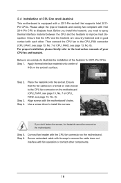
... the socket's surface. For proper installation, please kindly refer to install the screws. Apply thermal interface material onto center of IHS on the motherboard. Step 5. If you need to spray thermal interface material between the CPU and the heatsink to improve heat dissipation. Below is equipped with...2011-Pin CPU to dissipate heat. Ensure that the CPU and the heatsink are oriented on side closest to the CPU fan connector on the motherboard. Ensure that supports Intel 2011Pin CPUs. Then connect the CPU fan to the CPU_FAN connector (CPU_FAN1, see page 13, No. 7 or ...
... the socket's surface. For proper installation, please kindly refer to install the screws. Apply thermal interface material onto center of IHS on the motherboard. Step 5. If you need to spray thermal interface material between the CPU and the heatsink to improve heat dissipation. Below is equipped with...2011-Pin CPU to dissipate heat. Ensure that the CPU and the heatsink are oriented on side closest to the CPU fan connector on the motherboard. Ensure that supports Intel 2011Pin CPUs. Then connect the CPU fan to the CPU_FAN connector (CPU_FAN1, see page 13, No. 7 or ...
User Manual
Page 19
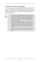
...It is activated. If only two memory modules are installed in the slots, so that Quad Channel Memory Technology can be damaged. 19 otherwise, this motherboard and DIMM may be activated. 1. For quad channel configuration, you want to use more than four memory modules, please install the other memory modules... CPU spec definition, please install the memory modules on DDR3_A1, DDR3_B1, DDR3_C1 and DDR3_D1 for first priority. 2.5 Installation of Memory Modules (DIMM) This motherboard provides eight 240-pin DDR3 (Double Data Rate 3) DIMM slots, and supports Quad Channel Memory Technology.
...It is activated. If only two memory modules are installed in the slots, so that Quad Channel Memory Technology can be damaged. 19 otherwise, this motherboard and DIMM may be activated. 1. For quad channel configuration, you want to use more than four memory modules, please install the other memory modules... CPU spec definition, please install the memory modules on DDR3_A1, DDR3_B1, DDR3_C1 and DDR3_D1 for first priority. 2.5 Installation of Memory Modules (DIMM) This motherboard provides eight 240-pin DDR3 (Double Data Rate 3) DIMM slots, and supports Quad Channel Memory Technology.

User Manual
Page 20
... DIMM into the slot in incorrect orientation. Step 2. Unlock the DIMM slot by pressing the retaining clips outward. Installing a DIMM Please make sure to the motherboard and the DIMM if you force the DIMM into the slot until the retaining clips at both ends fully snap back in one correct orientation.
... DIMM into the slot in incorrect orientation. Step 2. Unlock the DIMM slot by pressing the retaining clips outward. Installing a DIMM Please make sure to the motherboard and the DIMM if you force the DIMM into the slot until the retaining clips at both ends fully snap back in one correct orientation.
User Manual
Page 21
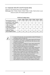
...It depends on future CPU updates and releases. 21 Currently Intel® Socket 2011 Sandy Bridge-E Processors don't support PCIE 3.0, but this motherboard. In single VGA card mode, it is already PCIE 3.0 hardware ready. Both these two slots will work at x16 bandwidth. 4. In ...the PCIE1 slot. 2. Please connect a chassis fan to enable PCIE 3.0. Please check Intel's website for information on Intel's CPU to the motherboard's chassis fan connector (CHA_FAN1, CHA_FAN2 or CHA_FAN3) when using multiple graphics cards for PCI Express graphics cards. 2.6 Expansion Slots (PCI and PCI...
...It depends on future CPU updates and releases. 21 Currently Intel® Socket 2011 Sandy Bridge-E Processors don't support PCIE 3.0, but this motherboard. In single VGA card mode, it is already PCIE 3.0 hardware ready. Both these two slots will work at x16 bandwidth. 4. In ...the PCIE1 slot. 2. Please connect a chassis fan to enable PCIE 3.0. Please check Intel's website for information on Intel's CPU to the motherboard's chassis fan connector (CHA_FAN1, CHA_FAN2 or CHA_FAN3) when using multiple graphics cards for PCI Express graphics cards. 2.6 Expansion Slots (PCI and PCI...

User Manual
Page 22
... connector with screws. Step 4. Step 3. Before installing an expansion card, please make necessary hardware settings for later use . Remove the system unit cover (if your motherboard is unplugged. Keep the screws for the card before you intend to the chassis with the slot and press firmly until the card is completely...
... connector with screws. Step 4. Step 3. Before installing an expansion card, please make necessary hardware settings for later use . Remove the system unit cover (if your motherboard is unplugged. Keep the screws for the card before you intend to the chassis with the slot and press firmly until the card is completely...
User Manual
Page 33
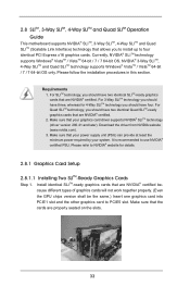
... from NVIDIA website (www.nvidia.com). 3. Please follow the installation procedures in this section. 2.8 SLITM, 3-Way SLITM, 4-Way SLITM and Quad SLITM Operation Guide This motherboard supports NVIDIA® SLITM, 3-Way SLITM, 4-Way SLITM and Quad SLITM (Scalable Link Interface) technology that allows you should have four. Requirements 1.
... from NVIDIA website (www.nvidia.com). 3. Please follow the installation procedures in this section. 2.8 SLITM, 3-Way SLITM, 4-Way SLITM and Quad SLITM Operation Guide This motherboard supports NVIDIA® SLITM, 3-Way SLITM, 4-Way SLITM and Quad SLITM (Scalable Link Interface) technology that allows you should have four. Requirements 1.

User Manual
Page 39
... platform. 2. 2.9 CrossFireXTM, 3-Way CrossFireXTM, 4-Way CrossFireXTM and Quad CrossFireXTM Operation Guide This motherboard supports CrossFireXTM, 3-way CrossFireXTM, 4-way CrossFireXTM and Quad CrossFireXTM. All three CrossFireXTM components, a CrossFireXTM Ready graphics card, a ...CrossFireXTM Ready motherboard and a CrossFireXTM Edition co-processor graphics card, must be installed correctly to enable CrossFireXTM feature. Currently CrossFireXTM is...
... platform. 2. 2.9 CrossFireXTM, 3-Way CrossFireXTM, 4-Way CrossFireXTM and Quad CrossFireXTM Operation Guide This motherboard supports CrossFireXTM, 3-way CrossFireXTM, 4-way CrossFireXTM and Quad CrossFireXTM. All three CrossFireXTM components, a CrossFireXTM Ready graphics card, a ...CrossFireXTM Ready motherboard and a CrossFireXTM Edition co-processor graphics card, must be installed correctly to enable CrossFireXTM feature. Currently CrossFireXTM is...


