User Manual
Page 13
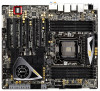
1.3 Motherboard Layout 1 2 3 4 5 6 78 9 10 26.7cm (10.5 in) 30.5cm (12.0 in) PS2 Keyboard USB ...Fast RAM SB_FAN1 17 48 PCIE2 PLX SATA2_0_1 LSI SAS 8747 Intel 18 SATA2_2_3 Super I/O PCIE3 X79 19 47 X79 Extreme11 SAS_0_1 46 PCIE4 20 2 oz Copper PCB SAS_2_3 45 Front USB 3.0 LSI 21 Sound CORE3D ...x 240-pin DDR3 DIMM Slots (DDR3_A1, DDR3_B1, Black) 3 2 x 240-pin DDR3 DIMM Slots (DDR3_A2, DDR3_B2, Black) 4 ATX 12V Power Connector (ATX12V2) 5 ATX 12V Power Connector (ATX12V1) 6 2011-Pin CPU Socket 7 CPU Fan Connector (CPU_FAN1) 8 CPU Fan Connector (CPU_FAN2) 9 2 x...
1.3 Motherboard Layout 1 2 3 4 5 6 78 9 10 26.7cm (10.5 in) 30.5cm (12.0 in) PS2 Keyboard USB ...Fast RAM SB_FAN1 17 48 PCIE2 PLX SATA2_0_1 LSI SAS 8747 Intel 18 SATA2_2_3 Super I/O PCIE3 X79 19 47 X79 Extreme11 SAS_0_1 46 PCIE4 20 2 oz Copper PCB SAS_2_3 45 Front USB 3.0 LSI 21 Sound CORE3D ...x 240-pin DDR3 DIMM Slots (DDR3_A1, DDR3_B1, Black) 3 2 x 240-pin DDR3 DIMM Slots (DDR3_A2, DDR3_B2, Black) 4 ATX 12V Power Connector (ATX12V2) 5 ATX 12V Power Connector (ATX12V1) 6 2011-Pin CPU Socket 7 CPU Fan Connector (CPU_FAN1) 8 CPU Fan Connector (CPU_FAN2) 9 2 x...

User Manual
Page 45
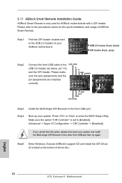
... , pin 1-5) and the CIR header. Execute ASRock's support CD and install the CIR Driver. (It is listed at the bottom of ASRock Smart Remote. Please refer to enter the BIOS... Install the Multi-Angle CIR Receiver to the USB_PWR USB 2.0 header (as below for ASRock motherboards with a CIR header. Make sure the option "CIR Controller" is only used for the quick ...installation and usage of driver list.) 45 Step5. 2.11 ASRock Smart Remote Installation Guide ASRock Smart Remote is set to the USB 2.0 header on your ASRock motherboard. Find the CIR header located next to [Enabled]. (Advanced...
... , pin 1-5) and the CIR header. Execute ASRock's support CD and install the CIR Driver. (It is listed at the bottom of ASRock Smart Remote. Please refer to enter the BIOS... Install the Multi-Angle CIR Receiver to the USB_PWR USB 2.0 header (as below for ASRock motherboards with a CIR header. Make sure the option "CIR Controller" is only used for the quick ...installation and usage of driver list.) 45 Step5. 2.11 ASRock Smart Remote Installation Guide ASRock Smart Remote is set to the USB 2.0 header on your ASRock motherboard. Find the CIR header located next to [Enabled]. (Advanced...
User Manual
Page 53
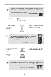
...Connected 3-Pin Fan Installation (3-pin CPU_FAN2) (see p.13, No. 8) ATX Power Connector 12 24 (24-pin ATXPWR1) (see p.13, No. 4) 4 5 Please connect ATX 12V power supplies to these connectors. 1 5 1 Though this motherboard provides 8-pin ATX 12V power connectors, it can still work successfully even without the fan ... ATX12V1) (see p.13, No. 5) 4 (8-pin ATX12V2) 8 (see p.13, No. 11) 1 13 Please connect an ATX power supply to Pin 1-3. Though this motherboard provides 4-Pin CPU fan (Quiet Fan) support, the 3-Pin CPU fan still can work if you plan to connect the 3-Pin ...
...Connected 3-Pin Fan Installation (3-pin CPU_FAN2) (see p.13, No. 8) ATX Power Connector 12 24 (24-pin ATXPWR1) (see p.13, No. 4) 4 5 Please connect ATX 12V power supplies to these connectors. 1 5 1 Though this motherboard provides 8-pin ATX 12V power connectors, it can still work successfully even without the fan ... ATX12V1) (see p.13, No. 5) 4 (8-pin ATX12V2) 8 (see p.13, No. 11) 1 13 Please connect an ATX power supply to Pin 1-3. Though this motherboard provides 4-Pin CPU fan (Quiet Fan) support, the 3-Pin CPU fan still can work if you plan to connect the 3-Pin ...

Quick Installation Guide
Page 2
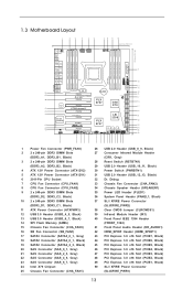
...) 36 System Panel Header (PANEL1, Black) 10 2 x 240-pin DDR3 DIMM Slots 37 SLI / XFIRE Power Connector (DDR3_D1, DDR3_C1, Black) (SLI/XFIRE_PWR2) 11 ATX Power Connector (ATXPWR1) 38 Clear CMOS Jumper (CLRCMOS1) 12 USB 3.0 Header (USB3_4_5, Black) 39 Infrared Module Header (IR1) 13 USB 3.0 Header (USB3_6_7, Black) ...Gray) 48 PCI Express 3.0 x16 Slot (PCIE2, Black) 23 SAS Connector (SAS_6_7, Gray) 49 PCI Express 3.0 x16 Slot (PCIE1, Black) 24 Intel X79 Chipset 50 SLI / XFIRE Power Connector 25 Chassis Fan Connector (CHA_FAN1) 2 (SLI/XFIRE_PWR1) X79 Extreme11 Motherboard English
...) 36 System Panel Header (PANEL1, Black) 10 2 x 240-pin DDR3 DIMM Slots 37 SLI / XFIRE Power Connector (DDR3_D1, DDR3_C1, Black) (SLI/XFIRE_PWR2) 11 ATX Power Connector (ATXPWR1) 38 Clear CMOS Jumper (CLRCMOS1) 12 USB 3.0 Header (USB3_4_5, Black) 39 Infrared Module Header (IR1) 13 USB 3.0 Header (USB3_6_7, Black) ...Gray) 48 PCI Express 3.0 x16 Slot (PCIE2, Black) 23 SAS Connector (SAS_6_7, Gray) 49 PCI Express 3.0 x16 Slot (PCIE1, Black) 24 Intel X79 Chipset 50 SLI / XFIRE Power Connector 25 Chassis Fan Connector (CHA_FAN1) 2 (SLI/XFIRE_PWR1) X79 Extreme11 Motherboard English
Quick Installation Guide
Page 6
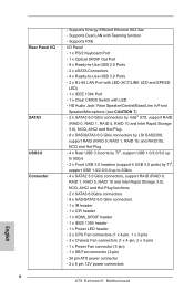
... /O SATA3 USB3.0 Connector 6 - HD Audio Jack: Rear Speaker/Central/Bass/Line in/Front Speaker/Microphone (see CAUTION 7) - 2 x SATA3 6.0 Gb/s connectors by Intel® X79, support RAID (RAID 0, RAID 1, RAID 5, RAID 10 and Intel Rapid Storage 3.0), NCQ, AHCI and Hot Plug - 8 x SAS/SATA3 6.0 Gb/s connectors by LSI SAS2308, ... Power LED header - 2 x CPU Fan connectors (1 x 4-pin, 1 x 3-pin) - 3 x Chassis Fan connectors (1 x 4-pin, 2 x 3-pin) - 1 x Power Fan connector (3-pin) - 1 x SB Fan connector (3-pin) - 24 pin ATX power connector - 2 x 8 pin 12V power connectors X79 Extreme11 Motherboard
... /O SATA3 USB3.0 Connector 6 - HD Audio Jack: Rear Speaker/Central/Bass/Line in/Front Speaker/Microphone (see CAUTION 7) - 2 x SATA3 6.0 Gb/s connectors by Intel® X79, support RAID (RAID 0, RAID 1, RAID 5, RAID 10 and Intel Rapid Storage 3.0), NCQ, AHCI and Hot Plug - 8 x SAS/SATA3 6.0 Gb/s connectors by LSI SAS2308, ... Power LED header - 2 x CPU Fan connectors (1 x 4-pin, 1 x 3-pin) - 3 x Chassis Fan connectors (1 x 4-pin, 2 x 3-pin) - 1 x Power Fan connector (3-pin) - 1 x SB Fan connector (3-pin) - 24 pin ATX power connector - 2 x 8 pin 12V power connectors X79 Extreme11 Motherboard
Quick Installation Guide
Page 42
...and install the Multi-Angle CIR Receiver to the USB 2.0 header (as below for ASRock motherboards with a CIR header. Enter Windows. Step5. Please refer to the USB 2.0 header on your ASRock motherboard. Connect the front USB cable to the other front USB port then try again.... Driver. (It is listed at the bottom of ASRock Smart Remote. 2.11 ASRock Smart Remote Installation Guide ASRock Smart Remote is only used for the quick installation and usage of driver list.) English 42 X79 Extreme11 Motherboard GND IRTX IRRX ATX+5VSB Step3. Make sure the option "CIR Controller...
...and install the Multi-Angle CIR Receiver to the USB 2.0 header (as below for ASRock motherboards with a CIR header. Enter Windows. Step5. Please refer to the USB 2.0 header on your ASRock motherboard. Connect the front USB cable to the other front USB port then try again.... Driver. (It is listed at the bottom of ASRock Smart Remote. 2.11 ASRock Smart Remote Installation Guide ASRock Smart Remote is only used for the quick installation and usage of driver list.) English 42 X79 Extreme11 Motherboard GND IRTX IRRX ATX+5VSB Step3. Make sure the option "CIR Controller...

Quick Installation Guide
Page 50
..., please plug your power supply along with Pin 1 and Pin 5. 8 5 4-Pin ATX 12V Power Supply Installation 4 1 50 X79 Extreme11 Motherboard English To use the 4-pin ATX power supply, please plug your power supply along with Pin 1 and Pin 13. 20-Pin ATX Power Supply Installation 1 13 ATX 12V Power Connector 8 (8-pin ATX12V1) (see p.2, No. 5) 4 (8-pin ATX12V2) 8 (see...
..., please plug your power supply along with Pin 1 and Pin 5. 8 5 4-Pin ATX 12V Power Supply Installation 4 1 50 X79 Extreme11 Motherboard English To use the 4-pin ATX power supply, please plug your power supply along with Pin 1 and Pin 13. 20-Pin ATX Power Supply Installation 1 13 ATX 12V Power Connector 8 (8-pin ATX12V1) (see p.2, No. 5) 4 (8-pin ATX12V2) 8 (see...
Quick Installation Guide
Page 189
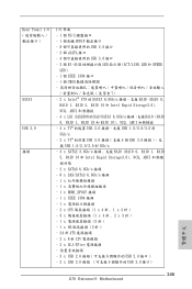
HDMI_SPDIF 헤더 1 개 - SB 1 개 (3 핀 ) - 24 핀 ATX 2 x 8 핀 ATX 12V 2 x SLI/XFIRE 189 X79 Extreme11 Motherboard 한국어 IEEE 1394 헤더 1 LED 헤더 1 개 - PXE 지원 I /O SATA3 USB 3.0 LAN &#... SPEED LED RJ-45 LAN 포트 - 1 개 IEEE 1394 포트 - 1 개 CMOS 7 참조 ) - Intel® X79 SATA3 6.0Gb/s 커넥터 2 RAID (RAID 0, RAID 1, RAID 5, RAID 10 및 Intel Rapid Storage 3.0), NCQ, AHCI 및 Hot Plug LSI ...
HDMI_SPDIF 헤더 1 개 - SB 1 개 (3 핀 ) - 24 핀 ATX 2 x 8 핀 ATX 12V 2 x SLI/XFIRE 189 X79 Extreme11 Motherboard 한국어 IEEE 1394 헤더 1 LED 헤더 1 개 - PXE 지원 I /O SATA3 USB 3.0 LAN &#... SPEED LED RJ-45 LAN 포트 - 1 개 IEEE 1394 포트 - 1 개 CMOS 7 참조 ) - Intel® X79 SATA3 6.0Gb/s 커넥터 2 RAID (RAID 0, RAID 1, RAID 5, RAID 10 및 Intel Rapid Storage 3.0), NCQ, AHCI 및 Hot Plug LSI ...
Quick Installation Guide
Page 201
...; CPU 1-3 1-3 3 (3 핀 CPU_FAN2) (2 8 ATX (24 핀 ATXPWR1) (2 11 12 24 ATX 1 13 24 핀 ATX 12 24 종래의 20 핀 ATX 20 핀 ATX Pin 1 과 Pin 13 20 핀 ATX 1 13 ATX 12V 8 (8 핀 ATX12V1) (2 5 4 (8 핀 ATX12V2) 8 (2 4 4 5 ATX 12V 1 5 1 8- 핀 ATX 12V 4- 핀 ATX 12V 하여 4- 핀 ATX 1 과 핀 5 8 5 4- 핀 ATX 12V 4 1 201 X79 Extreme11 Motherboard 한국어
...; CPU 1-3 1-3 3 (3 핀 CPU_FAN2) (2 8 ATX (24 핀 ATXPWR1) (2 11 12 24 ATX 1 13 24 핀 ATX 12 24 종래의 20 핀 ATX 20 핀 ATX Pin 1 과 Pin 13 20 핀 ATX 1 13 ATX 12V 8 (8 핀 ATX12V1) (2 5 4 (8 핀 ATX12V2) 8 (2 4 4 5 ATX 12V 1 5 1 8- 핀 ATX 12V 4- 핀 ATX 12V 하여 4- 핀 ATX 1 과 핀 5 8 5 4- 핀 ATX 12V 4 1 201 X79 Extreme11 Motherboard 한국어
Quick Installation Guide
Page 209
...;参照 ) - - ACPI 1.1 - ASRock Instant Flash ( 注意 9 参照 ) - ASRock APP 10 を参照 ) - ASRock XFast RAM ( 注意 14 を参照 ) - ASRock Internet Flash ( 注意 18 を参照 ) - ASRock U-COP ( 注意 20 を参照 ) 日本語 209 X79 Extreme11 Motherboard SB x 1 (3 ピン ) - 24 ピン ATX - 2 x 8 ピン 12V...
...;参照 ) - - ACPI 1.1 - ASRock Instant Flash ( 注意 9 参照 ) - ASRock APP 10 を参照 ) - ASRock XFast RAM ( 注意 14 を参照 ) - ASRock Internet Flash ( 注意 18 を参照 ) - ASRock U-COP ( 注意 20 を参照 ) 日本語 209 X79 Extreme11 Motherboard SB x 1 (3 ピン ) - 24 ピン ATX - 2 x 8 ピン 12V...
Quick Installation Guide
Page 227
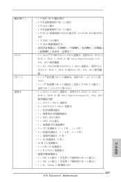
...和 SPEED LED) - 1 個 IEEE 1394 接口 - 1 個 CMOS 7) - 2 x Intel® X79 的 SATA3 6.0Gb/s RAID (RAID 0, RAID 1, RAID 5, RAID 10 和 Intel Rapid Storage 3.0), NCQ, AHCI 8 x ...2 x CPU 1 x 4 針 , 1 x 3 針 ) - 3 x 1 x 4 針 , 2 x 3 針 ) - 1 x 3 針 ) - 1 x SB 3 針 ) - 24 針 ATX 2 x 8 針 12V 2 x SLI/XFire 3 x USB 2.0 6 USB 2.0 接口 ) - 2 x USB 3.0 4 USB 3.0 接口 ) - 1 x Dr. Debug (7 段調試 LED) 227 X79 Extreme11 Motherboard 簡體中文
...和 SPEED LED) - 1 個 IEEE 1394 接口 - 1 個 CMOS 7) - 2 x Intel® X79 的 SATA3 6.0Gb/s RAID (RAID 0, RAID 1, RAID 5, RAID 10 和 Intel Rapid Storage 3.0), NCQ, AHCI 8 x ...2 x CPU 1 x 4 針 , 1 x 3 針 ) - 3 x 1 x 4 針 , 2 x 3 針 ) - 1 x 3 針 ) - 1 x SB 3 針 ) - 24 針 ATX 2 x 8 針 12V 2 x SLI/XFire 3 x USB 2.0 6 USB 2.0 接口 ) - 2 x USB 3.0 4 USB 3.0 接口 ) - 1 x Dr. Debug (7 段調試 LED) 227 X79 Extreme11 Motherboard 簡體中文
Quick Installation Guide
Page 245
...LINK LED 和 SPEED LED) - 1 個 IEEE 1394 接口 - 1 個 CMOS 7) - 2 x Intel® X79 的 SATA3 6.0Gb/s RAID (RAID 0, RAID 1, RAID 5, RAID 10 和 Intel Rapid Storage3.0), NCQ, AHCI 4 x LSI SAS2308 ...25509;頭 - 1 x 2 x CPU 1 x 4 針 , 1 x 3 針 ) - 3 x 1 x 4 針 , 2 x 3 針 ) - 1 x 3 針 ) - 1 x SB 3 針 ) - 24 針 ATX 2 x 8 針 12V 2 x SLI/XFire 3 x USB 2.0 6 USB 2.0 接口 ) - 2 x USB 3.0 4 USB 3.0 接口) 繁體中文 245 X79 Extreme11 Motherboard
...LINK LED 和 SPEED LED) - 1 個 IEEE 1394 接口 - 1 個 CMOS 7) - 2 x Intel® X79 的 SATA3 6.0Gb/s RAID (RAID 0, RAID 1, RAID 5, RAID 10 和 Intel Rapid Storage3.0), NCQ, AHCI 4 x LSI SAS2308 ...25509;頭 - 1 x 2 x CPU 1 x 4 針 , 1 x 3 針 ) - 3 x 1 x 4 針 , 2 x 3 針 ) - 1 x 3 針 ) - 1 x SB 3 針 ) - 24 針 ATX 2 x 8 針 12V 2 x SLI/XFire 3 x USB 2.0 6 USB 2.0 接口 ) - 2 x USB 3.0 4 USB 3.0 接口) 繁體中文 245 X79 Extreme11 Motherboard

