User Manual
Page 6
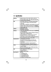
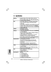
... slot) - 3 x PCI slots - Premium Blu-ray audio support - PCIE x1 Gigabit LAN 10/100/1000 Mb/s - Northbridge: Intel® X58 - Supports NVIDIA® Quad SLITM, 3-Way SLITM and SLITM - 7.1 CH Windows® VistaTM Premium Level HD Audio with 110dB dynamic range (ALC890...System Bus up to -Use USB 2.0 Ports 6 Supports Wake-On-LAN I /O - Supports Hyper-Threading Technology (see CAUTION 4) - Intel® Socket 1366 CoreTM i7 Processor Extreme Edition / CoreTM i7 Processor Supports Intel® Dynamic Speed Technology - Supports DDR3 2000(OC)/1866(OC)/1600(OC)/1333(OC)/ ...
... slot) - 3 x PCI slots - Premium Blu-ray audio support - PCIE x1 Gigabit LAN 10/100/1000 Mb/s - Northbridge: Intel® X58 - Supports NVIDIA® Quad SLITM, 3-Way SLITM and SLITM - 7.1 CH Windows® VistaTM Premium Level HD Audio with 110dB dynamic range (ALC890...System Bus up to -Use USB 2.0 Ports 6 Supports Wake-On-LAN I /O - Supports Hyper-Threading Technology (see CAUTION 4) - Intel® Socket 1366 CoreTM i7 Processor Extreme Edition / CoreTM i7 Processor Supports Intel® Dynamic Speed Technology - Supports DDR3 2000(OC)/1866(OC)/1600(OC)/1333(OC)/ ...

User Manual
Page 12
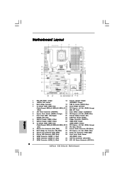
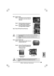
... FRONT Bottom: MIC IN LAN PHY AUDIO CODEC CD1 Super I/O FLOPPY1 HDMI_SPDIF1 1 Intel X58 CPU_FAN1 Chipset PWR_FAN1 PCIE1 CHA_FAN2 NB_FAN1 CHA_FAN1 RoHS PCI1 3-WaySLI PCIE2 PCI2 X58 Deluxe3 PCI Express 2.0 1394a 8Mb BIOS VIA VT6330 IDE1 PCIE3 PCI3 CMOS Battery Intel ICH10R PCIE4... SATAII_5_6 SATAII_3_4 SATAII_1_2 1 USB6_7 1 USB8_9 6 7 8 9 10 11 12 13 14 15 16 17 1 PS2_USB_PWR1 Jumper 18 Chassis Speaker Header 2 1366-Pin CPU Socket (SPEAKER 1, Purple) 3 North Bridge Controller 19 USB 2.0 Header (USB10, Blue) 4 3 x 240-pin DDR3 DIMM Slots 20 South Bridge Controller...
... FRONT Bottom: MIC IN LAN PHY AUDIO CODEC CD1 Super I/O FLOPPY1 HDMI_SPDIF1 1 Intel X58 CPU_FAN1 Chipset PWR_FAN1 PCIE1 CHA_FAN2 NB_FAN1 CHA_FAN1 RoHS PCI1 3-WaySLI PCIE2 PCI2 X58 Deluxe3 PCI Express 2.0 1394a 8Mb BIOS VIA VT6330 IDE1 PCIE3 PCI3 CMOS Battery Intel ICH10R PCIE4... SATAII_5_6 SATAII_3_4 SATAII_1_2 1 USB6_7 1 USB8_9 6 7 8 9 10 11 12 13 14 15 16 17 1 PS2_USB_PWR1 Jumper 18 Chassis Speaker Header 2 1366-Pin CPU Socket (SPEAKER 1, Purple) 3 North Bridge Controller 19 USB 2.0 Header (USB10, Blue) 4 3 x 240-pin DDR3 DIMM Slots 20 South Bridge Controller...
User Manual
Page 15
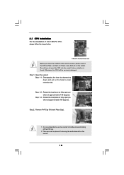
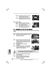
... retention tab. Step 1-3. This cap must be seriously damaged. Step 2. Remove PnP Cap (Pick and Place Cap). 1. Load Plate Contact Array Socket Body Load Lever 1366-Pin Socket Overview Before you insert the 1366-Pin CPU into the socket if above situation is found. Do not force to insert the CPU into the... socket, please check if the CPU surface is unclean or if there is recommended to use the cap tab to fully open position...
... retention tab. Step 1-3. This cap must be seriously damaged. Step 2. Remove PnP Cap (Pick and Place Cap). 1. Load Plate Contact Array Socket Body Load Lever 1366-Pin Socket Overview Before you insert the 1366-Pin CPU into the socket if above situation is found. Do not force to insert the CPU into the... socket, please check if the CPU surface is unclean or if there is recommended to use the cap tab to fully open position...

User Manual
Page 16
...4-2. Secure load lever with IHS (Integrated Heat Sink) up. Step 4. black line black line Step 3. Carefully place the CPU into the socket by the edges where are marked with the two alignment keys of the CPU with black lines. Rotate the load plate onto the IHS....Step 3-1. Step 3-3. Verify that the CPU is within the socket and properly mated to match the two orientation key notches of the socket. orientation key notch Pin1 Pin1 alignment key orientation key notch 1366-Pin CPU alignment key 1366-Pin Socket For proper inserting, please ensure to the orient keys. Step...
...4-2. Secure load lever with IHS (Integrated Heat Sink) up. Step 4. black line black line Step 3. Carefully place the CPU into the socket by the edges where are marked with the two alignment keys of the CPU with black lines. Rotate the load plate onto the IHS....Step 3-1. Step 3-3. Verify that the CPU is within the socket and properly mated to match the two orientation key notches of the socket. orientation key notch Pin1 Pin1 alignment key orientation key notch 1366-Pin CPU alignment key 1366-Pin Socket For proper inserting, please ensure to the orient keys. Step...

User Manual
Page 17
... to spray thermal interface material between the CPU and the heatsink to illustrate the installation of the heatsink for 1366-Pin CPU. Apply Thermal Interface Material Step 2. Place the heatsink onto the socket. Fan cables on side closest to the CPU_FAN connector (CPU_FAN1, see page 12, No. 35). Connect fan ... heatsink, you press down on fastener caps with thumb to the instruction manuals of your CPU fan and heatsink. Below is equipped with 1366-Pin socket that the CPU and the heatsink are oriented on side closest to dissipate heat. Step 4. Step 6. Repeat with Intel...
... to spray thermal interface material between the CPU and the heatsink to illustrate the installation of the heatsink for 1366-Pin CPU. Apply Thermal Interface Material Step 2. Place the heatsink onto the socket. Fan cables on side closest to the CPU_FAN connector (CPU_FAN1, see page 12, No. 35). Connect fan ... heatsink, you press down on fastener caps with thumb to the instruction manuals of your CPU fan and heatsink. Below is equipped with 1366-Pin socket that the CPU and the heatsink are oriented on side closest to dissipate heat. Step 4. Step 6. Repeat with Intel...
Quick Installation Guide
Page 2
Motherboard Layout English 1 PS2_USB_PWR1 Jumper 18 Chassis Speaker Header 2 1366-Pin CPU Socket (SPEAKER 1, Purple) 3 North Bridge Controller 19 USB 2.0 Header (USB10, Blue) 4 3 x 240-pin DDR3 DIMM Slots 20 South Bridge Controller (Triple ...HD_AUDIO1, Lime) 16 SATAII Connector (SATAII_3_4, Red) 35 CPU Fan Connector (CPU_FAN1) 17 SATAII Connector (SATAII_5_6, Red) 36 ATX 12V Power Connector (ATX12V1) 2 ASRock X58 Deluxe3 Motherboard White) 22 8Mb SPI Flash 5 ATX Power Connector (ATXPWR1) 23 Clear CMOS Jumper (CLRCMOS1) 6 System Panel Header (PANEL1, Orange) 24 PCI Express ...
Motherboard Layout English 1 PS2_USB_PWR1 Jumper 18 Chassis Speaker Header 2 1366-Pin CPU Socket (SPEAKER 1, Purple) 3 North Bridge Controller 19 USB 2.0 Header (USB10, Blue) 4 3 x 240-pin DDR3 DIMM Slots 20 South Bridge Controller (Triple ...HD_AUDIO1, Lime) 16 SATAII Connector (SATAII_3_4, Red) 35 CPU Fan Connector (CPU_FAN1) 17 SATAII Connector (SATAII_5_6, Red) 36 ATX 12V Power Connector (ATX12V1) 2 ASRock X58 Deluxe3 Motherboard White) 22 8Mb SPI Flash 5 ATX Power Connector (ATXPWR1) 23 Clear CMOS Jumper (CLRCMOS1) 6 System Panel Header (PANEL1, Orange) 24 PCI Express ...
Quick Installation Guide
Page 8
...Solid Capacitor design (100% Japan-made high-quality Conductive Polymer Capacitors) - System Bus up to -Use USB 2.0 Ports ASRock X58 Deluxe3 Motherboard English Southbridge: Intel® ICH10R - Supports DDR3 2000(OC)/1866(OC)/1600(OC)/1333(OC)/ 1066 non-ECC... @ x8 / N/A mode) (Double-wide slot spacing between each PCI-E slot) - 3 x PCI slots - Premium Blu-ray audio support - Intel® Socket 1366 CoreTM i7 Processor Extreme Edition / CoreTM i7 Processor Supports Intel® Dynamic Speed Technology - capacity of system memory: 24GB (see CAUTION 2) - Supports NVIDIA®...
...Solid Capacitor design (100% Japan-made high-quality Conductive Polymer Capacitors) - System Bus up to -Use USB 2.0 Ports ASRock X58 Deluxe3 Motherboard English Southbridge: Intel® ICH10R - Supports DDR3 2000(OC)/1866(OC)/1600(OC)/1333(OC)/ 1066 non-ECC... @ x8 / N/A mode) (Double-wide slot spacing between each PCI-E slot) - 3 x PCI slots - Premium Blu-ray audio support - Intel® Socket 1366 CoreTM i7 Processor Extreme Edition / CoreTM i7 Processor Supports Intel® Dynamic Speed Technology - capacity of system memory: 24GB (see CAUTION 2) - Supports NVIDIA®...

Quick Installation Guide
Page 14
... the chassis, please do not over-tighten the screws! Installation Pre-installation Precautions Take note of Intel 1366-Pin CPU, please follow the steps below. 1366-Pin Socket Overview Before you install motherboard components or change any bent pin on the carpet or the like. Hold... motherboard, peripherals, and/or components. 2. Unplug the power cord from the wall socket before you insert the 1366-Pin CPU into the socket, please check if the CPU surface is unclean or if there is found. Otherwise, the CPU will be seriously damaged. 14 ASRock X58 Deluxe3 Motherboard English
... the chassis, please do not over-tighten the screws! Installation Pre-installation Precautions Take note of Intel 1366-Pin CPU, please follow the steps below. 1366-Pin Socket Overview Before you install motherboard components or change any bent pin on the carpet or the like. Hold... motherboard, peripherals, and/or components. 2. Unplug the power cord from the wall socket before you insert the 1366-Pin CPU into the socket, please check if the CPU surface is unclean or if there is found. Otherwise, the CPU will be seriously damaged. 14 ASRock X58 Deluxe3 Motherboard English
Quick Installation Guide
Page 15
.... Rotate the load plate to match the two orientation key notches of the socket. 15 ASRock X58 Deluxe3 Motherboard English Remove PnP Cap (Pick and Place Cap). It is recommended to use the cap tab to clear retention tab. Step 3. Insert the 1366-Pin CPU: Step 3-1. Locate Pin1 and the two orientation key notches. orientation...
.... Rotate the load plate to match the two orientation key notches of the socket. 15 ASRock X58 Deluxe3 Motherboard English Remove PnP Cap (Pick and Place Cap). It is recommended to use the cap tab to clear retention tab. Step 3. Insert the 1366-Pin CPU: Step 3-1. Locate Pin1 and the two orientation key notches. orientation...
Quick Installation Guide
Page 16
...oriented on side closest to install and lock. Step 3-4. Close the socket: Step 4-1. Step 4-3. Apply thermal interface material onto center of the heatsink for 1366-Pin CPU. Place the heatsink onto the socket. Rotate the fastener clockwise, then press down on load plate, ...the socket and properly mated to illustrate the installation of IHS on the motherboard (CPU_FAN1, see page 2, No. 35). English Step 2. Align fasteners with the CPU fan connector on the motherboard. Step 5. Step 6. 16 Connect fan header with the motherboard throughholes. ASRock X58 Deluxe3 Motherboard...
...oriented on side closest to install and lock. Step 3-4. Close the socket: Step 4-1. Step 4-3. Apply thermal interface material onto center of the heatsink for 1366-Pin CPU. Place the heatsink onto the socket. Rotate the fastener clockwise, then press down on load plate, ...the socket and properly mated to illustrate the installation of IHS on the motherboard (CPU_FAN1, see page 2, No. 35). English Step 2. Align fasteners with the CPU fan connector on the motherboard. Step 5. Step 6. 16 Connect fan header with the motherboard throughholes. ASRock X58 Deluxe3 Motherboard...