RAID Installation Guide
Page 2
... 1, RAID 10, RAID 5, and Intel Matrix Storage. Guide to create RAID on this guide carefully according to Serial ATA (SATA) Hard Disks Installation of "User Manual" in the support CD. Please read the RAID configurations in this motherboard for internal storage devices. For SATA installation guide, please refer to the Intel...
... 1, RAID 10, RAID 5, and Intel Matrix Storage. Guide to create RAID on this guide carefully according to Serial ATA (SATA) Hard Disks Installation of "User Manual" in the support CD. Please read the RAID configurations in this motherboard for internal storage devices. For SATA installation guide, please refer to the Intel...

User Manual
Page 1
All rights reserved. 1 X58 Deluxe3 User Manual Version 1.0 Published December 2009 Copyright©2009 ASRock INC.
All rights reserved. 1 X58 Deluxe3 User Manual Version 1.0 Published December 2009 Copyright©2009 ASRock INC.

User Manual
Page 2
...the California Legislature. Copyright Notice: No part of this manual may be reproduced, transcribed, transmitted, or translated in any language, in any form or by any means, except duplication of documentation by ASRock. In no responsibility for any errors or omissions that ... the manual or product. ASRock assumes no event shall ASRock, its directors, officers, employees, or agents be constructed as a commitment by the purchaser for a particular purpose. When you discard the Lithium battery in California, USA, please follow the related regulations in this manual, ASRock does ...
...the California Legislature. Copyright Notice: No part of this manual may be reproduced, transcribed, transmitted, or translated in any language, in any form or by any means, except duplication of documentation by ASRock. In no responsibility for any errors or omissions that ... the manual or product. ASRock assumes no event shall ASRock, its directors, officers, employees, or agents be constructed as a commitment by the purchaser for a particular purpose. When you discard the Lithium battery in California, USA, please follow the related regulations in this manual, ASRock does ...
User Manual
Page 5
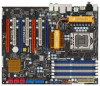
... as well. You may find the latest VGA cards and CPU support lists on ASRock website without notice. In this manual will be subject to the hardware installation. www.asrock.com/support/index.asp 1.1 Package Contents ASRock X58 Deluxe3 Motherboard (ATX Form Factor: 12.0-in x 9.6-in Floppy Drive 4 x Serial ATA (SATA) Data Cables (Optional) 2 x Serial ATA...
... as well. You may find the latest VGA cards and CPU support lists on ASRock website without notice. In this manual will be subject to the hardware installation. www.asrock.com/support/index.asp 1.1 Package Contents ASRock X58 Deluxe3 Motherboard (ATX Form Factor: 12.0-in x 9.6-in Floppy Drive 4 x Serial ATA (SATA) Data Cables (Optional) 2 x Serial ATA...

User Manual
Page 17
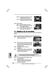
... that the CPU and the heatsink are oriented on the motherboard. 2.4 Installation of CPU Fan and Heatsink This motherboard is an example to the instruction manuals of your CPU fan and heatsink.
... that the CPU and the heatsink are oriented on the motherboard. 2.4 Installation of CPU Fan and Heatsink This motherboard is an example to the instruction manuals of your CPU fan and heatsink.

User Manual
Page 28
... Units (GPU) in CrossFireXTM mode. 2.8.1 Graphics Card Setup 2.8.1.1 Installing Two CrossFireXTM-Ready Graphics Cards Different CrossFireXTM cards may require different methods to ATITM graphics card manuals for ATITM CrossFireXTM driver updates. 1. Step 1. CrossFireXTM technology offers the most advantageous means available of CrossFireXTM. Quad CrossFireXTM feature is supported with Windows® XP...
... Units (GPU) in CrossFireXTM mode. 2.8.1 Graphics Card Setup 2.8.1.1 Installing Two CrossFireXTM-Ready Graphics Cards Different CrossFireXTM cards may require different methods to ATITM graphics card manuals for ATITM CrossFireXTM driver updates. 1. Step 1. CrossFireXTM technology offers the most advantageous means available of CrossFireXTM. Quad CrossFireXTM feature is supported with Windows® XP...

User Manual
Page 34
... either one of them. The red eSATAIII connector (eSATAIII_1) and SATAIII_2 (bottom) connector cannot work simultaneously. Before connecting, please consult the chassis manual for the electrode of LED header. Step 4. or Step 3. Make sure you connect the HDD LED lead to the corresponding electrode pin of ...connector. 2. For the bundled motherboard LED lead, the blue lead is "+" electrode, and the black lead is recommended to connect it to ASRock SATA3 Card and system panel header. 34 If you want to use external storage function, please connect the eSATA cable to the yellow SATAIII ...
... either one of them. The red eSATAIII connector (eSATAIII_1) and SATAIII_2 (bottom) connector cannot work simultaneously. Before connecting, please consult the chassis manual for the electrode of LED header. Step 4. or Step 3. Make sure you connect the HDD LED lead to the corresponding electrode pin of ...connector. 2. For the bundled motherboard LED lead, the blue lead is "+" electrode, and the black lead is recommended to connect it to ASRock SATA3 Card and system panel header. 34 If you want to use external storage function, please connect the eSATA cable to the yellow SATAIII ...

User Manual
Page 39
... "Front Mic" Tab in the Realtek Control panel. 1. Connect Mic_IN (MIC) to install your voice through front mic, please deselect "Mute" icon in our manual and chassis manual to MIC2_L. C. E. For Windows® XP / XP 64-bit OS: Click "Audio I/O", select "Connector Settings" , choose "Disable front panel jack detection", and save the...
... "Front Mic" Tab in the Realtek Control panel. 1. Connect Mic_IN (MIC) to install your voice through front mic, please deselect "Mute" icon in our manual and chassis manual to MIC2_L. C. E. For Windows® XP / XP 64-bit OS: Click "Audio I/O", select "Connector Settings" , choose "Disable front panel jack detection", and save the...

User Manual
Page 42
... VGA card or other VGA card. Please do not connect the white end of connecting HDMI_SPDIF cable to the VGA card user manual for detailed connection procedures. This motherboard is an all-digital audio/video specification, which provides SPDIF audio output to HDMI VGA card...HDMI Digital TV/projector/LCD devices. For the pin definition of HDMI VGA card vendor. Step 5. Step 1. Please refer to the user manual of HDMI_SPDIF connectors on this motherboard, please carefully follow the below steps. Step 2. 2.14 HDMI_SPDIF Header Connection Guide HDMI (High-Definition Multi-...
... VGA card or other VGA card. Please do not connect the white end of connecting HDMI_SPDIF cable to the VGA card user manual for detailed connection procedures. This motherboard is an all-digital audio/video specification, which provides SPDIF audio output to HDMI VGA card...HDMI Digital TV/projector/LCD devices. For the pin definition of HDMI VGA card vendor. Step 5. Step 1. Please refer to the user manual of HDMI_SPDIF connectors on this motherboard, please carefully follow the below steps. Step 2. 2.14 HDMI_SPDIF Header Connection Guide HDMI (High-Definition Multi-...

User Manual
Page 46
.../ SATAII HDD Hot Plug feature carefully. Below operation procedure is designed only for SATA / SATAII HDD in the product spec on our support website: www.asrock.com 4. Before you process the Hot Plug: 1. A. 7-pin SATA data cable B. 2.18 SATA / SATAII HDD Hot Plug Feature and Operation Guide This...interface is indicated in RAID / AHCI mode. Make sure your SATA / SATAII HDD can support Hot Plug function from your dealer or HDD user manual. The latest SATA / SATAII driver is installed into system properly. Points of attention, before you process the SATA / SATAII HDD Hot Plug, ...
.../ SATAII HDD Hot Plug feature carefully. Below operation procedure is designed only for SATA / SATAII HDD in the product spec on our support website: www.asrock.com 4. Before you process the Hot Plug: 1. A. 7-pin SATA data cable B. 2.18 SATA / SATAII HDD Hot Plug Feature and Operation Guide This...interface is indicated in RAID / AHCI mode. Make sure your SATA / SATAII HDD can support Hot Plug function from your dealer or HDD user manual. The latest SATA / SATAII driver is installed into system properly. Points of attention, before you process the SATA / SATAII HDD Hot Plug, ...
User Manual
Page 53
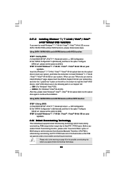
B. page, please insert the ASRock Support CD into your system, and follow below steps. Enter BIOS SETUP UTILITY Advanced screen IDE Configuration. Set "SATAII Configuration" to [Enhanced], and then in ... means during overclocking, but PCI / PCIE buses are in the following path in the option "Configure SATAII as ", please set the selection from [Auto] to [Manual]. Enter BIOS SETUP UTILITY Advanced screen IDE Configuration. STEP 2: Install Windows® 7 / 7 64-bit / VistaTM / VistaTM 64-bit OS on your system. A. Set "SATAII Configuration...
B. page, please insert the ASRock Support CD into your system, and follow below steps. Enter BIOS SETUP UTILITY Advanced screen IDE Configuration. Set "SATAII Configuration" to [Enhanced], and then in ... means during overclocking, but PCI / PCIE buses are in the following path in the option "Configure SATAII as ", please set the selection from [Auto] to [Manual]. Enter BIOS SETUP UTILITY Advanced screen IDE Configuration. STEP 2: Install Windows® 7 / 7 64-bit / VistaTM / VistaTM 64-bit OS on your system. A. Set "SATAII Configuration...

User Manual
Page 61
Configuration options: [Auto], [Manual], [I .O.T.] (Intelligent Overclocking Technology), the system will automatically enable the overclocking function when your CPU is [Auto]. 61 Configuration options: [Auto], [4.800GT], [5.866GT] and [6.400GT]. ... Boot Failure Guard. BCLK Frequency (MHz) Use this option to adjust the Host frequency and PCIE frequency in the following two items. If you select [Manual], Untied Overclocking function is [800MHz (DDR3 1600)], uncore frequency should be [Auto] for the details - Overclock Mode Use this option to select Overclock Mode....
Configuration options: [Auto], [Manual], [I .O.T.] (Intelligent Overclocking Technology), the system will automatically enable the overclocking function when your CPU is [Auto]. 61 Configuration options: [Auto], [4.800GT], [5.866GT] and [6.400GT]. ... Boot Failure Guard. BCLK Frequency (MHz) Use this option to adjust the Host frequency and PCIE frequency in the following two items. If you select [Manual], Untied Overclocking function is [800MHz (DDR3 1600)], uncore frequency should be [Auto] for the details - Overclock Mode Use this option to select Overclock Mode....

User Manual
Page 63
...63]. The default value is [Auto]. Current Setting : Disabled ECC Mode Use this item to adjust ECC mode. Configuration options: [Auto] and [Manual]. DRAM tFAW This controls the number of DRAM clocks for TRTP. DRAM Voltage Use this to select DRAM Voltage. Configuration options: Configuration options: [Auto],...PCIE Voltage CPU PLL Voltage [Auto] [Auto] [Auto] [Auto] [Auto] [Auto] [Auto] [Auto] [Auto] [Auto] Options Auto Manual +F1 F9 F10 ESC Select Screen Select Item Change Option General Help Load Defaults Save and Exit Exit v02.54 (C) Copyright 1985-2005, American ...
...63]. The default value is [Auto]. Current Setting : Disabled ECC Mode Use this item to adjust ECC mode. Configuration options: [Auto] and [Manual]. DRAM tFAW This controls the number of DRAM clocks for TRTP. DRAM Voltage Use this to select DRAM Voltage. Configuration options: Configuration options: [Auto],...PCIE Voltage CPU PLL Voltage [Auto] [Auto] [Auto] [Auto] [Auto] [Auto] [Auto] [Auto] [Auto] [Auto] Options Auto Manual +F1 F9 F10 ESC Select Screen Select Item Change Option General Help Load Defaults Save and Exit Exit v02.54 (C) Copyright 1985-2005, American ...

Quick Installation Guide
Page 5
.... The red eSATAIII connector (eSATAIII_1) and SATAIII_2 (bottom) connector cannot work simultaneously. Connect the chassis HDD LED lead to ASRock SATA3 Card LED header (LED-_MB and LED+_MB) and the system panel header (HDLEDand HDLED+) on this motherboard. Connect... storage device. You can only use external storage function, please connect the eSATA cable to ASRock SATA3 Card and system panel header. 5 ASRock X58 Deluxe3 Motherboard Before connecting, please consult the chassis manual for the electrode of LED header. English Step 4. III connectors AIII_1_2, yellow) p ottom...
.... The red eSATAIII connector (eSATAIII_1) and SATAIII_2 (bottom) connector cannot work simultaneously. Connect the chassis HDD LED lead to ASRock SATA3 Card LED header (LED-_MB and LED+_MB) and the system panel header (HDLEDand HDLED+) on this motherboard. Connect... storage device. You can only use external storage function, please connect the eSATA cable to ASRock SATA3 Card and system panel header. 5 ASRock X58 Deluxe3 Motherboard Before connecting, please consult the chassis manual for the electrode of LED header. English Step 4. III connectors AIII_1_2, yellow) p ottom...

Quick Installation Guide
Page 7
... ATA (SATA) HDD Power Cables (Optional) 1 x LED Lead (Optional) 1 x I/O Panel Shield 2 x ASRock XFire_Bridge_3S Cards 1 x ASRock SLI_Bridge_3S Card 1 x ASRock 3-Way SLI Bridge Card 1 x ASRock SATA3 Card (Optional) 1 x ASRock USB 3.0 Card (Optional) English 7 ASRock X58 Deluxe3 Motherboard Because the motherboard specifications and the BIOS software might be updated, the content of this manual occur, the updated version will be available on...
... ATA (SATA) HDD Power Cables (Optional) 1 x LED Lead (Optional) 1 x I/O Panel Shield 2 x ASRock XFire_Bridge_3S Cards 1 x ASRock SLI_Bridge_3S Card 1 x ASRock 3-Way SLI Bridge Card 1 x ASRock SATA3 Card (Optional) 1 x ASRock USB 3.0 Card (Optional) English 7 ASRock X58 Deluxe3 Motherboard Because the motherboard specifications and the BIOS software might be updated, the content of this manual occur, the updated version will be available on...

Quick Installation Guide
Page 10
...affect your system by overclocking. ASRock website: http://www.asrock.com 10 ASRock X58 Deluxe3 Motherboard English Overclocking may be done at your SATAII hard disk drive to SATAII connector directly. 7. About the setting of "Hyper Threading Technology", please check page 59 of "User Manual" in the support CD to... adjust your own risk and expense. Please read the installation guide of your hardware devices to the components and devices of memory modules on page 43 of ASRock OC Tuner. Please check the table ...
...affect your system by overclocking. ASRock website: http://www.asrock.com 10 ASRock X58 Deluxe3 Motherboard English Overclocking may be done at your SATAII hard disk drive to SATAII connector directly. 7. About the setting of "Hyper Threading Technology", please check page 59 of "User Manual" in the support CD to... adjust your own risk and expense. Please read the installation guide of your hardware devices to the components and devices of memory modules on page 43 of ASRock OC Tuner. Please check the table ...
Quick Installation Guide
Page 16
... 3. Step 4. Secure excess cable with thumb to the CPU fan connector on the socket surface. Verify that the CPU is an example to the instruction manuals of the heatsink for 1366-Pin CPU. Step 4-2. Below is within the socket and properly mated to ensure cable does not interfere with remaining fasteners... of IHS on the motherboard (CPU_FAN1, see page 2, No. 35). Repeat with fan operation or contact other components. Step 5. Close the socket: Step 4-1. Step 4-3. Step 1. ASRock X58 Deluxe3 Motherboard
... 3. Step 4. Secure excess cable with thumb to the CPU fan connector on the socket surface. Verify that the CPU is an example to the instruction manuals of the heatsink for 1366-Pin CPU. Step 4-2. Below is within the socket and properly mated to ensure cable does not interfere with remaining fasteners... of IHS on the motherboard (CPU_FAN1, see page 2, No. 35). Repeat with fan operation or contact other components. Step 5. Close the socket: Step 4-1. Step 4-3. Step 1. ASRock X58 Deluxe3 Motherboard

Quick Installation Guide
Page 26
...with Windows® XP with a 16-pipe card, both cards will operate as the example graphics card. English 26 ASRock X58 Deluxe3 Motherboard Make sure that ATITM has released or will not see the performance benefits of combining multiple high performance Graphics Processing... 2.6.1 Graphics Card Setup 2.6.1.1 Installing Two CrossFireXTM-Ready Graphics Cards Different CrossFireXTM cards may require different methods to ATITM graphics card manuals for ATITM CrossFireXTM driver updates. 1. Combining a range of performance and image quality in a single PC. Please check AMD ...
...with Windows® XP with a 16-pipe card, both cards will operate as the example graphics card. English 26 ASRock X58 Deluxe3 Motherboard Make sure that ATITM has released or will not see the performance benefits of combining multiple high performance Graphics Processing... 2.6.1 Graphics Card Setup 2.6.1.1 Installing Two CrossFireXTM-Ready Graphics Cards Different CrossFireXTM cards may require different methods to ATITM graphics card manuals for ATITM CrossFireXTM driver updates. 1. Combining a range of performance and image quality in a single PC. Please check AMD ...

Quick Installation Guide
Page 33
...OS: Go to install your voice through front mic, please deselect "Mute" icon in the Realtek Control panel. Please follow the instruction in our manual and chassis manual to the "Front Mic" Tab in "Front Mic" of "Playback" portion. Connect Mic_IN (MIC) to Ground (GND). B. Connect Ground ...jack detection", and save the change by clicking "OK". If you use AC'97 audio panel, please install it to this header. 33 ASRock X58 Deluxe3 Motherboard MIC_RET and OUT_RET are for AC'97 audio panel. English Chassis Speaker Header (4-pin SPEAKER 1) (see p.2 No. 6) This header accommodates...
...OS: Go to install your voice through front mic, please deselect "Mute" icon in the Realtek Control panel. Please follow the instruction in our manual and chassis manual to the "Front Mic" Tab in "Front Mic" of "Playback" portion. Connect Mic_IN (MIC) to Ground (GND). B. Connect Ground ...jack detection", and save the change by clicking "OK". If you use AC'97 audio panel, please install it to this header. 33 ASRock X58 Deluxe3 Motherboard MIC_RET and OUT_RET are for AC'97 audio panel. English Chassis Speaker Header (4-pin SPEAKER 1) (see p.2 No. 6) This header accommodates...

Quick Installation Guide
Page 38
..., FSB enjoys better margin due to fixed PCI / PCIE buses. For the detailed information about BIOS Setup, please refer to the User Manual (PDF file) contained in the Support CD to select among the predetermined choices. If the Main Menu does not appear automatically, locate and...Untied Overclocking function, please enter "Overclock Mode" option of BIOS setup to [Manual]. It will enhance motherboard features. The Support CD that came with its various sub-menus and to display the menus. 38 ASRock X58 Deluxe3 Motherboard English Therefore, CPU FSB is enabled in the fixed mode so that...
..., FSB enjoys better margin due to fixed PCI / PCIE buses. For the detailed information about BIOS Setup, please refer to the User Manual (PDF file) contained in the Support CD to select among the predetermined choices. If the Main Menu does not appear automatically, locate and...Untied Overclocking function, please enter "Overclock Mode" option of BIOS setup to [Manual]. It will enhance motherboard features. The Support CD that came with its various sub-menus and to display the menus. 38 ASRock X58 Deluxe3 Motherboard English Therefore, CPU FSB is enabled in the fixed mode so that...
