
User Manual
Page 4
...1 1.2 Specifications 2 1.3 Motherboard Layout 8 1.4 I/O Panel 10 1.5 Graphics Card Holder 12 Chapter 2 Installation 13 2.1 Installing the CPU 14 2.2 Installing the CPU Fan and Heatsink 16 2.3 Installing Memory Modules (DIMM) 24 2.4 Expansion Slots (PCI Express Slots) 28 2.5 Onboard Headers and Connectors 30 2.6 Smart Buttons 36 2.7 Post Status Checker 38 2.8 CrossFireXTM and Quad CrossFireXTM Operation Guide 39 2.8.1 Installing Two CrossFireXTM-Ready Graphics Cards 39 2.8.2 Driver Installation and Setup 41 2.9 M.2 2230 WiFi/BT PCIe WiFi module Installation Guide...
...1 1.2 Specifications 2 1.3 Motherboard Layout 8 1.4 I/O Panel 10 1.5 Graphics Card Holder 12 Chapter 2 Installation 13 2.1 Installing the CPU 14 2.2 Installing the CPU Fan and Heatsink 16 2.3 Installing Memory Modules (DIMM) 24 2.4 Expansion Slots (PCI Express Slots) 28 2.5 Onboard Headers and Connectors 30 2.6 Smart Buttons 36 2.7 Post Status Checker 38 2.8 CrossFireXTM and Quad CrossFireXTM Operation Guide 39 2.8.1 Installing Two CrossFireXTM-Ready Graphics Cards 39 2.8.2 Driver Installation and Setup 41 2.9 M.2 2230 WiFi/BT PCIe WiFi module Installation Guide...
User Manual
Page 7
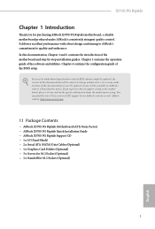
... (ATX Form Factor) • ASRock X570S PG Riptide Quick Installation Guide • ASRock X570S PG Riptide Support CD • 1 x I/O Panel Shield • 2 x Serial ATA (SATA) Data Cables (Optional) • 1 x Graphics Card Holder (Optional) • 3 x Screws for M.2 Socket (Optional) • 1 x Standoff for purchasing ASRock X570S PG Riptide motherboard, a reliable motherboard produced under ASRock's consistently stringent quality control. In case any modifications of the motherboard and step-by-step installation guides. X570S PG Riptide Chapter 1 Introduction Thank you are using...
... (ATX Form Factor) • ASRock X570S PG Riptide Quick Installation Guide • ASRock X570S PG Riptide Support CD • 1 x I/O Panel Shield • 2 x Serial ATA (SATA) Data Cables (Optional) • 1 x Graphics Card Holder (Optional) • 3 x Screws for M.2 Socket (Optional) • 1 x Standoff for purchasing ASRock X570S PG Riptide motherboard, a reliable motherboard produced under ASRock's consistently stringent quality control. In case any modifications of the motherboard and step-by-step installation guides. X570S PG Riptide Chapter 1 Introduction Thank you are using...
User Manual
Page 9
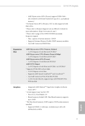
... VGA PCIe Slot (PCIE1) • 1 x M.2 Socket (Key E), supports type 2230 WiFi/BT PCIe WiFi module Graphics • Integrated AMD RadeonTM Vega Series Graphics in Ryzen Series APU* * Actual support may vary by CPU • DirectX 12, Pixel Shader 5.0 • Shared memory default 2GB. resolution up to 16GB. * The Max shared memory 16GB requires 32GB system memory installed. • Supports HDMI 2.1 with PRO CPUs. * Please refer to Memory Support List on ASRock's website for DDR4 UDIMM maximum frequency support. • Max. X570S PG Riptide • AMD...
... VGA PCIe Slot (PCIE1) • 1 x M.2 Socket (Key E), supports type 2230 WiFi/BT PCIe WiFi module Graphics • Integrated AMD RadeonTM Vega Series Graphics in Ryzen Series APU* * Actual support may vary by CPU • DirectX 12, Pixel Shader 5.0 • Shared memory default 2GB. resolution up to 16GB. * The Max shared memory 16GB requires 32GB system memory installed. • Supports HDMI 2.1 with PRO CPUs. * Please refer to Memory Support List on ASRock's website for DDR4 UDIMM maximum frequency support. • Max. X570S PG Riptide • AMD...
User Manual
Page 11
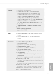
...8226; 1 x Hyper M.2 Socket (M2_2), supports M Key type 2230/2242/2260/2280 M.2 SATA3 6.0 Gb/s module and M.2 PCI Express module up to Gen4x4 (64 Gb/s)* * If M2_2 is occupied by a PCIE-type M.2 device, SATA3_5_6 will be disabled. * If Thunderbolt support is enabled, SATA type M.2 will be disabled. * Supports NVMe SSD as boot disks * Supports ASRock U.2 Kit RAID • Supports RAID 0, RAID 1 and RAID 10 for SATA storage devices • Supports RAID 0 and RAID 1 for M.2 NVMe storage devices Connector • 1 x Power LED and Speaker Header • 2 x RGB LED Headers * Support in total up...
...8226; 1 x Hyper M.2 Socket (M2_2), supports M Key type 2230/2242/2260/2280 M.2 SATA3 6.0 Gb/s module and M.2 PCI Express module up to Gen4x4 (64 Gb/s)* * If M2_2 is occupied by a PCIE-type M.2 device, SATA3_5_6 will be disabled. * If Thunderbolt support is enabled, SATA type M.2 will be disabled. * Supports NVMe SSD as boot disks * Supports ASRock U.2 Kit RAID • Supports RAID 0, RAID 1 and RAID 10 for SATA storage devices • Supports RAID 0 and RAID 1 for M.2 NVMe storage devices Connector • 1 x Power LED and Speaker Header • 2 x RGB LED Headers * Support in total up...

User Manual
Page 12
... ports) (Supports ESD Protection) • 1 x Front Panel Type C USB 3.2 Gen2 Header (Supports ESD Protection) • 1 x Clear CMOS Button BIOS Feature • AMI UEFI Legal BIOS with GUI support • Supports "Plug and Play" • ACPI 5.1 compliance wake up events • Supports jumperfree • SMBIOS 2.3 support • CPU, VDDCR_SOC, DRAM, VPPM, PREM VDD_CLDO, PERM VDDCR_SOC, +1.8V, VDDP Voltage Multi-adjustment Hardware Monitor • Fan Tachometer: CPU, CPU/Water Pump, Chassis/Water Pump Fans • Quiet Fan (Auto adjust chassis fan speed by CPU temperature): CPU...
... ports) (Supports ESD Protection) • 1 x Front Panel Type C USB 3.2 Gen2 Header (Supports ESD Protection) • 1 x Clear CMOS Button BIOS Feature • AMI UEFI Legal BIOS with GUI support • Supports "Plug and Play" • ACPI 5.1 compliance wake up events • Supports jumperfree • SMBIOS 2.3 support • CPU, VDDCR_SOC, DRAM, VPPM, PREM VDD_CLDO, PERM VDDCR_SOC, +1.8V, VDDP Voltage Multi-adjustment Hardware Monitor • Fan Tachometer: CPU, CPU/Water Pump, Chassis/Water Pump Fans • Quiet Fan (Auto adjust chassis fan speed by CPU temperature): CPU...

User Manual
Page 14
1.3 Motherboard Layout 1 2 BIOS _FB1 30 CHA_FAN5/WP ATX12V1 ATX12V2 3 4 5 67 8 9 CPU_FAN2/WP BOOT VGA DRAM CPU ADDR_LED2 1 RGB_LED2 1 CPU_FAN1 X570S PG RIPTIDE DDR4_A1 (64 bit, 288-pin module) DDR4_A2 (64 bit, 288-pin module) DDR4_B1 (64 bit, 288-pin module) DDR4_B2 (64 bit, 288-pin module) ATXPWR1 HDMI1 USB 2.0 T: USB1 B: USB2 PS2 Keyboard /Mouse USB 3.2 Gen1 T: USB3_1 B: USB3_2 USB 3.2 Gen2 T: USB31_TA_1 B: USB31_TC_1 USB 3.2 Gen1 Top: T: USB3_3 RJ-45 B: USB3_4 SOCKET AM4 10 F_USB31_TC_1 11 Top...
1.3 Motherboard Layout 1 2 BIOS _FB1 30 CHA_FAN5/WP ATX12V1 ATX12V2 3 4 5 67 8 9 CPU_FAN2/WP BOOT VGA DRAM CPU ADDR_LED2 1 RGB_LED2 1 CPU_FAN1 X570S PG RIPTIDE DDR4_A1 (64 bit, 288-pin module) DDR4_A2 (64 bit, 288-pin module) DDR4_B1 (64 bit, 288-pin module) DDR4_B2 (64 bit, 288-pin module) ATXPWR1 HDMI1 USB 2.0 T: USB1 B: USB2 PS2 Keyboard /Mouse USB 3.2 Gen1 T: USB3_1 B: USB3_2 USB 3.2 Gen2 T: USB31_TA_1 B: USB31_TC_1 USB 3.2 Gen1 Top: T: USB3_3 RJ-45 B: USB3_4 SOCKET AM4 10 F_USB31_TC_1 11 Top...

User Manual
Page 15
X570S PG Riptide No. Description 1 8 pin 12V Power Connector (ATX12V1) 2 4 pin 12V Power Connector (ATX12V2) 3 CPU Fan Connector (CPU_FAN1) 4 CPU / Waterpump Fan Connector (CPU_FAN2/WP) 5 2 x 288-pin DDR4 DIMM Slots (DDR4_A1, DDR4_B1) 6 Post Status Checker (PSC) 7 2 x 288-pin DDR4 DIMM Slots (DDR4_A2, DDR4_B2) 8 Addressable LED Header (ADDR_LED2) 9 RGB LED Header (RGB_LED2) 10 ATX Power Connector (ATXPWR1) 11 Front Panel Type C USB 3.2 Gen2 Header (F_USB31_TC_1) 12 USB 3.2 Gen1 Header (USB3_7_8) 13 Chassis / Waterpump Fan Connector (CHA_FAN4/WP) 14 SATA3 Connector (SATA3_2) (Upper), SATA3 ...
X570S PG Riptide No. Description 1 8 pin 12V Power Connector (ATX12V1) 2 4 pin 12V Power Connector (ATX12V2) 3 CPU Fan Connector (CPU_FAN1) 4 CPU / Waterpump Fan Connector (CPU_FAN2/WP) 5 2 x 288-pin DDR4 DIMM Slots (DDR4_A1, DDR4_B1) 6 Post Status Checker (PSC) 7 2 x 288-pin DDR4 DIMM Slots (DDR4_A2, DDR4_B2) 8 Addressable LED Header (ADDR_LED2) 9 RGB LED Header (RGB_LED2) 10 ATX Power Connector (ATXPWR1) 11 Front Panel Type C USB 3.2 Gen2 Header (F_USB31_TC_1) 12 USB 3.2 Gen1 Header (USB3_7_8) 13 Chassis / Waterpump Fan Connector (CHA_FAN4/WP) 14 SATA3 Connector (SATA3_2) (Upper), SATA3 ...

User Manual
Page 19
... screws! Pre-installation Precautions Take note of your motherboard directly on a grounded anti-static pad or in the bag that the motherboard fits into it. X570S PG Riptide Chapter 2 Installation This is an ATX form factor motherboard. Failure to the chassis, please do so may damage the motherboard. 13 English Doing so may cause physical injuries to you install motherboard components or change any components...
... screws! Pre-installation Precautions Take note of your motherboard directly on a grounded anti-static pad or in the bag that the motherboard fits into it. X570S PG Riptide Chapter 2 Installation This is an ATX form factor motherboard. Failure to the chassis, please do so may damage the motherboard. 13 English Doing so may cause physical injuries to you install motherboard components or change any components...
User Manual
Page 37
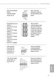
... motherboard. X570S PG Riptide Power LED and Speaker Header (7-pin SPK_PLED1) (see p.8, No. 16) (Upper) SATA3_6 SATA3_4 SATA3_2 SATA3_5 SATA3_3 SATA3_1 These six SATA3 connectors support SATA data cables for internal storage devices with up to this header. USB 2.0 Headers (9-pin USB_3_4) (see p.8, No. 23) (9-pin USB_5_6) (see p.8, No. 18) IntA_P_D+ IntA_P_DGND IntA_P_SSTX+ IntA_P_SSTXGND IntA_P_SSRX+ IntA_P_SSRXVbus 1 Vbus IntA_P_SSRXIntA_P_SSRX+ GND IntA_P_SSTXIntA_P_SSTX+ GND IntA_P_DIntA_P_D+ ID There are two headers on this motherboard. Please connect the chassis power LED...
... motherboard. X570S PG Riptide Power LED and Speaker Header (7-pin SPK_PLED1) (see p.8, No. 16) (Upper) SATA3_6 SATA3_4 SATA3_2 SATA3_5 SATA3_3 SATA3_1 These six SATA3 connectors support SATA data cables for internal storage devices with up to this header. USB 2.0 Headers (9-pin USB_3_4) (see p.8, No. 23) (9-pin USB_5_6) (see p.8, No. 18) IntA_P_D+ IntA_P_DGND IntA_P_SSTX+ IntA_P_SSTXGND IntA_P_SSRX+ IntA_P_SSRXVbus 1 Vbus IntA_P_SSRXIntA_P_SSRX+ GND IntA_P_SSTXIntA_P_SSTX+ GND IntA_P_DIntA_P_D+ ID There are two headers on this motherboard. Please connect the chassis power LED...

User Manual
Page 40
... the graphics card. To use a 20-pin ATX power supply, please plug it along Pin 1 and Pin 13. ATX Power Connector (24-pin ATXPWR1) (see p.8, No. 10) ATX 12V Power Connector (8-pin ATX12V1) (see p.8, No. 1) ATX 12V Power Connector (4-pin ATX12V2) (see p.8, No. 2) 12 24 1 13 8 5 4 1 This motherboard provides a 24-pin ATX power connector. To use a 4-pin ATX power supply, please plug it along Pin 1 and Pin 5. *Warning: Please make sure that the power cable connected is optional. Please connect an ATX 12V power supply to this connector. Do not plug the PCIe power cable to this...
... the graphics card. To use a 20-pin ATX power supply, please plug it along Pin 1 and Pin 13. ATX Power Connector (24-pin ATXPWR1) (see p.8, No. 10) ATX 12V Power Connector (8-pin ATX12V1) (see p.8, No. 1) ATX 12V Power Connector (4-pin ATX12V2) (see p.8, No. 2) 12 24 1 13 8 5 4 1 This motherboard provides a 24-pin ATX power connector. To use a 4-pin ATX power supply, please plug it along Pin 1 and Pin 5. *Warning: Please make sure that the power cable connected is optional. Please connect an ATX 12V power supply to this connector. Do not plug the PCIe power cable to this...

User Manual
Page 42
ASRock BIOS Flashback feature allows you power off your USB drive to the USB BIOS Flashback port. 7. Please make sure that the BIOS Flashback is workable only when you to flash the BIOS. Press the BIOS Flashback Switch for several minutes. Download the latest BIOS file from the zip file. 4. Plug the 24 pin power connector to blink. 8. Reconnect power and battery and try again. Clear CMOS Button (CLRCBTN1) (see p.10, No. 16) BIOS Flashback Button allows users to update BIOS without...
ASRock BIOS Flashback feature allows you power off your USB drive to the USB BIOS Flashback port. 7. Please make sure that the BIOS Flashback is workable only when you to flash the BIOS. Press the BIOS Flashback Switch for several minutes. Download the latest BIOS file from the zip file. 4. Plug the 24 pin power connector to blink. 8. Reconnect power and battery and try again. Clear CMOS Button (CLRCBTN1) (see p.10, No. 16) BIOS Flashback Button allows users to update BIOS without...

User Manual
Page 45
... AMD graphics card manuals for details.) English 39 Please refer to enable CrossFireXTM. You should only use a AMD certified PSU. X570S PG Riptide 2.8 CrossFireXTM and Quad CrossFireXTM Operation Guide This motherboard supports CrossFireXTM and Quad CrossFireXTM that are properly seated on the top of the graphics cards. (The CrossFire Bridge is recommended to use identical CrossFireXTM-ready graphics cards that allows you to install up to three identical PCI Express x16 graphics cards...
... AMD graphics card manuals for details.) English 39 Please refer to enable CrossFireXTM. You should only use a AMD certified PSU. X570S PG Riptide 2.8 CrossFireXTM and Quad CrossFireXTM Operation Guide This motherboard supports CrossFireXTM and Quad CrossFireXTM that are properly seated on the top of the graphics cards. (The CrossFire Bridge is recommended to use identical CrossFireXTM-ready graphics cards that allows you to install up to three identical PCI Express x16 graphics cards...
User Manual
Page 47
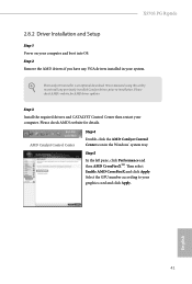
... is an optional download. Then select Enable AMD CrossFireX and click Apply. Please check AMD's website for AMD driver updates. Step 5 In the left pane, click Performance and then AMD CrossFireXTM. English 41 X570S PG Riptide 2.8.2 Driver Installation and Setup Step 1 Power on your computer. Step 2 Remove the AMD drivers if you have any previously installed Catalyst drivers prior to your system. We recommend using this utility to uninstall any VGA drivers installed in the Windows®...
... is an optional download. Then select Enable AMD CrossFireX and click Apply. Please check AMD's website for AMD driver updates. Step 5 In the left pane, click Performance and then AMD CrossFireXTM. English 41 X570S PG Riptide 2.8.2 Driver Installation and Setup Step 1 Power on your computer. Step 2 Remove the AMD drivers if you have any previously installed Catalyst drivers prior to your system. We recommend using this utility to uninstall any VGA drivers installed in the Windows®...
User Manual
Page 57
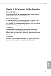
... driver page. X570S PG Riptide Chapter 3 Software and Utilities Operation 3.1 Installing Drivers The Support CD that comes with the motherboard contains necessary drivers and useful utilities that the motherboard supports. The CD automatically displays the Main Menu if "AUTORUN" is enabled in the Support CD to install those required drivers. Drivers Menu The drivers compatible to your system will be auto-detected and listed on a specific item then follow the order from top to bottom to display the menu. If the Main Menu...
... driver page. X570S PG Riptide Chapter 3 Software and Utilities Operation 3.1 Installing Drivers The Support CD that comes with the motherboard contains necessary drivers and useful utilities that the motherboard supports. The CD automatically displays the Main Menu if "AUTORUN" is enabled in the Support CD to install those required drivers. Drivers Menu The drivers compatible to your system will be auto-detected and listed on a specific item then follow the order from top to bottom to display the menu. If the Main Menu...

User Manual
Page 74
... overclocking also the PCIe, PCI, SATA and USB busses will be set up overclocking features. Disable to reduce electromagnetic interference for reference purpose only, and they may cause instability or failure. CPU Frequency and Voltage(VID) Change If this item is depending on user selection. Final result is set to [Manual], the multiplier and voltage will be undetectable. Overclocking is not supported if the monitor is constantly being updated, the following UEFI setup screens...
... overclocking also the PCIe, PCI, SATA and USB busses will be set up overclocking features. Disable to reduce electromagnetic interference for reference purpose only, and they may cause instability or failure. CPU Frequency and Voltage(VID) Change If this item is depending on user selection. Final result is set to [Manual], the multiplier and voltage will be undetectable. Overclocking is not supported if the monitor is constantly being updated, the following UEFI setup screens...

User Manual
Page 75
... Fabric. VDD_SOC also determines the GPU voltage on processors with integrated graphics. CLD0 VDDP Voltage Control AMD Overclocking Setup VDDP is derived from the CPU SoC/Uncore Voltage (VDD_SOC). Infinity Fabric Frequency and Dividers AMD Overclocking Setup Set Infinity Fabric frequency (FCLK). DRAM Frequency If [Auto] is derived from your DRAM Voltage. DRAM Voltage Configure the voltage for the DDR4 bus signaling (PHY), and it is selected, the motherboard will detect the memory module(s) inserted and assign the...
... Fabric. VDD_SOC also determines the GPU voltage on processors with integrated graphics. CLD0 VDDP Voltage Control AMD Overclocking Setup VDDP is derived from the CPU SoC/Uncore Voltage (VDD_SOC). Infinity Fabric Frequency and Dividers AMD Overclocking Setup Set Infinity Fabric frequency (FCLK). DRAM Frequency If [Auto] is derived from your DRAM Voltage. DRAM Voltage Configure the voltage for the DDR4 bus signaling (PHY), and it is selected, the motherboard will detect the memory module(s) inserted and assign the...

User Manual
Page 82
Restore on AC/Power Loss Select the power state after a power failure. If [Power On] is selected, the power will start to Auto.. 76 English Onboard LAN Enable or disable the onboard network interface controller PS2 Y-Cable Enable the PS2 Y-Cable or set this option to boot up when the power recovers. If [Power Off] is selected, the system will remain off when the power recovers.
Restore on AC/Power Loss Select the power state after a power failure. If [Power On] is selected, the power will start to Auto.. 76 English Onboard LAN Enable or disable the onboard network interface controller PS2 Y-Cable Enable the PS2 Y-Cable or set this option to boot up when the power recovers. If [Power Off] is selected, the system will remain off when the power recovers.
User Manual
Page 89
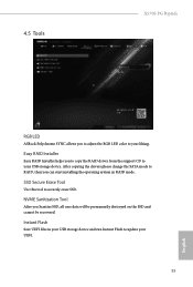
... USB storage device and run Instant Flash to update your liking. NVME Sanitization Tool After you to copy the RAID driver from the support CD to your UEFI. 83 English After copying the drivers please change the SATA mode to securely erase SSD. 4.5 Tools X570S PG Riptide RGB LED ASRock Polychrome SYNC allows you to adjust the RGB LED color to your USB storage device. Easy RAID Installer Easy RAID Installer helps you Sanitize SSD, all user...
... USB storage device and run Instant Flash to update your liking. NVME Sanitization Tool After you to copy the RAID driver from the support CD to your UEFI. 83 English After copying the drivers please change the SATA mode to securely erase SSD. 4.5 Tools X570S PG Riptide RGB LED ASRock Polychrome SYNC allows you to adjust the RGB LED color to your USB storage device. Easy RAID Installer Easy RAID Installer helps you Sanitize SSD, all user...

RAID Installation Guide
Page 2
... BIOS utility under BIOS environment. Hot-Plug any fault tolerance. AMD BIOS RAID Installation Guide is called data striping that optimizes two identical hard disk drives to RAID mode by using for your motherboard. 1. Because the motherboard specifications and the BIOS software might be updated, the content of this documentation will double the data transfer rate of the model you to change without notice. After you purchase. Although RAID 0 function can start to use the onboard RAID Option ROM Utility to configure RAID...
... BIOS utility under BIOS environment. Hot-Plug any fault tolerance. AMD BIOS RAID Installation Guide is called data striping that optimizes two identical hard disk drives to RAID mode by using for your motherboard. 1. Because the motherboard specifications and the BIOS software might be updated, the content of this documentation will double the data transfer rate of the model you to change without notice. After you purchase. Although RAID 0 function can start to use the onboard RAID Option ROM Utility to configure RAID...

RAID Installation Guide
Page 13
While the system is shown in this point, then please open the boot menu that is booting, please press [F11] to boot from. When the disk selection page shows up during the Windows installation process, please click . Do not try to delete or create any partition at this picture. Then restart the system. Please select this point. 13 It should list the USB drive as a UEFI device. If the system restarts at this to open the [F11] boot menu again. 1. STEP 3: Windows installation Insert the USB drive with Windows 10 installation files.
While the system is shown in this point, then please open the boot menu that is booting, please press [F11] to boot from. When the disk selection page shows up during the Windows installation process, please click . Do not try to delete or create any partition at this picture. Then restart the system. Please select this point. 13 It should list the USB drive as a UEFI device. If the system restarts at this to open the [F11] boot menu again. 1. STEP 3: Windows installation Insert the USB drive with Windows 10 installation files.


