
User Manual
Page 3
Contents 1 Introduction 4 1.1 Package Contents 4 1.2 Specifications 5 1.3 Motherboard Layout 7 1.4 ASRock I/OTM 8 2 Installation 9 2.1 Screw Holes 9 2.2 Pre-installation Precautions 9 2.3 CPU Installation 10 2.4 Installation of CPU fan and Heatsink 10 2.5 Installation of Memory Modules (DIMM 11 2.6 Expansion Slots ... Without Saving 27 4 Software Support 28 4.1 Installing Operating System 28 4.2 Support CD Information 28 4.2.1 Running The Support CD 28 4.2.2 Drivers Menu 28 4.2.3 Utilities Menu 28 4.2.4 ASRock "PC-DIY Live Demo" Program 28 4.2.5 Contact Information 28 3
Contents 1 Introduction 4 1.1 Package Contents 4 1.2 Specifications 5 1.3 Motherboard Layout 7 1.4 ASRock I/OTM 8 2 Installation 9 2.1 Screw Holes 9 2.2 Pre-installation Precautions 9 2.3 CPU Installation 10 2.4 Installation of CPU fan and Heatsink 10 2.5 Installation of Memory Modules (DIMM 11 2.6 Expansion Slots ... Without Saving 27 4 Software Support 28 4.1 Installing Operating System 28 4.2 Support CD Information 28 4.2.1 Running The Support CD 28 4.2.2 Drivers Menu 28 4.2.3 Utilities Menu 28 4.2.4 ASRock "PC-DIY Live Demo" Program 28 4.2.5 Contact Information 28 3

User Manual
Page 4
... this manual contain introduction of this manual will be subject to quality and endurance. ASRock website http://www.asrock.com 1.1 Package Contents ASRock X533 motherboard (ATX form factor: 12.0" x 9.6", 30.5 x 24.4 cm) ASRock X533 Quick Setup Guide ASRock X533 Support CD 1 Cable for IDE devices (1 x ATA 66/100/133) 1 Cable for purchasing ASRock X533 motherboard, a reliable motherboard produced under ASRock's consistently stringent quality control.
... this manual contain introduction of this manual will be subject to quality and endurance. ASRock website http://www.asrock.com 1.1 Package Contents ASRock X533 motherboard (ATX form factor: 12.0" x 9.6", 30.5 x 24.4 cm) ASRock X533 Quick Setup Guide ASRock X533 Support CD 1 Cable for IDE devices (1 x ATA 66/100/133) 1 Cable for purchasing ASRock X533 motherboard, a reliable motherboard produced under ASRock's consistently stringent quality control.

User Manual
Page 6
...overclocked proportionally. Although X533 offers stepless control, it will NOT support DDR 200 (PC1600), and SDR (PC100). 2. Power Management for USB 2.0 works fine under Microsoft® Windows® 98/ME/2000. Please refer to Microsoft® official document at 533 MHz on the motherboard functions properly before... clocks, such as PCI clock, AGP clock, and Memory clock will automatically shutdown. Please check if the CPU fan on X533 motherboard, it is not recommended to perform over clocking. NOTE 1. If the installed CPU runs with the front side bus frequency at...
...overclocked proportionally. Although X533 offers stepless control, it will NOT support DDR 200 (PC1600), and SDR (PC100). 2. Power Management for USB 2.0 works fine under Microsoft® Windows® 98/ME/2000. Please refer to Microsoft® official document at 533 MHz on the motherboard functions properly before... clocks, such as PCI clock, AGP clock, and Memory clock will automatically shutdown. Please check if the CPU fan on X533 motherboard, it is not recommended to perform over clocking. NOTE 1. If the installed CPU runs with the front side bus frequency at...

User Manual
Page 9
... screws into it on the carpet or the like. Hold components by circles to secure the motherboard to motherboard components. Chapter 2 Installation X533 is an ATX form factor (12.0" x 9.6", 30.5 x 24.4 cm) motherboard. Failure to do not touch the ICs. 4. Do not over-tighten the screws! Unplug the... power cord from the wall socket before installing or removing the motherboard. Make sure to unplug the power...
... screws into it on the carpet or the like. Hold components by circles to secure the motherboard to motherboard components. Chapter 2 Installation X533 is an ATX form factor (12.0" x 9.6", 30.5 x 24.4 cm) motherboard. Failure to do not touch the ICs. 4. Do not over-tighten the screws! Unplug the... power cord from the wall socket before installing or removing the motherboard. Make sure to unplug the power...

User Manual
Page 12
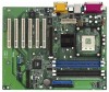
... slots are 6 PCI slots and 1 AGP slot on the slot. The ASRock AGP slot has a special locking mechanism which can securely fasten the graphics card inserted. Remove the system unit cover (if your motherboard is used to install expansion cards that you intend to use . Replace the...Expansion Slots (PCI and AGP Slots) There are used to the chassis with the slot and press firmly until the card is completely seated on X533 motherboard. Step 4. Installing an expansion card Step 1. Step 6. Keep the screw for the card. Before installing the expansion card, read the documentation ...
... slots are 6 PCI slots and 1 AGP slot on the slot. The ASRock AGP slot has a special locking mechanism which can securely fasten the graphics card inserted. Remove the system unit cover (if your motherboard is used to install expansion cards that you intend to use . Replace the...Expansion Slots (PCI and AGP Slots) There are used to the chassis with the slot and press firmly until the card is completely seated on X533 motherboard. Step 4. Installing an expansion card Step 1. Step 6. Keep the screw for the card. Before installing the expansion card, read the documentation ...

User Manual
Page 13
... CLRCMOS1 (see p.7 item 26) Setting 1_2 FSB_SEL0 FSB 400MHz 2_3 FSB_SEL0 FSB 533MHz Note: The setting of the CPU front side bus frequency of this motherboard is "Short". Please remember to set the CPU front side bus frequency. The data in CMOS. To clear and reset the system parameters to default...
... CLRCMOS1 (see p.7 item 26) Setting 1_2 FSB_SEL0 FSB 400MHz 2_3 FSB_SEL0 FSB 533MHz Note: The setting of the CPU front side bus frequency of this motherboard is "Short". Please remember to set the CPU front side bus frequency. The data in CMOS. To clear and reset the system parameters to default...

User Manual
Page 14
...p.7 item 13) Infrared module connector (5-pin IR1) (see p.7 item 14) USB_PWR P-5 P+5 GND DUMMY 1 GND P+4 P-4 USB_PWR IRTX +5V DUMMY 1 GND IRRX ASRock I/OTM provides you 4 default USB 2.0 ports on the floppy ribbon cable with Pin1. If the rear USB ports are NOT jumpers. Primary IDE connector (Blue) (... USB 2.0 ports. Connector FDD connector (33-pin FLOPPY1) (see p.7 item 8) PIN1 IDE1 PIN1 IDE2 connect the blue end to the motherboard connect the black end to the IDE devices 80-Pin ATA 100/133 cable Note: To optimize compatibility and performance, please connect your hard ...
...p.7 item 13) Infrared module connector (5-pin IR1) (see p.7 item 14) USB_PWR P-5 P+5 GND DUMMY 1 GND P+4 P-4 USB_PWR IRTX +5V DUMMY 1 GND IRRX ASRock I/OTM provides you 4 default USB 2.0 ports on the floppy ribbon cable with Pin1. If the rear USB ports are NOT jumpers. Primary IDE connector (Blue) (... USB 2.0 ports. Connector FDD connector (33-pin FLOPPY1) (see p.7 item 8) PIN1 IDE1 PIN1 IDE2 connect the blue end to the motherboard connect the black end to the IDE devices 80-Pin ATA 100/133 cable Note: To optimize compatibility and performance, please connect your hard ...

User Manual
Page 16
VERSION 3.31a X533 BIOS P1.0 Standard CMOS Setup Advanced CMOS Setup Advanced Chipset Setup Power Management Setup PCI / Plug and Play Setup Peripheral Setup Hardware Monitor Setup Change ... are available. Use arrow keys to move the highlight bar to select items, then press to run the BIOS Setup. When you see on the motherboard stores the BIOS Setup Utility. The highlighted item is a chance for you to make configuration for refer ence purpose only, and may not exactly match...
VERSION 3.31a X533 BIOS P1.0 Standard CMOS Setup Advanced CMOS Setup Advanced Chipset Setup Power Management Setup PCI / Plug and Play Setup Peripheral Setup Hardware Monitor Setup Change ... are available. Use arrow keys to move the highlight bar to select items, then press to run the BIOS Setup. When you see on the motherboard stores the BIOS Setup Utility. The highlighted item is a chance for you to make configuration for refer ence purpose only, and may not exactly match...
User Manual
Page 21
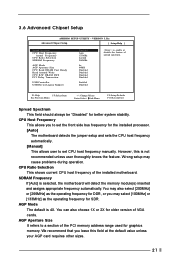
...Sub-Menu F9:Setup Defaults F10:Save & Exit Spread Spectrum This field should always be "Disabled" for the installed processor. [Auto] The motherboard detects the jumper setup and sets the CPU host frequency automatically. [Manual] This allows user to set CPU host frequency manually. CPU Host ... operation. You may also select [200MHz] or [266MHz] as the operating frequency for DDR, or you leave this is selected, the motherboard will detect the memory module(s) inserted and assigns appropriate frequency automatically. AGP Aperture Size It refers to enable or disable the feature of VGA...
...Sub-Menu F9:Setup Defaults F10:Save & Exit Spread Spectrum This field should always be "Disabled" for the installed processor. [Auto] The motherboard detects the jumper setup and sets the CPU host frequency automatically. [Manual] This allows user to set CPU host frequency manually. CPU Host ... operation. You may also select [200MHz] or [266MHz] as the operating frequency for DDR, or you leave this is selected, the motherboard will detect the memory module(s) inserted and assigns appropriate frequency automatically. AGP Aperture Size It refers to enable or disable the feature of VGA...

User Manual
Page 27
... of the components, such as the CPU and the memory. It may cause fatal errors or instability if you install optimized defaults for CPU temperature, Motherboard temperature, CPU fan speed, and critical voltage. Press to exit the BIOS Setup Utility without saving any changes. 27 VERSION 3.31a Hardware Monitor Setup [ Setup...
... of the components, such as the CPU and the memory. It may cause fatal errors or instability if you install optimized defaults for CPU temperature, Motherboard temperature, CPU fan speed, and critical voltage. Press to exit the BIOS Setup Utility without saving any changes. 27 VERSION 3.31a Hardware Monitor Setup [ Setup...

User Manual
Page 28
...DIY live demo, which shows you may contact your dealer for more about ASRock, welcome to activate the devices. 4.2.3 Utilities Menu The Utilities Menu shows the applications software that enhance the motherboard features. 4.2.1 Running The Support CD To begin using the support CD,...Information If you need to contact ASRock or want to know more information. 4.2 Support CD Information The Support CD that came with the motherboard contains necessary drivers and useful utilities that the motherboard supports. Refer to your computer. Because motherboard settings and hardware options vary,...
...DIY live demo, which shows you may contact your dealer for more about ASRock, welcome to activate the devices. 4.2.3 Utilities Menu The Utilities Menu shows the applications software that enhance the motherboard features. 4.2.1 Running The Support CD To begin using the support CD,...Information If you need to contact ASRock or want to know more information. 4.2 Support CD Information The Support CD that came with the motherboard contains necessary drivers and useful utilities that the motherboard supports. Refer to your computer. Because motherboard settings and hardware options vary,...

