User Manual
Page 13
... Certifications • Microsoft® Windows® 10 64-bit • FCC, CE • ErP/EuP ready (ErP/EuP ready power supply is required) * For detailed product information, please visit our website: http://www.asrock.com Please realize that there is a certain risk involved with overclocking, including adjusting the setting in the BIOS, applying...
... Certifications • Microsoft® Windows® 10 64-bit • FCC, CE • ErP/EuP ready (ErP/EuP ready power supply is required) * For detailed product information, please visit our website: http://www.asrock.com Please realize that there is a certain risk involved with overclocking, including adjusting the setting in the BIOS, applying...

User Manual
Page 36
...X470 Master SLI/ac / X470 Master SLI 2.4 Expansion Slots (PCI Express Slots) There are 6 PCI Express slots on the motherboard. PCIE2 (PCIe 2.0 x1 slot) is used for PCI Express x1 lane width cards. PCIE5 (PCIe 2.0 x1 slot) is unplugged. Please read the documentation of the expansion card and make sure that the power supply... is switched off or the power cord is used for PCI Express x1 lane width cards. PCIE3 (PCIe 2.0 x1 slot) is used for the card ...
...X470 Master SLI/ac / X470 Master SLI 2.4 Expansion Slots (PCI Express Slots) There are 6 PCI Express slots on the motherboard. PCIE2 (PCIe 2.0 x1 slot) is used for PCI Express x1 lane width cards. PCIE5 (PCIe 2.0 x1 slot) is unplugged. Please read the documentation of the expansion card and make sure that the power supply... is switched off or the power cord is used for PCI Express x1 lane width cards. PCIE3 (PCIe 2.0 x1 slot) is used for the card ...
User Manual
Page 37
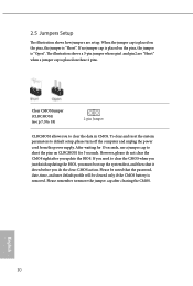
... do the clear-CMOS action. Please remember toremove the jumper cap after you to default setup, please turn off the computer and unplug the power cord from the power supply. 2.5 Jumpers Setup The illustration shows how jumpers are "Short" when a jumper cap is removed. If no jumper cap is placed on CLRCMOS1 for...
... do the clear-CMOS action. Please remember toremove the jumper cap after you to default setup, please turn off the computer and unplug the power cord from the power supply. 2.5 Jumpers Setup The illustration shows how jumpers are "Short" when a jumper cap is removed. If no jumper cap is placed on CLRCMOS1 for...
User Manual
Page 41
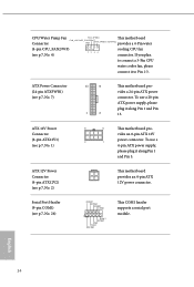
... ATX12V1) (see p.7, No. 2) This motherboard provides an 4-pin ATX 12V power connector. English 34 ATX 12V Power Connector (4-pin ATX12V2) (see p.7, No. 1) 8 5 This motherboard pro- To use a 20-pin ATX power supply, please plug it along Pin 1 and Pin 5. vides an 8-pin ATX 12V 4 1 power connector. Serial Port Header (9-pin COM1) (see p.7, No. 4) connector. CPU...
... ATX12V1) (see p.7, No. 2) This motherboard provides an 4-pin ATX 12V power connector. English 34 ATX 12V Power Connector (4-pin ATX12V2) (see p.7, No. 1) 8 5 This motherboard pro- To use a 20-pin ATX power supply, please plug it along Pin 1 and Pin 5. vides an 8-pin ATX 12V 4 1 power connector. Serial Port Header (9-pin COM1) (see p.7, No. 4) connector. CPU...
User Manual
Page 44
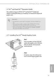
... and the other graphics card to two identical PCI Express x16 graphics cards. Make sure that your power supply unit (PSU) can provide at least the minimum power your graphics card driver supports NVIDIA® SLITM technology. X470 Master SLI/ac / X470 Master SLI 2.7 SLITM and Quad SLITM Operation Guide This motherboard supports NVIDIA® SLITM and Quad SLITM (Scalable...
... and the other graphics card to two identical PCI Express x16 graphics cards. Make sure that your power supply unit (PSU) can provide at least the minimum power your graphics card driver supports NVIDIA® SLITM technology. X470 Master SLI/ac / X470 Master SLI 2.7 SLITM and Quad SLITM Operation Guide This motherboard supports NVIDIA® SLITM and Quad SLITM (Scalable...
User Manual
Page 47
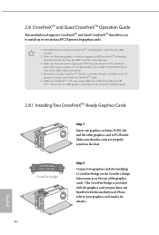
... mode. 5. Different CrossFireXTM cards may require different methods to your graphics card vendor for details.) English 40 Make sure that your power supply unit (PSU) can provide at least the minimum power your graphics card driver supports AMD CrossFireXTM technology. CrossFire Bridge Step 2 Connect two graphics cards by installing a CrossFire Bridge on the...
... mode. 5. Different CrossFireXTM cards may require different methods to your graphics card vendor for details.) English 40 Make sure that your power supply unit (PSU) can provide at least the minimum power your graphics card driver supports AMD CrossFireXTM technology. CrossFire Bridge Step 2 Connect two graphics cards by installing a CrossFire Bridge on the...
User Manual
Page 66
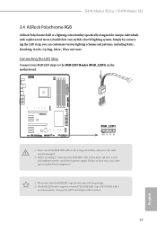
X470 Master SLI/ac / X470 Master SLI 3.4 ASRock Polychrome RGB ASRock Polychrome RGB is a lighting control utility specifically designed for unique individuals with the package. 2. Simply by connecting the LED strip, you can customize various lighting schemes and patterns, including Static, Breathing, Strobe, Cycling, Music, Wave and more. Before installing or removing your RGB LED cable, please power... (12V/G/R/B), with a maximum power rating of 3A (12V) and length within 2 meters. 59 English Connecting the LED Strip Connect your system and unplug the power cord from the power supply.
X470 Master SLI/ac / X470 Master SLI 3.4 ASRock Polychrome RGB ASRock Polychrome RGB is a lighting control utility specifically designed for unique individuals with the package. 2. Simply by connecting the LED strip, you can customize various lighting schemes and patterns, including Static, Breathing, Strobe, Cycling, Music, Wave and more. Before installing or removing your RGB LED cable, please power... (12V/G/R/B), with a maximum power rating of 3A (12V) and length within 2 meters. 59 English Connecting the LED Strip Connect your system and unplug the power cord from the power supply.
User Manual
Page 67
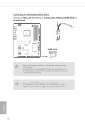
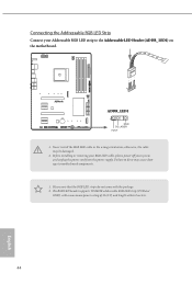
... your Addressable RGB LED strip to motherboard components. 1. Connecting the Addressable RGB LED Strip Connect your system and unplug the power cord from the power supply. otherwise, the cable may cause damages to the Addressable LED Header (ADDR_LED1) on the motherboard. 1 ADDR_LED1 1 GND DO_ADDR VOUT 1. Never install the RGB LED cable ...
... your Addressable RGB LED strip to motherboard components. 1. Connecting the Addressable RGB LED Strip Connect your system and unplug the power cord from the power supply. otherwise, the cable may cause damages to the Addressable LED Header (ADDR_LED1) on the motherboard. 1 ADDR_LED1 1 GND DO_ADDR VOUT 1. Never install the RGB LED cable ...
User Manual
Page 76
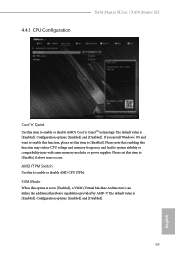
... option is set this function may reduce CPU voltage and memory frequency, and lead to system stability or compatibility issue with some memory modules or power supplies. Configuration options: [Enabled] and [Disabled]. Please note that enabling this item to [Enabled]. If you install Windows® OS and want to enable...Switch Use this item to enable or disable AMD's Cool 'n' QuietTM technology. The default value is [Enabled]. The default value is [Enabled]. 4.4.1 CPU Configuration X470 Master SLI/ac / X470 Master SLI Cool 'n' Quiet Use this to enable or disable AMD CPU fTPM.
... option is set this function may reduce CPU voltage and memory frequency, and lead to system stability or compatibility issue with some memory modules or power supplies. Configuration options: [Enabled] and [Disabled]. Please note that enabling this item to [Enabled]. If you install Windows® OS and want to enable...Switch Use this item to enable or disable AMD's Cool 'n' QuietTM technology. The default value is [Enabled]. The default value is [Enabled]. 4.4.1 CPU Configuration X470 Master SLI/ac / X470 Master SLI Cool 'n' Quiet Use this to enable or disable AMD CPU fTPM.
Quick Installation Guide
Page 17
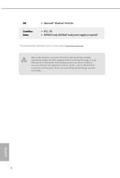
... are not responsible for possible damage caused by overclocking. X470 Master SLI/ac / X470 Master SLI OS Certifications • Microsoft® Windows® 10 64-bit • FCC, CE • ErP/EuP ready (ErP/EuP ready power supply is required) * For detailed product information, please visit our website: http://www.asrock.com Please realize that there is a certain risk involved...
... are not responsible for possible damage caused by overclocking. X470 Master SLI/ac / X470 Master SLI OS Certifications • Microsoft® Windows® 10 64-bit • FCC, CE • ErP/EuP ready (ErP/EuP ready power supply is required) * For detailed product information, please visit our website: http://www.asrock.com Please realize that there is a certain risk involved...
Quick Installation Guide
Page 33
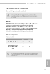
... the expansion card and make sure that the power supply is switched off or the power cord is used for PCI Express x16 lane width graphics cards. PCIE3 (PCIe 2.0 x1 slot) is unplugged. PCIE6 (PCIe 2.0 x1 slot) is used for PCI Express x1 lane width cards. X470 Master SLI/ac / X470 Master SLI 2.4 Expansion Slots (PCI Express Slots) There are...
... the expansion card and make sure that the power supply is switched off or the power cord is used for PCI Express x16 lane width graphics cards. PCIE3 (PCIe 2.0 x1 slot) is unplugged. PCIE6 (PCIe 2.0 x1 slot) is used for PCI Express x1 lane width cards. X470 Master SLI/ac / X470 Master SLI 2.4 Expansion Slots (PCI Express Slots) There are...

Quick Installation Guide
Page 34
... CMOS Jumper (CLRCMOS1) (see p.1, No. 18) 2-pin Jumper CLRCMOS1 allows you need to default setup, please turn off the computer and unplug the power cord from the power supply. If you to short the pins on the pins, the jumper is "Open". Please remember toremove the jumper cap after you do not clear...
... CMOS Jumper (CLRCMOS1) (see p.1, No. 18) 2-pin Jumper CLRCMOS1 allows you need to default setup, please turn off the computer and unplug the power cord from the power supply. If you to short the pins on the pins, the jumper is "Open". Please remember toremove the jumper cap after you do not clear...
Quick Installation Guide
Page 38
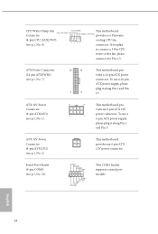
To use a 4 1 4-pin ATX power supply, please plug it along Pin 1 and Pin 5. Serial Port Header (9-pin COM1) (see p.1, No. 7) 12 24 1 13 This motherboard provides a 24-pin ATX power connector. ATX Power Connector (24-pin ATXPWR1) (see p.1, No. 26) RRXD1 DDTR#1 DDSR#1 CCTS#1 1 RRI#1 .../WP) cooling CPU fan (see p.1, No. 2) This motherboard provides an 4-pin ATX 12V power connector. ATX 12V Power Connector (4-pin ATX12V2) (see p.1, No. 4) connector. To use a 20-pin ATX power supply, please plug it along Pin 1 and Pin 13. If you plan to connect a 3-Pin...
To use a 4 1 4-pin ATX power supply, please plug it along Pin 1 and Pin 5. Serial Port Header (9-pin COM1) (see p.1, No. 7) 12 24 1 13 This motherboard provides a 24-pin ATX power connector. ATX Power Connector (24-pin ATXPWR1) (see p.1, No. 26) RRXD1 DDTR#1 DDSR#1 CCTS#1 1 RRI#1 .../WP) cooling CPU fan (see p.1, No. 2) This motherboard provides an 4-pin ATX 12V power connector. ATX 12V Power Connector (4-pin ATX12V2) (see p.1, No. 4) connector. To use a 20-pin ATX power supply, please plug it along Pin 1 and Pin 13. If you plan to connect a 3-Pin...

Quick Installation Guide
Page 47
X470 Master SLI/ac / X470 Master SLI 2.9 ASRock Polychrome RGB ASRock Polychrome RGB is a lighting control utility specifically designed for unique individuals with sophisticated tastes to motherboard components. 1. Before installing or removing your RGB LED cable, please power off your RGB LED strips to the RGB LED Header (RGB_LED1) on the ...strips do so may be damaged. 2. Connecting the LED Strip Connect your system and unplug the power cord from the power supply. Simply by connecting the LED strip, you can customize various lighting schemes and patterns, including ...
X470 Master SLI/ac / X470 Master SLI 2.9 ASRock Polychrome RGB ASRock Polychrome RGB is a lighting control utility specifically designed for unique individuals with sophisticated tastes to motherboard components. 1. Before installing or removing your RGB LED cable, please power off your RGB LED strips to the RGB LED Header (RGB_LED1) on the ...strips do so may be damaged. 2. Connecting the LED Strip Connect your system and unplug the power cord from the power supply. Simply by connecting the LED strip, you can customize various lighting schemes and patterns, including ...
Quick Installation Guide
Page 48
Connecting the Addressable RGB LED Strip Connect your system and unplug the power cord from the power supply. Failure to do not come with a maximum power rating of 3A (5V) and length within 2 meters. 44 English otherwise, the cable may cause damages to the Addressable LED Header (ADDR_LED1) on the motherboard. 1 ...
Connecting the Addressable RGB LED Strip Connect your system and unplug the power cord from the power supply. Failure to do not come with a maximum power rating of 3A (5V) and length within 2 meters. 44 English otherwise, the cable may cause damages to the Addressable LED Header (ADDR_LED1) on the motherboard. 1 ...

