WiFi Installation Guide
Page 1
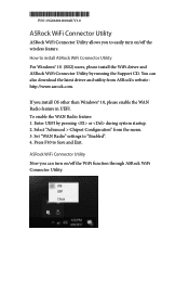
... > Chipset Configuration" from ASRock's website : http://www.asrock.com. Press F10 to "Enabled". 4. How to easily turn on /off the WiFi function through ASRock WiFi Connector Utility. ASRock WiFi Connector Utility Now you can also download the latest driver and utility from the menu. 3. If you install OS other than Windows® 10, please enable the WAN Radio feature in UEFI. Enter UEFI by running the Support CD. *15G062041100AK* P/N: 15G062041100AK V1.0 ASRock WiFi Connector Utility ASRock WiFi Connector Utility...
... > Chipset Configuration" from ASRock's website : http://www.asrock.com. Press F10 to "Enabled". 4. How to easily turn on /off the WiFi function through ASRock WiFi Connector Utility. ASRock WiFi Connector Utility Now you can also download the latest driver and utility from the menu. 3. If you install OS other than Windows® 10, please enable the WAN Radio feature in UEFI. Enter UEFI by running the Support CD. *15G062041100AK* P/N: 15G062041100AK V1.0 ASRock WiFi Connector Utility ASRock WiFi Connector Utility...

RAID Installation Guide
Page 2
... hard disk drives to set . After you make a SATA driver diskette, press or to enter BIOS setup to read and write data in parallel, interleaved stacks. It will improve data access and storage since the disk array management software will cause data damage or data loss. RAID 1 (Data Mirroring) RAID 1 is a method combining two or more hard disk drives into one drive fails. 2 Although RAID 0 function can start to use the onboard RAID Option ROM Utility to configure RAID...
... hard disk drives to set . After you make a SATA driver diskette, press or to enter BIOS setup to read and write data in parallel, interleaved stacks. It will improve data access and storage since the disk array management software will cause data damage or data loss. RAID 1 (Data Mirroring) RAID 1 is a method combining two or more hard disk drives into one drive fails. 2 Although RAID 0 function can start to use the onboard RAID Option ROM Utility to configure RAID...

RAID Installation Guide
Page 8
... the configuration. D. Insert the Support CD into one of the USB port. B. STEP 3.1: Copy RAID driver to a USB flash drive You can choose either STEP 3.1 or STEP 3.2 to enter UEFI setup utility. A. Click to find the driver inside your USB flash disk. Please install the DVD-ROM. Go to finish the driver copy process. STEP 3.2: Download driver from ASRock's website and unzip the file into your USB flash drive. 8 C. During Windows installation process, when Disk selection page show up, please click . Plug a USB drive...
... the configuration. D. Insert the Support CD into one of the USB port. B. STEP 3.1: Copy RAID driver to a USB flash drive You can choose either STEP 3.1 or STEP 3.2 to enter UEFI setup utility. A. Click to find the driver inside your USB flash disk. Please install the DVD-ROM. Go to finish the driver copy process. STEP 3.2: Download driver from ASRock's website and unzip the file into your USB flash drive. 8 C. During Windows installation process, when Disk selection page show up, please click . Plug a USB drive...

RAID Installation Guide
Page 12
... the configuration. STEP 2.1: Copy RAID driver to a USB flash drive You can choose either STEP2.1 or STEP2.2 to exit. Please install the DVD-ROM. Follow instructions to enter UEFI setup utility. H. A. During system boot, press or key to finish the driver copy process. Plug a USB drive into your USB flash disk. 12 Please download the "SATA Floppy Imaged driver" from ASRock's website A. G. STEP 2.2: Download driver from ASRock's website and unzip the file into one of the USB port. Insert the Support CD into the DVD-ROM drive. D. E. Go...
... the configuration. STEP 2.1: Copy RAID driver to a USB flash drive You can choose either STEP2.1 or STEP2.2 to exit. Please install the DVD-ROM. Follow instructions to enter UEFI setup utility. H. A. During system boot, press or key to finish the driver copy process. Plug a USB drive into your USB flash disk. 12 Please download the "SATA Floppy Imaged driver" from ASRock's website A. G. STEP 2.2: Download driver from ASRock's website and unzip the file into one of the USB port. Insert the Support CD into the DVD-ROM drive. D. E. Go...

Quick Installation Guide
Page 11
...PCI Express module up to Gen3 x4 (32 Gb/s)* * Supports NVMe RAID (RAID 0, RAID 1 and RAID 10) * Supports NVMe SSD as boot disks * Supports ASRock U.2 Kit • 1 x U.2 Connector * If U.2 Connector is plugged, M2_1 will be disabled Connector • 1 x TPM Header • 1 x Power LED and Speaker Header • 1 x RGB LED Header * Supports in total up to 12V/3A, 36W LED Strip • 1 x CPU Fan Connector (4-pin) * The CPU Fan Connector supports the CPU fan of maximum 1A (12W) fan power. • 1 x CPU Optional/Water Pump Fan Connector (4-pin) (Smart Fan Speed Control) * The CPU Optional...
...PCI Express module up to Gen3 x4 (32 Gb/s)* * Supports NVMe RAID (RAID 0, RAID 1 and RAID 10) * Supports NVMe SSD as boot disks * Supports ASRock U.2 Kit • 1 x U.2 Connector * If U.2 Connector is plugged, M2_1 will be disabled Connector • 1 x TPM Header • 1 x Power LED and Speaker Header • 1 x RGB LED Header * Supports in total up to 12V/3A, 36W LED Strip • 1 x CPU Fan Connector (4-pin) * The CPU Fan Connector supports the CPU fan of maximum 1A (12W) fan power. • 1 x CPU Optional/Water Pump Fan Connector (4-pin) (Smart Fan Speed Control) * The CPU Optional...

Quick Installation Guide
Page 12
... of the audio connectors. • 2 x USB 2.0 Headers (Support 4 USB 2.0 ports) (Supports ESD Protection) • 2 x USB 3.1 Gen1 Headers (Support 4 USB 3.1 Gen1 ports) (Supports ESD Protection) • 1 x Clear CMOS Button • 1 x Dr. Debug with LED • 1 x Power Button • 1 x Reset Button • 1 x CPU Xtreme OC Switch • AMI UEFI Legal BIOS with GUI support • Supports "Plug and Play" • ACPI 5.1 compliance wake up events • Supports jumperfree • SMBIOS 2.3 support • CPU, VCORE_NB, DRAM, VPPM, PCH 1.05V, +1.8V, VDDP, PROM 2.5V, Voltage Multi...
... of the audio connectors. • 2 x USB 2.0 Headers (Support 4 USB 2.0 ports) (Supports ESD Protection) • 2 x USB 3.1 Gen1 Headers (Support 4 USB 3.1 Gen1 ports) (Supports ESD Protection) • 1 x Clear CMOS Button • 1 x Dr. Debug with LED • 1 x Power Button • 1 x Reset Button • 1 x CPU Xtreme OC Switch • AMI UEFI Legal BIOS with GUI support • Supports "Plug and Play" • ACPI 5.1 compliance wake up events • Supports jumperfree • SMBIOS 2.3 support • CPU, VCORE_NB, DRAM, VPPM, PCH 1.05V, +1.8V, VDDP, PROM 2.5V, Voltage Multi...

Quick Installation Guide
Page 32
... BIOS Flashback Button for three seconds. Then plug your USB flash drive must be FAT32. 3. Please follow the steps below. 1. Extract BIOS file from ASRock's website : http://www.asrock.com. 2. USB BIOS Flashback port English 29 X399M Taichi BIOS Flashback Button (BIOS_FB1) (see p.3, No. 17) BIOS Flashback Button allows users to blink. 8. Then the LED starts to flash the BIOS. To use USB BIOS Flashback function, press the BIOS Flashback Button for about three seconds. Rename the file to "creative.rom...
... BIOS Flashback Button for three seconds. Then plug your USB flash drive must be FAT32. 3. Please follow the steps below. 1. Extract BIOS file from ASRock's website : http://www.asrock.com. 2. USB BIOS Flashback port English 29 X399M Taichi BIOS Flashback Button (BIOS_FB1) (see p.3, No. 17) BIOS Flashback Button allows users to blink. 8. Then the LED starts to flash the BIOS. To use USB BIOS Flashback function, press the BIOS Flashback Button for about three seconds. Rename the file to "creative.rom...
Quick Installation Guide
Page 33
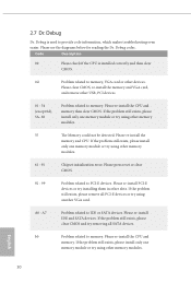
... clear CMOS. 0d Problem related to memory, VGA card or other devices. Please re-install the CPU and memory then clear CMOS. If the problem still exists, please install only one memory module or try using other slots. A7 Problem related to PCI-E devices. Please re-install IDE and SATA devices. Please re-install the CPU and memory. If the problem still exists, please remove all PCI-E devices or try removing all SATA devices. Please press reset or clear CMOS. 92 - 99 Problem related to IDE or SATA devices. If the problem...
... clear CMOS. 0d Problem related to memory, VGA card or other devices. Please re-install the CPU and memory then clear CMOS. If the problem still exists, please install only one memory module or try using other slots. A7 Problem related to PCI-E devices. Please re-install IDE and SATA devices. Please re-install the CPU and memory. If the problem still exists, please remove all PCI-E devices or try removing all SATA devices. Please press reset or clear CMOS. 92 - 99 Problem related to IDE or SATA devices. If the problem...
User Manual
Page 9
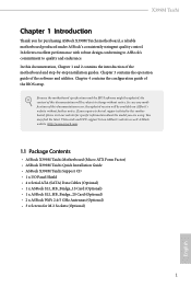
... Sockets (Optional) 1 English You may find the latest VGA cards and CPU support list on ASRock's website without notice. In this motherboard, please visit our website for specific information about the model you are using. ASRock website http://www.asrock.com. 1.1 Package Contents • ASRock X399M Taichi Motherboard (Micro ATX Form Factor) • ASRock X399M Taichi Quick Installation Guide • ASRock X399M Taichi Support CD • 1 x I/O Panel Shield • 4 x Serial ATA (SATA) Data Cables (Optional) • 1 x ASRock SLI_HB_Bridge_1S Card (Optional) • 1 x ASRock...
... Sockets (Optional) 1 English You may find the latest VGA cards and CPU support list on ASRock's website without notice. In this motherboard, please visit our website for specific information about the model you are using. ASRock website http://www.asrock.com. 1.1 Package Contents • ASRock X399M Taichi Motherboard (Micro ATX Form Factor) • ASRock X399M Taichi Quick Installation Guide • ASRock X399M Taichi Support CD • 1 x I/O Panel Shield • 4 x Serial ATA (SATA) Data Cables (Optional) • 1 x ASRock SLI_HB_Bridge_1S Card (Optional) • 1 x ASRock...

User Manual
Page 12
...PCI Express module up to Gen3 x4 (32 Gb/s)* * Supports NVMe RAID (RAID 0, RAID 1 and RAID 10) * Supports NVMe SSD as boot disks * Supports ASRock U.2 Kit • 1 x U.2 Connector * If U.2 Connector is plugged, M2_1 will be disabled Connector • 1 x TPM Header • 1 x Power LED and Speaker Header • 1 x RGB LED Header * Supports in total up to 12V/3A, 36W LED Strip • 1 x CPU Fan Connector (4-pin) * The CPU Fan Connector supports the CPU fan of maximum 1A (12W) fan power. • 1 x CPU Optional/Water Pump Fan Connector (4-pin) (Smart Fan Speed Control) * The CPU Optional...
...PCI Express module up to Gen3 x4 (32 Gb/s)* * Supports NVMe RAID (RAID 0, RAID 1 and RAID 10) * Supports NVMe SSD as boot disks * Supports ASRock U.2 Kit • 1 x U.2 Connector * If U.2 Connector is plugged, M2_1 will be disabled Connector • 1 x TPM Header • 1 x Power LED and Speaker Header • 1 x RGB LED Header * Supports in total up to 12V/3A, 36W LED Strip • 1 x CPU Fan Connector (4-pin) * The CPU Fan Connector supports the CPU fan of maximum 1A (12W) fan power. • 1 x CPU Optional/Water Pump Fan Connector (4-pin) (Smart Fan Speed Control) * The CPU Optional...

User Manual
Page 13
...audio connectors. • 2 x USB 2.0 Headers (Support 4 USB 2.0 ports) (Supports ESD Protection) • 2 x USB 3.1 Gen1 Headers (Support 4 USB 3.1 Gen1 ports) (Supports ESD Protection) • 1 x Clear CMOS Button • 1 x Dr. Debug with LED • 1 x Power Button • 1 x Reset Button • 1 x CPU Xtreme OC Switch BIOS Feature • AMI UEFI Legal BIOS with GUI support • Supports "Plug and Play" • ACPI 5.1 compliance wake up events • Supports jumperfree • SMBIOS 2.3 support • CPU, VCORE_NB, DRAM, VPPM, PCH 1.05V, +1.8V, VDDP, PROM 2.5V, Voltage...
...audio connectors. • 2 x USB 2.0 Headers (Support 4 USB 2.0 ports) (Supports ESD Protection) • 2 x USB 3.1 Gen1 Headers (Support 4 USB 3.1 Gen1 ports) (Supports ESD Protection) • 1 x Clear CMOS Button • 1 x Dr. Debug with LED • 1 x Power Button • 1 x Reset Button • 1 x CPU Xtreme OC Switch BIOS Feature • AMI UEFI Legal BIOS with GUI support • Supports "Plug and Play" • ACPI 5.1 compliance wake up events • Supports jumperfree • SMBIOS 2.3 support • CPU, VCORE_NB, DRAM, VPPM, PCH 1.05V, +1.8V, VDDP, PROM 2.5V, Voltage...

User Manual
Page 37
... the LED light turns solid green, this means that the BIOS Flashback is not operating properly. USB BIOS Flashback port English 29 Then plug your USB flash drive must be FAT32. 3. Please follow the steps below. 1. Rename the file to your USB flash drive.Please make sure the file system of X: USB flash drive. 5. Extract BIOS file from ASRock's website : http://www.asrock.com. 2. X399M Taichi BIOS Flashback Button (BIOS_FB1) (see p.9, No. 17) BIOS Flashback Button allows users to blink...
... the LED light turns solid green, this means that the BIOS Flashback is not operating properly. USB BIOS Flashback port English 29 Then plug your USB flash drive must be FAT32. 3. Please follow the steps below. 1. Rename the file to your USB flash drive.Please make sure the file system of X: USB flash drive. 5. Extract BIOS file from ASRock's website : http://www.asrock.com. 2. X399M Taichi BIOS Flashback Button (BIOS_FB1) (see p.9, No. 17) BIOS Flashback Button allows users to blink...

User Manual
Page 38
...-install IDE and SATA devices. English 30 Please re-install the memory and CPU. b0 Problem related to PCI-E devices. Please re-install the CPU and memory. Please re-install the CPU and memory then clear CMOS. Please press reset or clear CMOS. 92 - 99 Problem related to memory. If the problem still exists, please install only one memory module or try using another VGA card. If the problem still exists, please clear CMOS and try using other slots. If the problem still exists, please remove...
...-install IDE and SATA devices. English 30 Please re-install the memory and CPU. b0 Problem related to PCI-E devices. Please re-install the CPU and memory. Please re-install the CPU and memory then clear CMOS. Please press reset or clear CMOS. 92 - 99 Problem related to memory. If the problem still exists, please install only one memory module or try using another VGA card. If the problem still exists, please clear CMOS and try using other slots. If the problem still exists, please remove...

User Manual
Page 41
Step 4 Connect a VGA cable or a DVI cable to the monitor connector or the DVI connector of the graphics card that is firmly in place. Make sure the ASRock SLI_ HB_Bridge_1S Card is inserted to PCIE1 slot. Make sure the ASRock SLI_ HB_Bridge_2S Card is firmly in place. X399M Taichi Step 3 When the graphics cards are installed on PCIE1 and PCIE3: Align and insert the ASRock SLI_HB_ Bridge_2S Card to the goldfingers on...
Step 4 Connect a VGA cable or a DVI cable to the monitor connector or the DVI connector of the graphics card that is firmly in place. Make sure the ASRock SLI_ HB_Bridge_1S Card is inserted to PCIE1 slot. Make sure the ASRock SLI_ HB_Bridge_2S Card is firmly in place. X399M Taichi Step 3 When the graphics cards are installed on PCIE1 and PCIE3: Align and insert the ASRock SLI_HB_ Bridge_2S Card to the goldfingers on...

User Manual
Page 43
... to AMD graphics card manuals for detailed installation guide. 2.9.1 Installing Two CrossFireXTM-Ready Graphics Cards Step 1 Insert one graphics card into PCIE1 slot and the other graphics card to two identical PCI Express x16 graphics cards. 1. X399M Taichi 2.9 CrossFireXTM and Quad CrossFireXTM Operation Guide This motherboard supports CrossFireXTM and Quad CrossFireXTM that allows you to install up to PCIE2 or PCIE3 slot. You should only use a AMD certified PSU. Please refer to use identical CrossFireXTM-ready graphics cards that your graphics card driver supports AMD...
... to AMD graphics card manuals for detailed installation guide. 2.9.1 Installing Two CrossFireXTM-Ready Graphics Cards Step 1 Insert one graphics card into PCIE1 slot and the other graphics card to two identical PCI Express x16 graphics cards. 1. X399M Taichi 2.9 CrossFireXTM and Quad CrossFireXTM Operation Guide This motherboard supports CrossFireXTM and Quad CrossFireXTM that allows you to install up to PCIE2 or PCIE3 slot. You should only use a AMD certified PSU. Please refer to use identical CrossFireXTM-ready graphics cards that your graphics card driver supports AMD...
User Manual
Page 45
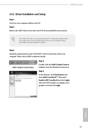
... is an optional download. Please check AMD's website for AMD driver updates. Then select Enable AMD CrossFireX and click Apply. Step 2 Remove the AMD drivers if you have any previously installed Catalyst drivers prior to installation. Step 3 Install the required drivers and CATALYST Control Center then restart your graphics card and click Apply. Select the GPU number according to uninstall any VGA drivers installed in the Windows® system tray. X399M Taichi 2.9.2 Driver Installation and Setup Step 1 Power on...
... is an optional download. Please check AMD's website for AMD driver updates. Then select Enable AMD CrossFireX and click Apply. Step 2 Remove the AMD drivers if you have any previously installed Catalyst drivers prior to installation. Step 3 Install the required drivers and CATALYST Control Center then restart your graphics card and click Apply. Select the GPU number according to uninstall any VGA drivers installed in the Windows® system tray. X399M Taichi 2.9.2 Driver Installation and Setup Step 1 Power on...

User Manual
Page 56
... be auto-detected and listed on the file "ASRSETUP.EXE" in your CD-ROM drive. If the Main Menu does not appear automatically, locate and double click on the support CD driver page. Click on a specific item then follow the order from top to bottom to display the menu. Utilities Menu The Utilities Menu shows the application software that enhance the motherboard's features. Running The Support CD To begin using the support...
... be auto-detected and listed on the file "ASRSETUP.EXE" in your CD-ROM drive. If the Main Menu does not appear automatically, locate and double click on the support CD driver page. Click on a specific item then follow the order from top to bottom to display the menu. Utilities Menu The Utilities Menu shows the application software that enhance the motherboard's features. Running The Support CD To begin using the support...

User Manual
Page 81
PS2 Y-Cable Enable the PS2 Y-Cable or set this option to Auto. 73 English Serial Port Address Select the address of the Serial port. 4.6.5 Super IO Configuration X399M Taichi Serial Port Enable or disable the Serial port.
PS2 Y-Cable Enable the PS2 Y-Cable or set this option to Auto. 73 English Serial Port Address Select the address of the Serial port. 4.6.5 Super IO Configuration X399M Taichi Serial Port Enable or disable the Serial port.

User Manual
Page 86
To re-enable SMT, a POWER CYCLE is the number of cores to be used . DF Common Options DRAM scrub time Provide a value that is needed after selecting the 'Auto' option. Core/Thread Enablement Downcore control Sets the number of hours to disable symmetric multithreading. Streaming Stores Control Enables or disables the streaming stores functionality. OC Mode OC1 - 16 cores/3.6GHz on 1.3375V OC2 - 8 cores/3.7GHz on 1.369V OC3 - 4 cores/3.75GHz on...
To re-enable SMT, a POWER CYCLE is the number of cores to be used . DF Common Options DRAM scrub time Provide a value that is needed after selecting the 'Auto' option. Core/Thread Enablement Downcore control Sets the number of hours to disable symmetric multithreading. Streaming Stores Control Enables or disables the streaming stores functionality. OC Mode OC1 - 16 cores/3.6GHz on 1.3375V OC2 - 8 cores/3.7GHz on 1.369V OC3 - 4 cores/3.75GHz on...
User Manual
Page 94
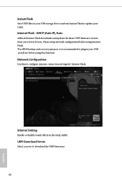
...BIOS backup and recovery purpose, it is recommended to plug in the setup utility. DHCP (Auto IP), Auto ASRock Internet Flash downloads and updates the latest UEFI firmware version from our servers for Internet Flash. Internet Flash - UEFI Download Server Select a server to download the UEFI firmware. 86 English Network Configuration Use this function. Internet Setting Enable or disable sound effects in your UEFI. Instant Flash Save UEFI files in your USB storage device and run Instant Flash to update your USB pen drive before using this to configure internet connection settings...
...BIOS backup and recovery purpose, it is recommended to plug in the setup utility. DHCP (Auto IP), Auto ASRock Internet Flash downloads and updates the latest UEFI firmware version from our servers for Internet Flash. Internet Flash - UEFI Download Server Select a server to download the UEFI firmware. 86 English Network Configuration Use this function. Internet Setting Enable or disable sound effects in your UEFI. Instant Flash Save UEFI files in your USB storage device and run Instant Flash to update your USB pen drive before using this to configure internet connection settings...


