RAID Installation Guide
Page 2
... "User Manual" in our support CD, then you make a SATA driver diskette, press or to enter BIOS setup to set . For optimal performance, please install identical drives of the data in parallel, interleaved stacks. RAID 0 (Data Striping) RAID 0 is an instruction for "Redundant Array of the RAID 0 Disk will cause data damage or data loss. AMD BIOS RAID Installation Guide AMD BIOS RAID Installation Guide is called data mirroring that optimizes two identical hard disk drives to RAID mode by using the onboard...
... "User Manual" in our support CD, then you make a SATA driver diskette, press or to enter BIOS setup to set . For optimal performance, please install identical drives of the data in parallel, interleaved stacks. RAID 0 (Data Striping) RAID 0 is an instruction for "Redundant Array of the RAID 0 Disk will cause data damage or data loss. AMD BIOS RAID Installation Guide AMD BIOS RAID Installation Guide is called data mirroring that optimizes two identical hard disk drives to RAID mode by using the onboard...

RAID Installation Guide
Page 8
... the Support CD into one of the USB port. Go to finish the driver copy process. STEP 4: Windows installation A. Click to find the driver inside your USB flash disk. A. Plug a USB drive into the DVD-ROM drive. E. Please download the "SATA Floppy Imaged driver" from ASRock's website A. B. C. Follow instructions to Tools Easy RAID Installer F. During system boot, press or key to finish the configuration. B. During Windows installation process, when Disk selection page show up, please click . STEP 3.1: Copy RAID driver to a USB flash drive...
... the Support CD into one of the USB port. Go to finish the driver copy process. STEP 4: Windows installation A. Click to find the driver inside your USB flash disk. A. Plug a USB drive into the DVD-ROM drive. E. Please download the "SATA Floppy Imaged driver" from ASRock's website A. B. C. Follow instructions to Tools Easy RAID Installer F. During system boot, press or key to finish the configuration. B. During Windows installation process, when Disk selection page show up, please click . STEP 3.1: Copy RAID driver to a USB flash drive...

RAID Installation Guide
Page 12
... configuration. STEP 2.1: Copy RAID driver to a USB flash drive You can choose either STEP2.1 or STEP2.2 to Tools Easy RAID Installer F. E. STEP 2.2: Download driver from ASRock's website and unzip the file into your USB flash disk. 12 A. During system boot, press or key to finish the driver copy process. Plug a USB drive into the DVD-ROM drive. D. Follow instructions to enter UEFI setup utility. Click to save to delete the existing disk arrays before creating a new array. G. Please install the DVD-ROM...
... configuration. STEP 2.1: Copy RAID driver to a USB flash drive You can choose either STEP2.1 or STEP2.2 to Tools Easy RAID Installer F. E. STEP 2.2: Download driver from ASRock's website and unzip the file into your USB flash disk. 12 A. During system boot, press or key to finish the driver copy process. Plug a USB drive into the DVD-ROM drive. D. Follow instructions to enter UEFI setup utility. Click to save to delete the existing disk arrays before creating a new array. G. Please install the DVD-ROM...
Quick Installation Guide
Page 4
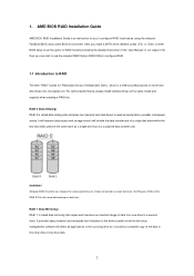
...pin DDR4 DIMM Slots (DDR4_A2, DDR4_B2) 5 AMD Fan LED Header (AMD_FAN_LED1) 6 RGB LED Header (RGB_HEADER1) 7 ATX Power Connector (ATXPWR1) 8 USB 3.1 Gen1 Header (USB3_5_6) 9 SATA3 Connector (SATA3_2) 10 SATA3 Connector (SATA3_1) 11 SATA3 Connector (SATA3_A1) 12 SATA3 Connector (SATA3_A2) 13 SATA3 Connector (SATA3_3) 14 SATA3 Connector (SATA3_4) 15 Power LED and Speaker Header (SPK_PLED1) 16 System Panel Header (PANEL1) 17 Chassis Fan Connector (CHA_FAN2) 18 Chassis Fan Connector (CHA_FAN1) 19 Clear CMOS Jumper (CLRCMOS1) 20 USB 2.0 Header (USB_3_4) 21 USB 2.0 Header (USB_1_2) 22 COM Port Header...
...pin DDR4 DIMM Slots (DDR4_A2, DDR4_B2) 5 AMD Fan LED Header (AMD_FAN_LED1) 6 RGB LED Header (RGB_HEADER1) 7 ATX Power Connector (ATXPWR1) 8 USB 3.1 Gen1 Header (USB3_5_6) 9 SATA3 Connector (SATA3_2) 10 SATA3 Connector (SATA3_1) 11 SATA3 Connector (SATA3_A1) 12 SATA3 Connector (SATA3_A2) 13 SATA3 Connector (SATA3_3) 14 SATA3 Connector (SATA3_4) 15 Power LED and Speaker Header (SPK_PLED1) 16 System Panel Header (PANEL1) 17 Chassis Fan Connector (CHA_FAN2) 18 Chassis Fan Connector (CHA_FAN1) 19 Clear CMOS Jumper (CLRCMOS1) 20 USB 2.0 Header (USB_3_4) 21 USB 2.0 Header (USB_1_2) 22 COM Port Header...
Quick Installation Guide
Page 7
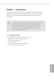
...to change without further notice. Because the motherboard specifications and the BIOS software might be updated, the content of this manual occur, the updated version will be subject to this manual will be available on ASRock's website as well. ASRock website http://www.asrock.com. 1.1 Package Contents • ASRock X370 Pro4 Motherboard (ATX Form Factor) • ASRock X370 Pro4 Quick Installation Guide • ASRock X370 Pro4 Support CD • 1 x I/O Panel Shield • 2 x Serial ATA (SATA) Data Cables (Optional) • 2 x Screws for purchasing ASRock X370 Pro4 motherboard...
...to change without further notice. Because the motherboard specifications and the BIOS software might be updated, the content of this manual occur, the updated version will be subject to this manual will be available on ASRock's website as well. ASRock website http://www.asrock.com. 1.1 Package Contents • ASRock X370 Pro4 Motherboard (ATX Form Factor) • ASRock X370 Pro4 Quick Installation Guide • ASRock X370 Pro4 Support CD • 1 x I/O Panel Shield • 2 x Serial ATA (SATA) Data Cables (Optional) • 2 x Screws for purchasing ASRock X370 Pro4 motherboard...
Quick Installation Guide
Page 10
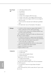
...) fan power. • 3 x Chassis Fan Connectors (4-pin) (Smart Fan Speed Control) * CHA_FAN2 and CHA_FAN3 can auto detect if 3-pin or 4-pin fan is occupied, PCIE4 will be disabled. • 1 x Ultra M.2 Socket (M2_1), supports type 2242/2260/2280 M.2 PCI Express module up to Gen3 x4 (32 Gb/s) (with Ryzen CPU) or Gen3 x2 (16 Gb/s) (with LED (ACT/LINK LED and SPEED LED) • HD Audio Jacks: Line in use. 8 English Rear Panel I/O • 1 x PS/2 Mouse/Keyboard Port • 1 x D-Sub Port •...
...) fan power. • 3 x Chassis Fan Connectors (4-pin) (Smart Fan Speed Control) * CHA_FAN2 and CHA_FAN3 can auto detect if 3-pin or 4-pin fan is occupied, PCIE4 will be disabled. • 1 x Ultra M.2 Socket (M2_1), supports type 2242/2260/2280 M.2 PCI Express module up to Gen3 x4 (32 Gb/s) (with Ryzen CPU) or Gen3 x2 (16 Gb/s) (with LED (ACT/LINK LED and SPEED LED) • HD Audio Jacks: Line in use. 8 English Rear Panel I/O • 1 x PS/2 Mouse/Keyboard Port • 1 x D-Sub Port •...
Quick Installation Guide
Page 11
... pin ATX Power Connector • 1 x 8 pin 12V Power Connector • 1 x Front Panel Audio Connector • 2 x USB 2.0 Headers (Support 4 USB 2.0 ports) (Supports ESD Protection) • 1 x USB 3.1 Gen1 Header (Supports 2 USB 3.1 Gen1 ports) (Supports ESD Protection) • AMI UEFI Legal BIOS with multilingual GUI support • Supports "Plug and Play" • ACPI 5.1 compliance wake up events • Supports jumperfree • SMBIOS 2.3 support • DRAM Voltage multi-adjustment • CPU/Chassis temperature sensing • CPU/Chassis Fan Tachometer • CPU/Chassis Quiet...
... pin ATX Power Connector • 1 x 8 pin 12V Power Connector • 1 x Front Panel Audio Connector • 2 x USB 2.0 Headers (Support 4 USB 2.0 ports) (Supports ESD Protection) • 1 x USB 3.1 Gen1 Header (Supports 2 USB 3.1 Gen1 ports) (Supports ESD Protection) • AMI UEFI Legal BIOS with multilingual GUI support • Supports "Plug and Play" • ACPI 5.1 compliance wake up events • Supports jumperfree • SMBIOS 2.3 support • DRAM Voltage multi-adjustment • CPU/Chassis temperature sensing • CPU/Chassis Fan Tachometer • CPU/Chassis Quiet...

Quick Installation Guide
Page 26
... sure that the power supply is switched off or the power cord is used for PCI Express x4 lane width graphics cards.** PCIE5 (PCIe 2.0 x1 slot) is occupied, PCIE4 will downgrade to x8 mode when A-Series APU is installed. ** PCIE4 will be disabled. 24 English PCIE4 (PCIe 3.0 x16 slot) is used for the card before you start the installation. 2.4 Expansion Slots (PCI Express Slots) There are 6 PCI Express slots on the motherboard. PCIe slots: PCIE1 (PCIe 2.0 x1 slot) is used for PCI Express x1 lane width...
... sure that the power supply is switched off or the power cord is used for PCI Express x4 lane width graphics cards.** PCIE5 (PCIe 2.0 x1 slot) is occupied, PCIE4 will downgrade to x8 mode when A-Series APU is installed. ** PCIE4 will be disabled. 24 English PCIE4 (PCIe 3.0 x16 slot) is used for the card before you start the installation. 2.4 Expansion Slots (PCI Express Slots) There are 6 PCI Express slots on the motherboard. PCIe slots: PCIE1 (PCIe 2.0 x1 slot) is used for PCI Express x1 lane width...
Quick Installation Guide
Page 29
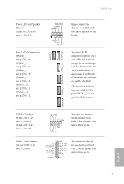
... connect the chassis power LED and the chassis speaker to 6.0 Gb/s data transfer rate. * M2_2 and SATA3_3 share lanes. If either one of them is one will be disabled. * To minimize the boot time, use , the other one header on this motherboard. Each USB 3.1 Gen1 header can support two ports. These six SATA3 connectors support SATA data cables for your bootable devices. SATA3_1 SATA3_4 SATA3_3 SATA3_A2 SATA3_A1 SATA3_2 English X370 Pro4 Power LED and Speaker Header (7-pin...
... connect the chassis power LED and the chassis speaker to 6.0 Gb/s data transfer rate. * M2_2 and SATA3_3 share lanes. If either one of them is one will be disabled. * To minimize the boot time, use , the other one header on this motherboard. Each USB 3.1 Gen1 header can support two ports. These six SATA3 connectors support SATA data cables for your bootable devices. SATA3_1 SATA3_4 SATA3_3 SATA3_A2 SATA3_A1 SATA3_2 English X370 Pro4 Power LED and Speaker Header (7-pin...
User Manual
Page 4
...I/O Panel 8 Chapter 2 Installation 10 2.1 Installing the CPU 11 2.2 Installing the CPU Fan and Heatsink 13 2.3 Installing Memory Modules (DIMM) 22 2.4 Expansion Slots (PCI Express Slots) 24 2.5 Jumpers Setup 25 2.6 Onboard Headers and Connectors 26 2.7 M.2_SSD (NGFF) Module Installation Guide (M2_1) 31 2.8 M.2_SSD (NGFF) Module Installation Guide (M2_2) 34 Chapter 3 Software and Utilities Operation 37 3.1 Installing Drivers 37 3.2 ASRock Live Update & APP Shop 38 3.2.1 UI Overview 38 3.2.2 Apps 39 3.2.3 BIOS & Drivers 42 3.2.4 Setting 43 3.3 ASRock RGB LED 44
...I/O Panel 8 Chapter 2 Installation 10 2.1 Installing the CPU 11 2.2 Installing the CPU Fan and Heatsink 13 2.3 Installing Memory Modules (DIMM) 22 2.4 Expansion Slots (PCI Express Slots) 24 2.5 Jumpers Setup 25 2.6 Onboard Headers and Connectors 26 2.7 M.2_SSD (NGFF) Module Installation Guide (M2_1) 31 2.8 M.2_SSD (NGFF) Module Installation Guide (M2_2) 34 Chapter 3 Software and Utilities Operation 37 3.1 Installing Drivers 37 3.2 ASRock Live Update & APP Shop 38 3.2.1 UI Overview 38 3.2.2 Apps 39 3.2.3 BIOS & Drivers 42 3.2.4 Setting 43 3.3 ASRock RGB LED 44
User Manual
Page 6
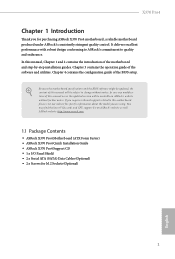
... Quick Installation Guide • ASRock X370 Pro4 Support CD • 1 x I/O Panel Shield • 2 x Serial ATA (SATA) Data Cables (Optional) • 2 x Screws for purchasing ASRock X370 Pro4 motherboard, a reliable motherboard produced under ASRock's consistently stringent quality control. X370 Pro4 Chapter 1 Introduction Thank you for M.2 Sockets (Optional) 1 English In this manual occur, the updated version will be available on ASRock's website as well. Chapter 4 contains the configuration guide of the software and utilities. Because the motherboard specifications and the BIOS...
... Quick Installation Guide • ASRock X370 Pro4 Support CD • 1 x I/O Panel Shield • 2 x Serial ATA (SATA) Data Cables (Optional) • 2 x Screws for purchasing ASRock X370 Pro4 motherboard, a reliable motherboard produced under ASRock's consistently stringent quality control. X370 Pro4 Chapter 1 Introduction Thank you for M.2 Sockets (Optional) 1 English In this manual occur, the updated version will be available on ASRock's website as well. Chapter 4 contains the configuration guide of the software and utilities. Because the motherboard specifications and the BIOS...

User Manual
Page 9
... M.2 PCI Express module up to 12V/3A, 36W LED Strip • 1 x AMD Fan LED Header • 1 x CPU Fan Connector (4-pin) * The CPU Fan Connector supports the CPU fan of them is in use, the other one will be disabled. ** Supports NVMe SSD as boot disks ** Supports ASRock U.2 Kit Connector • 1 x COM Port Header • 1 x TPM Header • 1 x Power LED and Speaker Header • 1 x RGB LED Header * Supports up to Gen3 x4 (32 Gb/s) (with Ryzen CPU) or Gen3 x2 (16 Gb/s) (with LED (ACT/LINK LED and SPEED LED) •...
... M.2 PCI Express module up to 12V/3A, 36W LED Strip • 1 x AMD Fan LED Header • 1 x CPU Fan Connector (4-pin) * The CPU Fan Connector supports the CPU fan of them is in use, the other one will be disabled. ** Supports NVMe SSD as boot disks ** Supports ASRock U.2 Kit Connector • 1 x COM Port Header • 1 x TPM Header • 1 x Power LED and Speaker Header • 1 x RGB LED Header * Supports up to Gen3 x4 (32 Gb/s) (with Ryzen CPU) or Gen3 x2 (16 Gb/s) (with LED (ACT/LINK LED and SPEED LED) •...

User Manual
Page 10
... pin ATX Power Connector • 1 x 8 pin 12V Power Connector • 1 x Front Panel Audio Connector • 2 x USB 2.0 Headers (Support 4 USB 2.0 ports) (Supports ESD Protection) • 1 x USB 3.1 Gen1 Header (Supports 2 USB 3.1 Gen1 ports) (Supports ESD Protection) • AMI UEFI Legal BIOS with multilingual GUI support • Supports "Plug and Play" • ACPI 5.1 compliance wake up events • Supports jumperfree • SMBIOS 2.3 support • DRAM Voltage multi-adjustment • CPU/Chassis temperature sensing • CPU/Chassis Fan Tachometer • CPU/Chassis Quiet...
... pin ATX Power Connector • 1 x 8 pin 12V Power Connector • 1 x Front Panel Audio Connector • 2 x USB 2.0 Headers (Support 4 USB 2.0 ports) (Supports ESD Protection) • 1 x USB 3.1 Gen1 Header (Supports 2 USB 3.1 Gen1 ports) (Supports ESD Protection) • AMI UEFI Legal BIOS with multilingual GUI support • Supports "Plug and Play" • ACPI 5.1 compliance wake up events • Supports jumperfree • SMBIOS 2.3 support • DRAM Voltage multi-adjustment • CPU/Chassis temperature sensing • CPU/Chassis Fan Tachometer • CPU/Chassis Quiet...

User Manual
Page 12
...pin DDR4 DIMM Slots (DDR4_A2, DDR4_B2) 5 AMD Fan LED Header (AMD_FAN_LED1) 6 RGB LED Header (RGB_HEADER1) 7 ATX Power Connector (ATXPWR1) 8 USB 3.1 Gen1 Header (USB3_5_6) 9 SATA3 Connector (SATA3_2) 10 SATA3 Connector (SATA3_1) 11 SATA3 Connector (SATA3_A1) 12 SATA3 Connector (SATA3_A2) 13 SATA3 Connector (SATA3_3) 14 SATA3 Connector (SATA3_4) 15 Power LED and Speaker Header (SPK_PLED1) 16 System Panel Header (PANEL1) 17 Chassis Fan Connector (CHA_FAN2) 18 Chassis Fan Connector (CHA_FAN1) 19 Clear CMOS Jumper (CLRCMOS1) 20 USB 2.0 Header (USB_3_4) 21 USB 2.0 Header (USB_1_2) 22 COM Port Header...
...pin DDR4 DIMM Slots (DDR4_A2, DDR4_B2) 5 AMD Fan LED Header (AMD_FAN_LED1) 6 RGB LED Header (RGB_HEADER1) 7 ATX Power Connector (ATXPWR1) 8 USB 3.1 Gen1 Header (USB3_5_6) 9 SATA3 Connector (SATA3_2) 10 SATA3 Connector (SATA3_1) 11 SATA3 Connector (SATA3_A1) 12 SATA3 Connector (SATA3_A2) 13 SATA3 Connector (SATA3_3) 14 SATA3 Connector (SATA3_4) 15 Power LED and Speaker Header (SPK_PLED1) 16 System Panel Header (PANEL1) 17 Chassis Fan Connector (CHA_FAN2) 18 Chassis Fan Connector (CHA_FAN1) 19 Clear CMOS Jumper (CLRCMOS1) 20 USB 2.0 Header (USB_3_4) 21 USB 2.0 Header (USB_1_2) 22 COM Port Header...

User Manual
Page 32
... There are two headers on this motherboard. Each USB 3.1 Gen1 header can support two ports. These six SATA3 connectors support SATA data cables for your bootable devices. If either one of them is one will be disabled. * To minimize the boot time, use , the other one header on this motherboard. SATA3_1 SATA3_4 SATA3_3 SATA3_A2 SATA3_A1 SATA3_2 English X370 Pro4 Power LED and Speaker Header (7-pin SPK_PLED1) (see p.6, No. 15) Serial ATA3 Connectors (SATA3_1: see p.6, No...
... There are two headers on this motherboard. Each USB 3.1 Gen1 header can support two ports. These six SATA3 connectors support SATA data cables for your bootable devices. If either one of them is one will be disabled. * To minimize the boot time, use , the other one header on this motherboard. SATA3_1 SATA3_4 SATA3_3 SATA3_A2 SATA3_A1 SATA3_2 English X370 Pro4 Power LED and Speaker Header (7-pin SPK_PLED1) (see p.6, No. 15) Serial ATA3 Connectors (SATA3_1: see p.6, No...
User Manual
Page 42
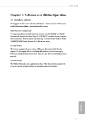
... the motherboard's features. Running The Support CD To begin using the support CD, insert the CD into your CD-ROM drive. X370 Pro4 Chapter 3 Software and Utilities Operation 3.1 Installing Drivers The Support CD that comes with the motherboard contains necessary drivers and useful utilities that the motherboard supports. If the Main Menu does not appear automatically, locate and double click on a specific item then follow the order from top to bottom to display the menu.
... the motherboard's features. Running The Support CD To begin using the support CD, insert the CD into your CD-ROM drive. X370 Pro4 Chapter 3 Software and Utilities Operation 3.1 Installing Drivers The Support CD that comes with the motherboard contains necessary drivers and useful utilities that the motherboard supports. If the Main Menu does not appear automatically, locate and double click on a specific item then follow the order from top to bottom to display the menu.

User Manual
Page 57
... Configuration options: [Enabled] and [Disabled]. Configuration options: [Enabled] and [Disabled]. Please set this item to [Enabled]. Please note that enabling this item to system stability or compatibility issue with some memory modules or power supplies. C6 Mode Use this function may reduce CPU voltage and memory frequency, and lead to enable or disable Core C6 mode. 4.4.1 CPU Configuration Cool 'n' Quiet Use this item to [Enabled], a VMM (Virtual Machine Architecture) can utilize the additional hardware capabilities provided by AMD-V. The default value is set to enable...
... Configuration options: [Enabled] and [Disabled]. Configuration options: [Enabled] and [Disabled]. Please set this item to [Enabled]. Please note that enabling this item to system stability or compatibility issue with some memory modules or power supplies. C6 Mode Use this function may reduce CPU voltage and memory frequency, and lead to enable or disable Core C6 mode. 4.4.1 CPU Configuration Cool 'n' Quiet Use this item to [Enabled], a VMM (Virtual Machine Architecture) can utilize the additional hardware capabilities provided by AMD-V. The default value is set to enable...

User Manual
Page 61
4.4.5 Super IO Configuration Serial Port Enable or disable the Serial port. Serial Port Address Select the address of the Serial port. PS2 Y-Cable Enable the PS2 Y-Cable or set this option to Auto. 56 English
4.4.5 Super IO Configuration Serial Port Enable or disable the Serial port. Serial Port Address Select the address of the Serial port. PS2 Y-Cable Enable the PS2 Y-Cable or set this option to Auto. 56 English

User Manual
Page 64
After copying the drivers please change the SATA mode to your liking. English 59 Easy RAID Installer Easy RAID Installer helps you to copy the RAID driver from the support CD to RAID, then you to adjust the RGB LED color to your USB storage device. 4.5 Tools X370 Pro4 RGB LED ASRock RGB LED allows you can start installing the operating system in RAID mode.
After copying the drivers please change the SATA mode to your liking. English 59 Easy RAID Installer Easy RAID Installer helps you to copy the RAID driver from the support CD to RAID, then you to adjust the RGB LED color to your USB storage device. 4.5 Tools X370 Pro4 RGB LED ASRock RGB LED allows you can start installing the operating system in RAID mode.
User Manual
Page 65
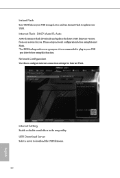
...Network Configuration Use this function. Please setup network configuration before using Internet Flash. *For BIOS backup and recovery purpose, it is recommended to plug in your UEFI. DHCP (Auto IP), Auto ASRock Internet Flash downloads and updates the latest UEFI firmware version from our servers for Internet Flash. Internet Flash - UEFI Download Server Select a server to download the UEFI firmware. 60 English Internet Setting Enable or disable sound effects in the setup utility. Instant Flash Save UEFI files in your USB storage device and run Instant Flash to update your USB...
...Network Configuration Use this function. Please setup network configuration before using Internet Flash. *For BIOS backup and recovery purpose, it is recommended to plug in your UEFI. DHCP (Auto IP), Auto ASRock Internet Flash downloads and updates the latest UEFI firmware version from our servers for Internet Flash. Internet Flash - UEFI Download Server Select a server to download the UEFI firmware. 60 English Internet Setting Enable or disable sound effects in the setup utility. Instant Flash Save UEFI files in your USB storage device and run Instant Flash to update your USB...


