
User Manual
Page 4
...1.2 Specifications 2 1.3 Motherboard Layout 6 1.4 Front Panel 9 1.5 Rear Panel 10 Chapter 2 Installation 11 2.1 Installing the CPU 12 2.2 Installing the CPU Fan and Heatsink 14 2.3 Installing Memory Modules (SO-DIMM) 19 2.4 Jumpers Setup 21 2.5 Onboard Headers and Connectors 22 2.6 M.2 WiFi/BT Module Installation Guide 25 2.7 M.2_SSD (NGFF) Module Installation Guide 27 Chapter 3 Software and Utilities Operation 29 3.1 Installing Drivers 29 Chapter 4 UEFI SETUP UTILITY 30 4.1 Introduction 30 4.1.1 UEFI Menu Bar 30 4.1.2 Navigation Keys 31 4.2 Main Screen 32...
...1.2 Specifications 2 1.3 Motherboard Layout 6 1.4 Front Panel 9 1.5 Rear Panel 10 Chapter 2 Installation 11 2.1 Installing the CPU 12 2.2 Installing the CPU Fan and Heatsink 14 2.3 Installing Memory Modules (SO-DIMM) 19 2.4 Jumpers Setup 21 2.5 Onboard Headers and Connectors 22 2.6 M.2 WiFi/BT Module Installation Guide 25 2.7 M.2_SSD (NGFF) Module Installation Guide 27 Chapter 3 Software and Utilities Operation 29 3.1 Installing Drivers 29 Chapter 4 UEFI SETUP UTILITY 30 4.1 Introduction 30 4.1.1 UEFI Menu Bar 30 4.1.2 Navigation Keys 31 4.2 Main Screen 32...
User Manual
Page 6
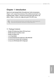
... • X300M-STX Motherboard (Mini-STX Form Factor) • X300M-STX Quick Installation Guide • X300M-STX Support CD • 1 x I/O Panel Shield • 2 x Serial ATA(SATA) Data with Power Cable (Optional) • 2 x Screws for M.2 Sockets (M2*2) (Optional) • 1 x Screw for purchasing X300M-STX motherboard. Because the motherboard specifications and the BIOS software might be updated, the content of the BIOS setup. Chapter 3 contains the operation guide of the motherboard and step-by-step installation guides. Chapter 4 contains the configuration guide of this...
... • X300M-STX Motherboard (Mini-STX Form Factor) • X300M-STX Quick Installation Guide • X300M-STX Support CD • 1 x I/O Panel Shield • 2 x Serial ATA(SATA) Data with Power Cable (Optional) • 2 x Screws for M.2 Sockets (M2*2) (Optional) • 1 x Screw for purchasing X300M-STX motherboard. Because the motherboard specifications and the BIOS software might be updated, the content of the BIOS setup. Chapter 3 contains the operation guide of the motherboard and step-by-step installation guides. Chapter 4 contains the configuration guide of this...

User Manual
Page 9
.../s) (with Raven Ridge) or Gen3 x2 (16 Gb/s) (with Athlon 2xxGE series)* * Supports NVMe SSD as boot disks Connector • 1 x Chassis Intrusion Header • 2 x CPU Fan Connectors (2 x 4-pin) • 1 x Front Panel Header • 1 x USB 2.0 Header (Supports 2 USB 2.0 ports) (Supports ESD Protection) • 1 x Audio Header • 1 x MONO Speaker Header BIOS Feature • AMI UEFI Legal BIOS with GUI support • Supports "Plug and Play" • ACPI 5.1 compliance wake up events • Supports jumperfree • SMBIOS 2.3 support • DRAM Voltage adjustment English 4
.../s) (with Raven Ridge) or Gen3 x2 (16 Gb/s) (with Athlon 2xxGE series)* * Supports NVMe SSD as boot disks Connector • 1 x Chassis Intrusion Header • 2 x CPU Fan Connectors (2 x 4-pin) • 1 x Front Panel Header • 1 x USB 2.0 Header (Supports 2 USB 2.0 ports) (Supports ESD Protection) • 1 x Audio Header • 1 x MONO Speaker Header BIOS Feature • AMI UEFI Legal BIOS with GUI support • Supports "Plug and Play" • ACPI 5.1 compliance wake up events • Supports jumperfree • SMBIOS 2.3 support • DRAM Voltage adjustment English 4
User Manual
Page 10
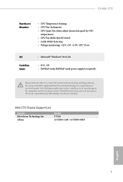
... risk involved with overclocking, including adjusting the setting in the BIOS, applying Untied Overclocking Technology, or using third-party overclocking tools. AKasa Model VT01S A-STX04-A1B / A-STX04-M1B English 5 Mini-STX Chassis Support List Vendor SilverStone Technology Inc. X300M-STX Hardware Monitor • CPU Temperature Sensing • CPU Fan Tachometer • CPU Quiet Fan (Auto adjust chassis fan speed by overclocking. Overclocking may affect your system's stability, or even cause damage to the components and devices of your own...
... risk involved with overclocking, including adjusting the setting in the BIOS, applying Untied Overclocking Technology, or using third-party overclocking tools. AKasa Model VT01S A-STX04-A1B / A-STX04-M1B English 5 Mini-STX Chassis Support List Vendor SilverStone Technology Inc. X300M-STX Hardware Monitor • CPU Temperature Sensing • CPU Fan Tachometer • CPU Quiet Fan (Auto adjust chassis fan speed by overclocking. Overclocking may affect your system's stability, or even cause damage to the components and devices of your own...
User Manual
Page 16
.... • When placing screws to secure the motherboard to the chassis, please do so may damage the motherboard. 11 English Failure to unplug the power cord before you install the motherboard, study the configuration of the following precautions before installing or removing the motherboard. Doing so may cause physical injuries to you uninstall any motherboard settings. • Make sure to do not overtighten...
.... • When placing screws to secure the motherboard to the chassis, please do so may damage the motherboard. 11 English Failure to unplug the power cord before you install the motherboard, study the configuration of the following precautions before installing or removing the motherboard. Doing so may cause physical injuries to you uninstall any motherboard settings. • Make sure to do not overtighten...

User Manual
Page 26
... BIOS option "Clear Status" to remove the jumper cap after clearing the CMOS. Please remember to clear the record of previous chassis intrusion status. X300M-STX 2.4 Jumpers Setup The illustration shows how jumpers are setup. If no jumper cap is placed on the pins, the jumper is "Short". To clear and reset the system parameters to default setup, please turn off the computer and unplug the power cord, then use a jumper cap to short the pins on the pins, the jumper...
... BIOS option "Clear Status" to remove the jumper cap after clearing the CMOS. Please remember to clear the record of previous chassis intrusion status. X300M-STX 2.4 Jumpers Setup The illustration shows how jumpers are setup. If no jumper cap is placed on the pins, the jumper is "Short". To clear and reset the system parameters to default setup, please turn off the computer and unplug the power cord, then use a jumper cap to short the pins on the pins, the jumper...

User Manual
Page 27
...+ Connect the power button, reset button and system status indicator on the chassis to this header, make sure the wire assignments and the pin assignments are NOT jumpers. You may differ by chassis. The LED keeps blinking when the system is reading or writing data. A front panel module mainly consists of power button, reset button, power LED, hard drive activity LED, speaker and etc. Placing jumper caps over these headers and connectors. The LED is on when the hard drive...
...+ Connect the power button, reset button and system status indicator on the chassis to this header, make sure the wire assignments and the pin assignments are NOT jumpers. You may differ by chassis. The LED keeps blinking when the system is reading or writing data. A front panel module mainly consists of power button, reset button, power LED, hard drive activity LED, speaker and etc. Placing jumper caps over these headers and connectors. The LED is on when the hard drive...
User Manual
Page 28
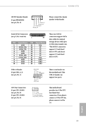
... SATA3 connectors support SATA data cables for internal storage devices with up to 6.0 Gb/s data transfer rate. *The SATA3 connectors support 2.5-inch hard drive (+5V) and do not support 3.5-inch hard drive (+12V) USB 2.0 Header (9-pin USB_4_5) (see p.6, No. 9) 4 3 21 GND FAN_VOLTAGE CPU_FAN_SPEED FAN_SPEED_CONTROL This motherboard provides two 4-Pin CPU fan (Quiet Fan) connectors. CPU Fan Connectors (4-pin CPU_FAN1) (see p.6, No. 8) (4-pin CPU_FAN2) (see p.6, No. 1) USB_PWR PP+ GND DUMMY 1 GND P+ PUSB_PWR There is one header on this header. X300M-STX MONO Speaker Header (4-pin...
... SATA3 connectors support SATA data cables for internal storage devices with up to 6.0 Gb/s data transfer rate. *The SATA3 connectors support 2.5-inch hard drive (+5V) and do not support 3.5-inch hard drive (+12V) USB 2.0 Header (9-pin USB_4_5) (see p.6, No. 9) 4 3 21 GND FAN_VOLTAGE CPU_FAN_SPEED FAN_SPEED_CONTROL This motherboard provides two 4-Pin CPU fan (Quiet Fan) connectors. CPU Fan Connectors (4-pin CPU_FAN1) (see p.6, No. 8) (4-pin CPU_FAN2) (see p.6, No. 1) USB_PWR PP+ GND DUMMY 1 GND P+ PUSB_PWR There is one header on this header. X300M-STX MONO Speaker Header (4-pin...

User Manual
Page 30
A Step 3 Gently insert the WiFi/BT module into the M.2 slot. A English A 20o 25 Please be used. The M.2 Socket (Key E) supports type 2230 WiFi/BT module. Installing the WiFi/BT module Step 1 Prepare a type 2230 WiFi/BT module and the screw. PCB Length: 3cm Module Type: Type2230 Step 2 Find the nut location to be aware that aims to replace mPCIe and mSATA. X300M-STX 2.6 M.2 WiFi/BT Module Installation Guide The M.2, also known as the Next Generation Form Factor (NGFF), is a small size and versatile card edge connector that the module only fits in one orientation.
A Step 3 Gently insert the WiFi/BT module into the M.2 slot. A English A 20o 25 Please be used. The M.2 Socket (Key E) supports type 2230 WiFi/BT module. Installing the WiFi/BT module Step 1 Prepare a type 2230 WiFi/BT module and the screw. PCB Length: 3cm Module Type: Type2230 Step 2 Find the nut location to be aware that aims to replace mPCIe and mSATA. X300M-STX 2.6 M.2 WiFi/BT Module Installation Guide The M.2, also known as the Next Generation Form Factor (NGFF), is a small size and versatile card edge connector that the module only fits in one orientation.

User Manual
Page 34
... install can work properly. Utilities Menu The Utilities Menu shows the application software that enhance the motherboard's features. X300M-STX Chapter 3 Software and Utilities Operation 3.1 Installing Drivers The Support CD that comes with the motherboard contains necessary drivers and useful utilities that the motherboard supports. Click on the support CD driver page. Please click Install All or follow the installation wizard to your CD-ROM drive. If the Main Menu does not appear automatically, locate and double click on the file...
... install can work properly. Utilities Menu The Utilities Menu shows the application software that enhance the motherboard's features. X300M-STX Chapter 3 Software and Utilities Operation 3.1 Installing Drivers The Support CD that comes with the motherboard contains necessary drivers and useful utilities that the motherboard supports. Click on the support CD driver page. Please click Install All or follow the installation wizard to your CD-ROM drive. If the Main Menu does not appear automatically, locate and double click on the file...

User Manual
Page 35
... reset button on . Because the UEFI software is constantly being updated, the following selections: Main For setting system time/date information OC Tweaker For overclocking configurations Advanced For advanced system configurations Tool Useful tools H/W Monitor Displays current hardware status Boot For configuring boot settings and boot priority Security For security settings Exit Exit the current screen or the UEFI Setup Utility English 30 Chapter 4 UEFI SETUP UTILITY 4.1 Introduction This section explains how to use the UEFI SETUP UTILITY to enter the UEFI SETUP UTILITY...
... reset button on . Because the UEFI software is constantly being updated, the following selections: Main For setting system time/date information OC Tweaker For overclocking configurations Advanced For advanced system configurations Tool Useful tools H/W Monitor Displays current hardware status Boot For configuring boot settings and boot priority Security For security settings Exit Exit the current screen or the UEFI Setup Utility English 30 Chapter 4 UEFI SETUP UTILITY 4.1 Introduction This section explains how to use the UEFI SETUP UTILITY to enter the UEFI SETUP UTILITY...
User Manual
Page 38
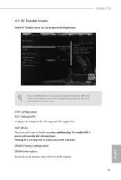
... be used to disable symmetric multithreading. 4.3 OC Tweaker Screen In the OC Tweaker screen, you see on systems where SMT is disabled. CPU Configuration SOC Voltage(VID) Configure the voltage for DDR4 modules. 33 English X300M-STX Because the UEFI software is needed after selecting [Auto]. SMT Mode This item can set up overclocking features. DRAM Timing Configuration DRAM Information Browse the serial presence defect (SPD) for the VID-requested SOC supply level...
... be used to disable symmetric multithreading. 4.3 OC Tweaker Screen In the OC Tweaker screen, you see on systems where SMT is disabled. CPU Configuration SOC Voltage(VID) Configure the voltage for DDR4 modules. 33 English X300M-STX Because the UEFI software is needed after selecting [Auto]. SMT Mode This item can set up overclocking features. DRAM Timing Configuration DRAM Information Browse the serial presence defect (SPD) for the VID-requested SOC supply level...

User Manual
Page 41
... options: [Enabled] and [Disabled]. Configuration options: [Enabled] and [Disabled]. 36 English AMD fTPM Switch Use this to enable or disable AMD's Cool 'n' QuietTM technology. The default value is [Enabled]. The default value is [Enabled]. 4.4.1 CPU Configuration Cool 'n' Quiet Use this item to enable or disable AMD CPU fTPM. SVM Mode When this option is set this function may reduce CPU voltage and memory frequency, and lead to [Disable] if above issue occurs. Please note that enabling this item to [Enabled], a VMM (Virtual Machine Architecture) can utilize...
... options: [Enabled] and [Disabled]. Configuration options: [Enabled] and [Disabled]. 36 English AMD fTPM Switch Use this to enable or disable AMD's Cool 'n' QuietTM technology. The default value is [Enabled]. The default value is [Enabled]. 4.4.1 CPU Configuration Cool 'n' Quiet Use this item to enable or disable AMD CPU fTPM. SVM Mode When this option is set this function may reduce CPU voltage and memory frequency, and lead to [Disable] if above issue occurs. Please note that enabling this item to [Enabled], a VMM (Virtual Machine Architecture) can utilize...

User Manual
Page 44
SATA Mode AHCI: Supports new features that improve performance. RAID: Combine multiple disk drives into a logical unit. 39 English 4.4.4 Storage Configuration X300M-STX SATA Controller(s) Enable/disable the SATA controllers.
SATA Mode AHCI: Supports new features that improve performance. RAID: Combine multiple disk drives into a logical unit. 39 English 4.4.4 Storage Configuration X300M-STX SATA Controller(s) Enable/disable the SATA controllers.

User Manual
Page 48
4.5 Tools X300M-STX Easy Driver Installer For users that don't have an optical disk drive to install the drivers from our support CD, Easy Driver Installer is a handy tool in your USB storage device and run Instant Flash to securely erase SSD. Instant Flash Save UEFI files in the UEFI that installs the LAN driver to your UEFI. 43 English SSD Secure Erase Tool Use this tool to update your system via an USB storage device, then downloads and installs the other required drivers automatically.
4.5 Tools X300M-STX Easy Driver Installer For users that don't have an optical disk drive to install the drivers from our support CD, Easy Driver Installer is a handy tool in your USB storage device and run Instant Flash to securely erase SSD. Instant Flash Save UEFI files in the UEFI that installs the LAN driver to your UEFI. 43 English SSD Secure Erase Tool Use this tool to update your system via an USB storage device, then downloads and installs the other required drivers automatically.
User Manual
Page 49
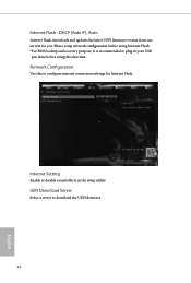
Please setup network configuration before using this to configure internet connection settings for you. UEFI Download Server Select a server to plug in the setup utility. Internet Setting Enable or disable sound effects in your USB pen drive before using Internet Flash. *For BIOS backup and recovery purpose, it is recommended to download the UEFI firmware. 44 English Network Configuration Use this function. Internet Flash - DHCP (Auto IP), Auto Internet Flash downloads and updates the latest UEFI firmware version from our servers for Internet Flash.
Please setup network configuration before using this to configure internet connection settings for you. UEFI Download Server Select a server to plug in the setup utility. Internet Setting Enable or disable sound effects in your USB pen drive before using Internet Flash. *For BIOS backup and recovery purpose, it is recommended to download the UEFI firmware. 44 English Network Configuration Use this function. Internet Flash - DHCP (Auto IP), Auto Internet Flash downloads and updates the latest UEFI firmware version from our servers for Internet Flash.
User Manual
Page 50
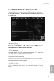
... down when the motherboard is overheated. Case Open Feature Enable or disable Case Open Feature to monitor the status of the hardware on your system, including the parameters of the CPU temperature, motherboard temperature, fan speed and voltage. CPU Fan 2 Setting Select a fan mode for CPU Fan 2, or choose Customize to set 5 CPU temperatures and assign a respective fan speed for each temperature. X300M-STX 4.6 Hardware Health Event Monitoring Screen This section allows you to detect whether the chassis cover has been...
... down when the motherboard is overheated. Case Open Feature Enable or disable Case Open Feature to monitor the status of the hardware on your system, including the parameters of the CPU temperature, motherboard temperature, fan speed and voltage. CPU Fan 2 Setting Select a fan mode for CPU Fan 2, or choose Customize to set 5 CPU temperatures and assign a respective fan speed for each temperature. X300M-STX 4.6 Hardware Health Event Monitoring Screen This section allows you to detect whether the chassis cover has been...

RAID Installation Guide
Page 2
... loss. Although RAID 0 function can start to use the onboard RAID Option ROM Utility to configure RAID. 1.1 Introduction to read and write data in parallel, interleaved stacks. RAID 0 (Data Striping) RAID 0 is called data mirroring that optimizes two identical hard disk drives to RAID The term "RAID" stands for you make a SATA driver diskette, press or to enter BIOS setup to set . It will improve data access and storage since the disk array management software will double...
... loss. Although RAID 0 function can start to use the onboard RAID Option ROM Utility to configure RAID. 1.1 Introduction to read and write data in parallel, interleaved stacks. RAID 0 (Data Striping) RAID 0 is called data mirroring that optimizes two identical hard disk drives to RAID The term "RAID" stands for you make a SATA driver diskette, press or to enter BIOS setup to set . It will improve data access and storage since the disk array management software will double...

RAID Installation Guide
Page 8
... a USB flash drive You can choose either STEP2.1 or STEP2.2 to Tools Easy RAID Installer F. C. Insert the Support CD into your USB flash disk. 8 A. E. Please download the "SATA Floppy Imaged driver" from ASRock's website A. Go to finish the configuration. Follow instructions to enter UEFI setup utility. Please install the DVD-ROM. B. Plug a USB drive into one of the USB port. K. During system boot, press or key to finish the driver copy process. D. STEP 2.2: Download driver from ASRock's website and unzip the file into the DVD-ROM drive...
... a USB flash drive You can choose either STEP2.1 or STEP2.2 to Tools Easy RAID Installer F. C. Insert the Support CD into your USB flash disk. 8 A. E. Please download the "SATA Floppy Imaged driver" from ASRock's website A. Go to finish the configuration. Follow instructions to enter UEFI setup utility. Please install the DVD-ROM. B. Plug a USB drive into one of the USB port. K. During system boot, press or key to finish the driver copy process. D. STEP 2.2: Download driver from ASRock's website and unzip the file into the DVD-ROM drive...

RAID Installation Guide
Page 9
... picture. Click to boot from AMD website. This is shown in this to find the driver inside your USB flash drive. B. While this point, then please open the boot menu that is the first. It should list the USB drive as a UEFI device. If the system restarts at this system is booting, please press F11 to open the F11 boot menu again. Using SATA/NVMe RAID driver package (version 9.2.0.127) from...
... picture. Click to boot from AMD website. This is shown in this to find the driver inside your USB flash drive. B. While this point, then please open the boot menu that is the first. It should list the USB drive as a UEFI device. If the system restarts at this system is booting, please press F11 to open the F11 boot menu again. Using SATA/NVMe RAID driver package (version 9.2.0.127) from...


