
User Manual
Page 5
... 49 2.13 M.2_SSD (NGFF) Module Installation Guide 50 Chapter 3 Software and Utilities Operation 54 3.1 Installing Drivers 54 3.2 Formula Drive 55 3.3 ASRock Live Update & APP Shop 58 3.3.1 UI Overview 58 3.3.2 Apps 59 3.3.3 BIOS & Drivers 62 3.3.4 Setting 63 3.4 ASRock RGB LED 64 Chapter 4 UEFI SETUP UTILITY 66 4.1 Introduction 66 4.2 EZ Mode 67 4.3 Advanced Mode 68 4.3.1 UEFI...
... 49 2.13 M.2_SSD (NGFF) Module Installation Guide 50 Chapter 3 Software and Utilities Operation 54 3.1 Installing Drivers 54 3.2 Formula Drive 55 3.3 ASRock Live Update & APP Shop 58 3.3.1 UI Overview 58 3.3.2 Apps 59 3.3.3 BIOS & Drivers 62 3.3.4 Setting 63 3.4 ASRock RGB LED 64 Chapter 4 UEFI SETUP UTILITY 66 4.1 Introduction 66 4.2 EZ Mode 67 4.3 Advanced Mode 68 4.3.1 UEFI...
User Manual
Page 7
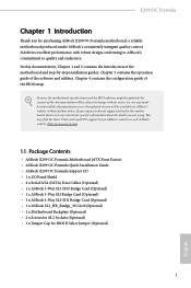
Chapter 3 contains the operation guide of the BIOS setup. X299 OC Formula Chapter 1 Introduction Thank you are using. Chapter 4 contains the configuration guide of the software and ...cards and CPU support list on ASRock's website without notice. In this documentation occur, the updated version will be available on ASRock's website as well. ASRock website http://www.asrock.com. 1.1 Package Contents • ASRock X299 OC Formula Motherboard (ATX Form Factor) • ASRock X299 OC Formula Quick Installation Guide • ASRock X299 OC Formula Support CD • 1 x...
Chapter 3 contains the operation guide of the BIOS setup. X299 OC Formula Chapter 1 Introduction Thank you are using. Chapter 4 contains the configuration guide of the software and ...cards and CPU support list on ASRock's website without notice. In this documentation occur, the updated version will be available on ASRock's website as well. ASRock website http://www.asrock.com. 1.1 Package Contents • ASRock X299 OC Formula Motherboard (ATX Form Factor) • ASRock X299 OC Formula Quick Installation Guide • ASRock X299 OC Formula Support CD • 1 x...

User Manual
Page 10
... supported on USB3_34 ports. • 4 x USB 3.1 Gen1 Ports (Supports ESD Protection) • 2 x RJ-45 LAN Ports with LED (ACT/LINK LED and SPEED LED) • 1 x BIOS Flashback Button • 1 x Clear CMOS Button • HD Audio Jacks: Rear Speaker / Central / Bass / Line in / Front Speaker / Microphone (Gold Audio Jacks) Storage • 6 x SATA3... M.2 SATA3 6.0 Gb/s module and M.2 PCI Express module up to Gen3 x4 (32 Gb/s)** ** Supports Intel® OptaneTM Technology ** Supports NVMe SSD as boot disks ** Supports ASRock U.2 Kit English 4
... supported on USB3_34 ports. • 4 x USB 3.1 Gen1 Ports (Supports ESD Protection) • 2 x RJ-45 LAN Ports with LED (ACT/LINK LED and SPEED LED) • 1 x BIOS Flashback Button • 1 x Clear CMOS Button • HD Audio Jacks: Rear Speaker / Central / Bass / Line in / Front Speaker / Microphone (Gold Audio Jacks) Storage • 6 x SATA3... M.2 SATA3 6.0 Gb/s module and M.2 PCI Express module up to Gen3 x4 (32 Gb/s)** ** Supports Intel® OptaneTM Technology ** Supports NVMe SSD as boot disks ** Supports ASRock U.2 Kit English 4

User Manual
Page 12
• 1 x Dr. Debug with LED • 1 x Power Button with multilingual GUI support (1 x Main BIOS and 1 x Backup BIOS) • Supports Secure Backup UEFI Technology • ACPI 6.1 Compliant wake up events • SMBIOS 3.0 Support • CPU, DRAM, VPPM, VTTM, PCH1.0, ...: CPU, CPU Optional/Water Pump, Chassis, Chassis Optional/Water Pump Fans • Quiet Fan (Auto adjust chassis fan speed by processor type. buttons to adjust OC frequency • 1 x Menu Button • 1 x PCIe ON/OFF Switch • 1 x Post Status Checker (PSC) • 1 x Slow Mode Switch • 1 x...
• 1 x Dr. Debug with LED • 1 x Power Button with multilingual GUI support (1 x Main BIOS and 1 x Backup BIOS) • Supports Secure Backup UEFI Technology • ACPI 6.1 Compliant wake up events • SMBIOS 3.0 Support • CPU, DRAM, VPPM, VTTM, PCH1.0, ...: CPU, CPU Optional/Water Pump, Chassis, Chassis Optional/Water Pump Fans • Quiet Fan (Auto adjust chassis fan speed by processor type. buttons to adjust OC frequency • 1 x Menu Button • 1 x PCIe ON/OFF Switch • 1 x Post Status Checker (PSC) • 1 x Slow Mode Switch • 1 x...
User Manual
Page 13
... done at your system. X299 OC Formula Certifications • FCC, CE • ErP/EuP ready (ErP/EuP ready power supply is required) * For detailed product information, please visit our website: http://www.asrock.com Please realize that there is a certain risk involved with overclocking, including adjusting the setting in the BIOS, applying Untied Overclocking Technology...
... done at your system. X299 OC Formula Certifications • FCC, CE • ErP/EuP ready (ErP/EuP ready power supply is required) * For detailed product information, please visit our website: http://www.asrock.com Please realize that there is a certain risk involved with overclocking, including adjusting the setting in the BIOS, applying Untied Overclocking Technology...

User Manual
Page 14
1.3 Motherboard Layout 1 2 3 4 56 7 8 9 CPU DRAM VGA BOOT USB 2.0 T: USB1 B: USB2 PS2 Keyboard /Mouse BIOS _FB1 CLRC BTN1 USB 3.1 Gen1 T: USB1 B: USB2 USB 3.1 Gen1 T: USB3 Top: B: USB4 RJ-45 USB 3.1 Gen2 T: USB31_TA_1 B:... PCIE4 23 1 24 M2_1 Ultra M.2 PCIe Gen3 x4 SATA3_0_1 Intel 25 X299 26 SATA3_2_3 SATA3_4_5 PCIE5 PCIE6 AUDIO CODEC PCIE7 HD_AUDIO1 1 HD_AUDIO_RA1 CLRMOS1 RGB_LED1 1 1 1 T B1 V_CTRL1 1 1 1 TPMS1 USB5_6 1 USB3_4 1 BIOS_B_LED1 BIOS_A_LED1 BIOS_B1 BIOS BIOS BIOS_A1 F_BIOS_B1 SPK_PLED1 1 1 Dr. Debug CHA_FAN3/ W_PUMP CHA_FAN1 PLED PWRBTN ...
1.3 Motherboard Layout 1 2 3 4 56 7 8 9 CPU DRAM VGA BOOT USB 2.0 T: USB1 B: USB2 PS2 Keyboard /Mouse BIOS _FB1 CLRC BTN1 USB 3.1 Gen1 T: USB1 B: USB2 USB 3.1 Gen1 T: USB3 Top: B: USB4 RJ-45 USB 3.1 Gen2 T: USB31_TA_1 B:... PCIE4 23 1 24 M2_1 Ultra M.2 PCIe Gen3 x4 SATA3_0_1 Intel 25 X299 26 SATA3_2_3 SATA3_4_5 PCIE5 PCIE6 AUDIO CODEC PCIE7 HD_AUDIO1 1 HD_AUDIO_RA1 CLRMOS1 RGB_LED1 1 1 1 T B1 V_CTRL1 1 1 1 TPMS1 USB5_6 1 USB3_4 1 BIOS_B_LED1 BIOS_A_LED1 BIOS_B1 BIOS BIOS BIOS_A1 F_BIOS_B1 SPK_PLED1 1 1 Dr. Debug CHA_FAN3/ W_PUMP CHA_FAN1 PLED PWRBTN ...

User Manual
Page 15
... DDR4_A1) 2 8 pin 12V Power Connector (ATX12V1) 3 4 pin 12V Power Connector (ATX12V2) 4 PCIe ON/OFF Switch (SWITCH1) 5 2 x 288-pin DDR4 DIMM Slots (DDR4_C1, DDR4_D1) 6 Rapid OC Button (+) (PLUS) 7 CPU Fan / Waterpump Fan Connector (CPU_OPT/W_PUMP) 8 CPU Fan Connector (CPU_FAN1) 9 Post Status Checker (PSC) 10 RGB LED Header (RGB_LED2) 11 Rapid...Fan Connector (CHA_FAN1) 29 System Panel Header (PANEL1) 30 Chassis Fan / Waterpump Fan Connector (CHA_FAN3/W_PUMP) 31 Power LED and Speaker Header (SPK_PLED1) 32 BIOS B Select Jumper (F_BIOS_B1) 33 USB 2.0 Header (USB3_4) 9 English X299 OC Formula No.
... DDR4_A1) 2 8 pin 12V Power Connector (ATX12V1) 3 4 pin 12V Power Connector (ATX12V2) 4 PCIe ON/OFF Switch (SWITCH1) 5 2 x 288-pin DDR4 DIMM Slots (DDR4_C1, DDR4_D1) 6 Rapid OC Button (+) (PLUS) 7 CPU Fan / Waterpump Fan Connector (CPU_OPT/W_PUMP) 8 CPU Fan Connector (CPU_FAN1) 9 Post Status Checker (PSC) 10 RGB LED Header (RGB_LED2) 11 Rapid...Fan Connector (CHA_FAN1) 29 System Panel Header (PANEL1) 30 Chassis Fan / Waterpump Fan Connector (CHA_FAN3/W_PUMP) 31 Power LED and Speaker Header (SPK_PLED1) 32 BIOS B Select Jumper (F_BIOS_B1) 33 USB 2.0 Header (USB3_4) 9 English X299 OC Formula No.

User Manual
Page 17
... 3.1 Gen2 Type-A Port (USB31_TA_1) 11 USB 3.1 Gen2 Type-C Port (USB31_TC_1) 12 USB 3.1 Gen1 Ports (USB3_34)*** 13 USB 3.1 Gen1 Ports (USB3_12) 14 Clear CMOS Button 15 BIOS Flashback Button 16 PS/2 Mouse/Keyboard Port (PS2_KB1) * There are two LEDs on each LAN port. Description 1 USB 2.0 Ports (USB12) 2 LAN RJ-45 Port (Intel... Speaker (Black) 6 Line In (Light Blue) 7 Front Speaker (Lime)** 8 Microphone (Pink) No. Please refer to the table below for the LAN port LED indications. 1.4 I/O Panel 1 X299 OC Formula 46 2 3 57 16 15 14 13 12 10 98 11 No.
... 3.1 Gen2 Type-A Port (USB31_TA_1) 11 USB 3.1 Gen2 Type-C Port (USB31_TC_1) 12 USB 3.1 Gen1 Ports (USB3_34)*** 13 USB 3.1 Gen1 Ports (USB3_12) 14 Clear CMOS Button 15 BIOS Flashback Button 16 PS/2 Mouse/Keyboard Port (PS2_KB1) * There are two LEDs on each LAN port. Description 1 USB 2.0 Ports (USB12) 2 LAN RJ-45 Port (Intel... Speaker (Black) 6 Line In (Light Blue) 7 Front Speaker (Lime)** 8 Microphone (Pink) No. Please refer to the table below for the LAN port LED indications. 1.4 I/O Panel 1 X299 OC Formula 46 2 3 57 16 15 14 13 12 10 98 11 No.

User Manual
Page 30
... the jumper cap is placed on CLRMOS1 for 5 seconds. If you need to clear the CMOS when you just finish updating the BIOS, you must boot up the system first, and then shut it down before you to clear the data in CMOS. English 24 After waiting for ...
... the jumper cap is placed on CLRMOS1 for 5 seconds. If you need to clear the CMOS when you just finish updating the BIOS, you must boot up the system first, and then shut it down before you to clear the data in CMOS. English 24 After waiting for ...

User Manual
Page 31
English 25 However, if the primary BIOS is corrupted or damaged, use a jumper cap to short the pins, then the backup BIOS will work on the next system boot. X299 OC Formula BIOS B Select Jumper (F_BIOS_B1) (see p.8, No. 32) 2-pin Jumper Short: Boot from BIOS B Open: Default This motherboard has two BIOS chips, a primary BIOS (BIOS_A1) and a backup BIOS (BIOS_B1), which enhances the safety and stability of your system. Normally, the system will take over on the primary BIOS.
English 25 However, if the primary BIOS is corrupted or damaged, use a jumper cap to short the pins, then the backup BIOS will work on the next system boot. X299 OC Formula BIOS B Select Jumper (F_BIOS_B1) (see p.8, No. 32) 2-pin Jumper Short: Boot from BIOS B Open: Default This motherboard has two BIOS chips, a primary BIOS (BIOS_A1) and a backup BIOS (BIOS_B1), which enhances the safety and stability of your system. Normally, the system will take over on the primary BIOS.

User Manual
Page 38
... motherboard has twelve smart switches: Power Button, Reset Button, Retry Button, Safe Boot Button, Clear CMOS Button, Rapid OC Buttons, Menu Button, PCIe ON/OFF Switch, Slow Mode Switch, LN2 Mode Switch and BIOS Flashback Button. Power Button (PWR) (see p.8 No. 16) If press this button, the next boot of the system...
... motherboard has twelve smart switches: Power Button, Reset Button, Retry Button, Safe Boot Button, Clear CMOS Button, Rapid OC Buttons, Menu Button, PCIe ON/OFF Switch, Slow Mode Switch, LN2 Mode Switch and BIOS Flashback Button. Power Button (PWR) (see p.8 No. 16) If press this button, the next boot of the system...

User Manual
Page 40
...BIOS Flashback is not installed; LN2 Mode Switch (LN2MODE1) (see p.11, No. 15) BIOS Flashback Button allows users to flash the BIOS. To use USB BIOS Flashback function, press the BIOS... Flashback Button for about three seconds. Rename the file to "creative.rom" and plug your USB flash drive must be FAT32. 3. Press the BIOS... Flashback Button for three seconds. USB BIOS Flashback port English 34 Wait until the LED stops blinking, indicating that BIOS... BIOS ...BIOS...
...BIOS Flashback is not installed; LN2 Mode Switch (LN2MODE1) (see p.11, No. 15) BIOS Flashback Button allows users to flash the BIOS. To use USB BIOS Flashback function, press the BIOS... Flashback Button for about three seconds. Rename the file to "creative.rom" and plug your USB flash drive must be FAT32. 3. Press the BIOS... Flashback Button for three seconds. USB BIOS Flashback port English 34 Wait until the LED stops blinking, indicating that BIOS... BIOS ...BIOS...

User Manual
Page 68
Please update them all soon. Click on Step 2 to see more items you will see a list of recommended or critical updates for the BIOS or drivers. Click to select one or more details. Step 1 Please check the item information before update. 3.3.3 BIOS & Drivers Installing BIOS or Drivers When the "BIOS & Drivers" tab is selected, you want to update. Step 3 Click Update to start the update process. 62 English
Please update them all soon. Click on Step 2 to see more items you will see a list of recommended or critical updates for the BIOS or drivers. Click to select one or more details. Step 1 Please check the item information before update. 3.3.3 BIOS & Drivers Installing BIOS or Drivers When the "BIOS & Drivers" tab is selected, you want to update. Step 3 Click Update to start the update process. 62 English

User Manual
Page 73
... screen to switch to Advanced Mode 67 English You can check the most crucial information of the system's current status. X299 OC Formula 4.2 EZ Mode The EZ Mode screen appears when you enter the BIOS setup program by default. EZ mode is a dashboard which contains multiple readings of your system, such as CPU speed...
... screen to switch to Advanced Mode 67 English You can check the most crucial information of the system's current status. X299 OC Formula 4.2 EZ Mode The EZ Mode screen appears when you enter the BIOS setup program by default. EZ mode is a dashboard which contains multiple readings of your system, such as CPU speed...

User Manual
Page 74
... following sections for the detailed configurations. 4.3 Advanced Mode The Advanced Mode provides more options to the following selections: Main For setting system time/date information OC Tweaker For overclocking configurations Advanced For advanced system configurations Tool Useful tools H/W Monitor Displays current hardware status Boot For configuring boot settings and boot priority...
... following sections for the detailed configurations. 4.3 Advanced Mode The Advanced Mode provides more options to the following selections: Main For setting system time/date information OC Tweaker For overclocking configurations Advanced For advanced system configurations Tool Useful tools H/W Monitor Displays current hardware status Boot For configuring boot settings and boot priority...

User Manual
Page 76
Favorite Display your collection of BIOS items. Press F5 to add/remove your favorite items. 70 English 4.4 Main Screen When you enter the UEFI SETUP UTILITY, the Main screen will appear and display the system overview.
Favorite Display your collection of BIOS items. Press F5 to add/remove your favorite items. 70 English 4.4 Main Screen When you enter the UEFI SETUP UTILITY, the Main screen will appear and display the system overview.

User Manual
Page 78
... the CPU Ratio multiplied with the BCLK. Flex Ratio Sets the value for ClockGen. Boot Performance Mode Select the performance state that the BIOS will increase the internal CPU clock speed but also affect the clock speed of other components. Increasing the BCLK will increase the internal CPU... clock speed but also affect the clock speed of other components. CPU Mesh Max Ratio Use this item to set the maximum OC Ratio for the CPU Mesh. Intel SpeedStep Technology Intel SpeedStep technology allows processors to run above its base operating frequency when the operating ...
... the CPU Ratio multiplied with the BCLK. Flex Ratio Sets the value for ClockGen. Boot Performance Mode Select the performance state that the BIOS will increase the internal CPU clock speed but also affect the clock speed of other components. Increasing the BCLK will increase the internal CPU... clock speed but also affect the clock speed of other components. CPU Mesh Max Ratio Use this item to set the maximum OC Ratio for the CPU Mesh. Intel SpeedStep Technology Intel SpeedStep technology allows processors to run above its base operating frequency when the operating ...

User Manual
Page 94
... for PCIE3. PCIE3 Link Speed Select the link speed for PCIE1. PCIE2 Link Speed Select the link speed for PCIE2. 4.6.2 Chipset Configuration Above 4GB MMIO BIOS Assignment Enable/disable above 4GB MemoryMappedIO BIOS assignment. This is disabled automatically when Aperture Size is set to 2048MB.
... for PCIE3. PCIE3 Link Speed Select the link speed for PCIE1. PCIE2 Link Speed Select the link speed for PCIE2. 4.6.2 Chipset Configuration Above 4GB MMIO BIOS Assignment Enable/disable above 4GB MemoryMappedIO BIOS assignment. This is disabled automatically when Aperture Size is set to 2048MB.
User Manual
Page 103
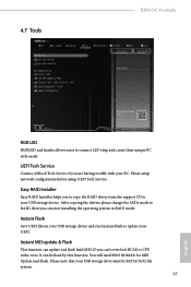
...ASRock Tech Service if you to copy the RAID driver from the support CD to RAID, then you can be FAT32/16/12 file system. 97 English Please setup network configuration before using UEFI Tech Service. After copying the drivers please change the SATA mode to your PC. You will need BIOS... ROM file for MEI Update and Flash. Instant Flash Save UEFI files in RAID mode. 4.7 Tools X299 OC Formula RGB LED RGB LED and header allows users to update your USB storage drive must be ...
...ASRock Tech Service if you to copy the RAID driver from the support CD to RAID, then you can be FAT32/16/12 file system. 97 English Please setup network configuration before using UEFI Tech Service. After copying the drivers please change the SATA mode to your PC. You will need BIOS... ROM file for MEI Update and Flash. Instant Flash Save UEFI files in RAID mode. 4.7 Tools X299 OC Formula RGB LED RGB LED and header allows users to update your USB storage drive must be ...
User Manual
Page 104
...function. Normally, the system will take over. Users may refer to the BIOS LEDs (BIOS_A_LED or BIOS_B_LED) to identify which enhances the safety and stability of your system. DHCP (Auto IP), Auto ASRock Internet Flash downloads and updates the latest UEFI firmware version from our servers ...for you. Use "Secure Backup UEFI" to duplicate a working ROM image to the secondary flash ROM. Internet Flash - However if the active BIOS is currently activated. 98 English...
...function. Normally, the system will take over. Users may refer to the BIOS LEDs (BIOS_A_LED or BIOS_B_LED) to identify which enhances the safety and stability of your system. DHCP (Auto IP), Auto ASRock Internet Flash downloads and updates the latest UEFI firmware version from our servers ...for you. Use "Secure Backup UEFI" to duplicate a working ROM image to the secondary flash ROM. Internet Flash - However if the active BIOS is currently activated. 98 English...


