
User Manual
Page 4
...1 1.2 Specifications 2 1.3 Motherboard Layout 8 1.4 I/O Panel 11 Chapter 2 Installation 13 2.1 Installing the CPU 14 2.2 Installing the CPU Fan and Heatsink 17 2.3 Installing the Motherboard Backplate 18 2.4 Installation of Memory Modules (DIMM) 20 2.5 Expansion Slots (PCI Express Slots) 22 2.6 Jumpers Setup 24 2.7 Onboard Headers and Connectors 26 2.8 Smart Switches 32 2.9 Dr. Debug 35 2.10 Post Status Checker 37 2.11 SLITM , 3-Way SLITM , 4-Way SLITM and Quad SLITM Operation Guide 38 2.11.1 Installing Two SLITM-Ready Graphics Cards 38 2.11.2 Installing Three...
...1 1.2 Specifications 2 1.3 Motherboard Layout 8 1.4 I/O Panel 11 Chapter 2 Installation 13 2.1 Installing the CPU 14 2.2 Installing the CPU Fan and Heatsink 17 2.3 Installing the Motherboard Backplate 18 2.4 Installation of Memory Modules (DIMM) 20 2.5 Expansion Slots (PCI Express Slots) 22 2.6 Jumpers Setup 24 2.7 Onboard Headers and Connectors 26 2.8 Smart Switches 32 2.9 Dr. Debug 35 2.10 Post Status Checker 37 2.11 SLITM , 3-Way SLITM , 4-Way SLITM and Quad SLITM Operation Guide 38 2.11.1 Installing Two SLITM-Ready Graphics Cards 38 2.11.2 Installing Three...
User Manual
Page 7
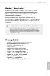
... the motherboard specifications and the BIOS software might be updated, the content of this documentation, Chapter 1 and 2 contains the introduction of the software and utilities. If you require technical support related to quality and endurance. In case any modifications of the BIOS setup. ASRock website http://www.asrock.com. 1.1 Package Contents • ASRock X299 OC Formula Motherboard (ATX Form Factor) • ASRock X299 OC Formula Quick Installation Guide • ASRock X299 OC Formula Support CD • 1 x I/O Panel Shield • 4 x Serial ATA (SATA) Data Cables (Optional...
... the motherboard specifications and the BIOS software might be updated, the content of this documentation, Chapter 1 and 2 contains the introduction of the software and utilities. If you require technical support related to quality and endurance. In case any modifications of the BIOS setup. ASRock website http://www.asrock.com. 1.1 Package Contents • ASRock X299 OC Formula Motherboard (ATX Form Factor) • ASRock X299 OC Formula Quick Installation Guide • ASRock X299 OC Formula Support CD • 1 x I/O Panel Shield • 4 x Serial ATA (SATA) Data Cables (Optional...
User Manual
Page 9
... SoundTM 4 - Individual PCB Layers for Front Panel Audio Connector (Supports up to 600 Ohm headsets) - Pure Power-In - PCB Isolate Shielding - Gold Audio Jacks - 15μ Gold Audio Connector • Supports DTS Connect • Gigabit LAN 10/100/1000 Mb/s • 1 x Giga PHY Intel® I219V, 1 x GigaLAN Intel® I211AT 3 English X299 OC Formula Audio LAN * Please note that the 3-Way SLITM configuration varies depending on Line Out port -
... SoundTM 4 - Individual PCB Layers for Front Panel Audio Connector (Supports up to 600 Ohm headsets) - Pure Power-In - PCB Isolate Shielding - Gold Audio Jacks - 15μ Gold Audio Connector • Supports DTS Connect • Gigabit LAN 10/100/1000 Mb/s • 1 x Giga PHY Intel® I219V, 1 x GigaLAN Intel® I211AT 3 English X299 OC Formula Audio LAN * Please note that the 3-Way SLITM configuration varies depending on Line Out port -

User Manual
Page 11
...X299 OC Formula Connector • 1 x Virtual RAID On CPU Header • 1 x TPM Header • 1 x Power LED and Speaker Header • 2 x RGB LED Headers * Supports in use. • 1 x 24 pin ATX Power Connector (Hi-Density Power Connector) (for Motherboard) • 1 x 8 pin 12V Power Connector (Hi-Density Power Connec- tor) (for Motherboard) • 1 x 4 pin 12V Power Connector (Hi-Density Power Connector) (for Motherboard) • 1 x 6 pin 12V Power Connector (Hi-Density Power Connector) (for PCIe graphics card) • 1 x Front Panel Audio Connector (15μ Gold Audio Connector...
...X299 OC Formula Connector • 1 x Virtual RAID On CPU Header • 1 x TPM Header • 1 x Power LED and Speaker Header • 2 x RGB LED Headers * Supports in use. • 1 x 24 pin ATX Power Connector (Hi-Density Power Connector) (for Motherboard) • 1 x 8 pin 12V Power Connector (Hi-Density Power Connec- tor) (for Motherboard) • 1 x 4 pin 12V Power Connector (Hi-Density Power Connector) (for Motherboard) • 1 x 6 pin 12V Power Connector (Hi-Density Power Connector) (for PCIe graphics card) • 1 x Front Panel Audio Connector (15μ Gold Audio Connector...

User Manual
Page 12
...; 1 x Safe Boot Button • Rapid OC Buttons: +/- • 1 x Dr. Debug with LED • 1 x Power Button with multilingual GUI support (1 x Main BIOS and 1 x Backup BIOS) • Supports Secure Backup UEFI Technology • ACPI 6.1 Compliant wake up events • SMBIOS 3.0 Support • CPU, DRAM, VPPM, VTTM, PCH1.0, CPU PLL, CPU PLL2, VCCIO, VCC PLL, CLK VDD Voltage Multi-adjustment * The supported voltage multi-adjustment may vary by CPU temperature): CPU, CPU Optional/Water Pump, Chassis, Chassis Optional/Water Pump Fans • Fan Multi-Speed Control: CPU, CPU Optional/Water...
...; 1 x Safe Boot Button • Rapid OC Buttons: +/- • 1 x Dr. Debug with LED • 1 x Power Button with multilingual GUI support (1 x Main BIOS and 1 x Backup BIOS) • Supports Secure Backup UEFI Technology • ACPI 6.1 Compliant wake up events • SMBIOS 3.0 Support • CPU, DRAM, VPPM, VTTM, PCH1.0, CPU PLL, CPU PLL2, VCCIO, VCC PLL, CLK VDD Voltage Multi-adjustment * The supported voltage multi-adjustment may vary by CPU temperature): CPU, CPU Optional/Water Pump, Chassis, Chassis Optional/Water Pump Fans • Fan Multi-Speed Control: CPU, CPU Optional/Water...

User Manual
Page 14
... M2_2 27 28 English 8 1.3 Motherboard Layout 1 2 3 4 56 7 8 9 CPU DRAM VGA BOOT USB 2.0 T: USB1 B: USB2 PS2 Keyboard /Mouse BIOS _FB1 CLRC BTN1 USB 3.1 Gen1 T: USB1 B: USB2 USB 3.1 Gen1 T: USB3 Top: B: USB4 RJ-45 USB 3.1 Gen2 T: USB31_TA_1 B: USB31_TC_1 Top: RJ-45 DDR4_B1 (64 bit, 288-pin module) DDR4_A1 (64 bit, 288-pin module) ATX12V1 ATX12V2 2066 Socket DDR4_C1 (64 bit, 288-pin module) DDR4_D1 (64 bit, 288-pin module) BFG_BTN1 RTY_BTN1 RSTBTN1 ON...
... M2_2 27 28 English 8 1.3 Motherboard Layout 1 2 3 4 56 7 8 9 CPU DRAM VGA BOOT USB 2.0 T: USB1 B: USB2 PS2 Keyboard /Mouse BIOS _FB1 CLRC BTN1 USB 3.1 Gen1 T: USB1 B: USB2 USB 3.1 Gen1 T: USB3 Top: B: USB4 RJ-45 USB 3.1 Gen2 T: USB31_TA_1 B: USB31_TC_1 Top: RJ-45 DDR4_B1 (64 bit, 288-pin module) DDR4_A1 (64 bit, 288-pin module) ATX12V1 ATX12V2 2066 Socket DDR4_C1 (64 bit, 288-pin module) DDR4_D1 (64 bit, 288-pin module) BFG_BTN1 RTY_BTN1 RSTBTN1 ON...

User Manual
Page 15
... 4 PCIe ON/OFF Switch (SWITCH1) 5 2 x 288-pin DDR4 DIMM Slots (DDR4_C1, DDR4_D1) 6 Rapid OC Button (+) (PLUS) 7 CPU Fan / Waterpump Fan Connector (CPU_OPT/W_PUMP) 8 CPU Fan Connector (CPU_FAN1) 9 Post Status Checker (PSC) 10 RGB LED Header (RGB_LED2) 11 Rapid OC Button (-) (MINUS) 12 Power Button (PWRBTN1) 13 Menu Button (MENU) 14 Reset Button (RSTBTN1) 15 Retry Button (RTY_BTN1) 16 Safe Boot Button (BFG_BTN1) 17 Slow Mode Switch (SLOWMODE) 18 LN2 Mode Switch (LN2MODE) 19 Virtual RAID On CPU Header (VROC1) 20 ATX Power Connector (ATXPWR1) 21 USB 3.1 Gen1 Header (USB3_5_6) 22 Graphics 12V Power...
... 4 PCIe ON/OFF Switch (SWITCH1) 5 2 x 288-pin DDR4 DIMM Slots (DDR4_C1, DDR4_D1) 6 Rapid OC Button (+) (PLUS) 7 CPU Fan / Waterpump Fan Connector (CPU_OPT/W_PUMP) 8 CPU Fan Connector (CPU_FAN1) 9 Post Status Checker (PSC) 10 RGB LED Header (RGB_LED2) 11 Rapid OC Button (-) (MINUS) 12 Power Button (PWRBTN1) 13 Menu Button (MENU) 14 Reset Button (RSTBTN1) 15 Retry Button (RTY_BTN1) 16 Safe Boot Button (BFG_BTN1) 17 Slow Mode Switch (SLOWMODE) 18 LN2 Mode Switch (LN2MODE) 19 Virtual RAID On CPU Header (VROC1) 20 ATX Power Connector (ATXPWR1) 21 USB 3.1 Gen1 Header (USB3_5_6) 22 Graphics 12V Power...

User Manual
Page 33
... is occupied by a SATA-type M.2 device, SATA3_5 will be disabled. English 27 X299 OC Formula Power LED and Speaker Header (7-pin SPK_PLED1) (see p.8, No. 23) SATA3_4 SATA3_2 SATA3_0 SATA3_A1 SATA3_5 SATA3_3 SATA3_1 SATA3_A2 These eight SATA3 connectors support SATA data cables for your bootable devices. * If M2_1 is occupied by a SATA-type M.2 device, SATA3_0 will be disabled. * If M2_2 is one header on this header. Each USB 2.0 header can support two ports. USB 3.1 Gen1 Header (19-pin USB3_5_6) (see p.8, No...
... is occupied by a SATA-type M.2 device, SATA3_5 will be disabled. English 27 X299 OC Formula Power LED and Speaker Header (7-pin SPK_PLED1) (see p.8, No. 23) SATA3_4 SATA3_2 SATA3_0 SATA3_A1 SATA3_5 SATA3_3 SATA3_1 SATA3_A2 These eight SATA3 connectors support SATA data cables for your bootable devices. * If M2_1 is occupied by a SATA-type M.2 device, SATA3_0 will be disabled. * If M2_2 is one header on this header. Each USB 2.0 header can support two ports. USB 3.1 Gen1 Header (19-pin USB3_5_6) (see p.8, No...

User Manual
Page 34
... is one of the audio connectors. 1. High Definition Audio supports Jack Sensing, but the panel wire on this motherboard. MIC_RET and OUT_RET are for additional USB 3.1 Gen2 ports. This header is used for connecting a USB 3.1 Gen2 module for the HD audio panel only. D. Connect Audio_R (RIN) to OUT2_R and Audio_L (LIN) to either one Front Panel Type C USB 3.1 Gen2 Header on the chassis must support HDA to the ground pin. (4-pin CHA_FAN2) (see p.8, No. 42...
... is one of the audio connectors. 1. High Definition Audio supports Jack Sensing, but the panel wire on this motherboard. MIC_RET and OUT_RET are for additional USB 3.1 Gen2 ports. This header is used for connecting a USB 3.1 Gen2 module for the HD audio panel only. D. Connect Audio_R (RIN) to OUT2_R and Audio_L (LIN) to either one Front Panel Type C USB 3.1 Gen2 Header on the chassis must support HDA to the ground pin. (4-pin CHA_FAN2) (see p.8, No. 42...

User Manual
Page 36
... store keys, digital certificates, passwords, and data. A TPM system also helps enhance network security, protects digital identities, and ensures platform integrity. Voltage Control Header (5-pin V_CTRL1) (see p.8, No. 37) PCICLK FRAM E PCIRST # LAD3 +3V LAD0 +3VS B GN D GN D SMB_CLK_MAIN SMB_DATA_MAIN LAD2 LAD1 GN D S_PWRDWN # SERIRQ # GND Please connect an ATX 12V power supply to this connector via the GPIO cable. This motherboard provides a 6-pin Graphics 12V power connector. * Install...
... store keys, digital certificates, passwords, and data. A TPM system also helps enhance network security, protects digital identities, and ensures platform integrity. Voltage Control Header (5-pin V_CTRL1) (see p.8, No. 37) PCICLK FRAM E PCIRST # LAD3 +3V LAD0 +3VS B GN D GN D SMB_CLK_MAIN SMB_DATA_MAIN LAD2 LAD1 GN D S_PWRDWN # SERIRQ # GND Please connect an ATX 12V power supply to this connector via the GPIO cable. This motherboard provides a 6-pin Graphics 12V power connector. * Install...

User Manual
Page 40
... LN2 mode aids in eliminating the cold-boot bug issues in processors during extreme overclocking with Liquid Nitrogen. USB BIOS Flashback port English 34 Make sure that the BIOS Flashback is not installed; Then the LED starts to blink. 7. To use USB BIOS Flashback function, press the BIOS Flashback Button for about three seconds. Rename the file to "creative.rom" and plug your USB flash drive must be FAT32. 3. then install PSU and turn...
... LN2 mode aids in eliminating the cold-boot bug issues in processors during extreme overclocking with Liquid Nitrogen. USB BIOS Flashback port English 34 Make sure that the BIOS Flashback is not installed; Then the LED starts to blink. 7. To use USB BIOS Flashback function, press the BIOS Flashback Button for about three seconds. Rename the file to "creative.rom" and plug your USB flash drive must be FAT32. 3. then install PSU and turn...

User Manual
Page 41
...-install the CPU and memory then clear CMOS. b0 Problem related to PCI-E devices. X299 OC Formula 2.9 Dr. Debug Dr. Debug is installed correctly and then clear CMOS. 0d Problem related to memory, VGA card or other devices. A0 - Please see the diagrams below for reading the Dr. Debug codes. If the problem still exists, please install only one memory module or try using other memory modules. 55 The Memory could not be detected. Please press reset or clear CMOS...
...-install the CPU and memory then clear CMOS. b0 Problem related to PCI-E devices. X299 OC Formula 2.9 Dr. Debug Dr. Debug is installed correctly and then clear CMOS. 0d Problem related to memory, VGA card or other devices. A0 - Please see the diagrams below for reading the Dr. Debug codes. If the problem still exists, please install only one memory module or try using other memory modules. 55 The Memory could not be detected. Please press reset or clear CMOS...
User Manual
Page 51
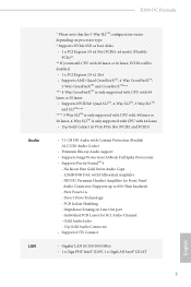
... to AMD graphics card manuals for detailed installation guide. 2.12.1 Installing Two CrossFireXTM-Ready Graphics Cards Step 1 Insert one graphics card into PCIE1 slot and the other graphics card to your graphics card vendor for details. 4. Make sure that your system requires. Please refer to PCIE5 slot. You should only use a AMD certified PSU. Make sure that your power supply unit (PSU) can provide at least the minimum power your graphics card driver supports AMD CrossFireXTM technology. X299 OC Formula 2.12...
... to AMD graphics card manuals for detailed installation guide. 2.12.1 Installing Two CrossFireXTM-Ready Graphics Cards Step 1 Insert one graphics card into PCIE1 slot and the other graphics card to your graphics card vendor for details. 4. Make sure that your system requires. Please refer to PCIE5 slot. You should only use a AMD certified PSU. Make sure that your power supply unit (PSU) can provide at least the minimum power your graphics card driver supports AMD CrossFireXTM technology. X299 OC Formula 2.12...

User Manual
Page 55
... the GPU number according to installation. English 49 Step 2 Remove the AMD drivers if you have any previously installed Catalyst drivers prior to your computer and boot into OS. Please check AMD's website for details. Then select Enable AMD CrossFireX and click Apply. Please check AMD's website for AMD driver updates. X299 OC Formula 2.12.4 Driver Installation and Setup Step 1 Power on your graphics card and click Apply. The Catalyst Uninstaller is an optional download.
... the GPU number according to installation. English 49 Step 2 Remove the AMD drivers if you have any previously installed Catalyst drivers prior to your computer and boot into OS. Please check AMD's website for details. Then select Enable AMD CrossFireX and click Apply. Please check AMD's website for AMD driver updates. X299 OC Formula 2.12.4 Driver Installation and Setup Step 1 Power on your graphics card and click Apply. The Catalyst Uninstaller is an optional download.
User Manual
Page 60
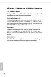
... automatically displays the Main Menu if "AUTORUN" is enabled in the Support CD to display the menu. Drivers Menu The drivers compatible to your CD-ROM drive. Therefore, the drivers you install can work properly. Please click Install All or follow the installation wizard to install those required drivers. Click on the support CD driver page. Chapter 3 Software and Utilities Operation 3.1 Installing Drivers The Support CD that comes with the motherboard contains necessary drivers and useful utilities that the motherboard supports. Utilities Menu The Utilities Menu shows...
... automatically displays the Main Menu if "AUTORUN" is enabled in the Support CD to display the menu. Drivers Menu The drivers compatible to your CD-ROM drive. Therefore, the drivers you install can work properly. Please click Install All or follow the installation wizard to install those required drivers. Click on the support CD driver page. Chapter 3 Software and Utilities Operation 3.1 Installing Drivers The Support CD that comes with the motherboard contains necessary drivers and useful utilities that the motherboard supports. Utilities Menu The Utilities Menu shows...

User Manual
Page 95
... PCIE devices. Onboard Debug Port LED Enable/disable the onboard Dr. Debug LED. Inte(R) Ethernet Connection I211AT Enable or disable the onboard network interface controller (Intel® I211AT). If [Power On] is installed. Turn On LED in the ACPI S5 state. 89 English PCH DMI ASPM Support This option enables/disables the ASPM support for PCIE6. Onboard HD Audio Enable/disable onboard HD audio. PCIE6 Link Speed Select the link speed for all PCH DMI devices. If [Power Off] is selected, the power will start to enable onboard HD audio...
... PCIE devices. Onboard Debug Port LED Enable/disable the onboard Dr. Debug LED. Inte(R) Ethernet Connection I211AT Enable or disable the onboard network interface controller (Intel® I211AT). If [Power On] is installed. Turn On LED in the ACPI S5 state. 89 English PCH DMI ASPM Support This option enables/disables the ASPM support for PCIE6. Onboard HD Audio Enable/disable onboard HD audio. PCIE6 Link Speed Select the link speed for all PCH DMI devices. If [Power Off] is selected, the power will start to enable onboard HD audio...
User Manual
Page 103
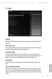
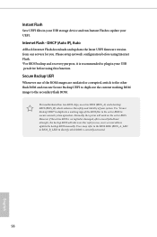
Please setup network configuration before using UEFI Tech Service. Instant MEI update & Flash This function can 't overclock BCLK or CPU turbo ratio. If you are having trouble with your PC. You will need BIOS ROM file for MEI Update and Flash. Please note that your USB storage drive must be fixed by this function. After copying the drivers please change the SATA mode to update your UEFI. Instant Flash Save UEFI files in RAID mode. It can start installing the operating system in...
Please setup network configuration before using UEFI Tech Service. Instant MEI update & Flash This function can 't overclock BCLK or CPU turbo ratio. If you are having trouble with your PC. You will need BIOS ROM file for MEI Update and Flash. Please note that your USB storage drive must be fixed by this function. After copying the drivers please change the SATA mode to update your UEFI. Instant Flash Save UEFI files in RAID mode. It can start installing the operating system in...
User Manual
Page 104
... working copy of your USB pen drive before using this function. For safety issues, users are outdated or corrupted, switch to the other flash ROM and execute Secure Backup UEFI to the secondary flash ROM. Users may refer to the BIOS LEDs (BIOS_A_LED or BIOS_B_LED) to identify which enhances the safety and stability of the BIOS files to the active BIOS to update your UEFI. Please setup network configuration before using Internet Flash. *For BIOS...
... working copy of your USB pen drive before using this function. For safety issues, users are outdated or corrupted, switch to the other flash ROM and execute Secure Backup UEFI to the secondary flash ROM. Users may refer to the BIOS LEDs (BIOS_A_LED or BIOS_B_LED) to identify which enhances the safety and stability of the BIOS files to the active BIOS to update your UEFI. Please setup network configuration before using Internet Flash. *For BIOS...

User Manual
Page 105
Internet Setting Enable or disable sound effects in the setup utility. UEFI Download Server Select a server to configure internet connection settings for Internet Flash. X299 OC Formula Network Configuration Use this to download the UEFI firmware. 99 English
Internet Setting Enable or disable sound effects in the setup utility. UEFI Download Server Select a server to configure internet connection settings for Internet Flash. X299 OC Formula Network Configuration Use this to download the UEFI firmware. 99 English

User Manual
Page 109
.../user password for Windows 8.1 Secure Boot. Disable this option to enable or disable support for the system. Secure Boot Use this item to use discrete TPM Module. 103 English User Password Set or change the password for the user account. You may set or change the settings in ME. Supervisor Password Set or change the password for the administrator account. Leave it blank and press enter to remove the password. Leave it blank and press enter to remove the password. X299 OC Formula 4.9 Security Screen...
.../user password for Windows 8.1 Secure Boot. Disable this option to enable or disable support for the system. Secure Boot Use this item to use discrete TPM Module. 103 English User Password Set or change the password for the user account. You may set or change the settings in ME. Supervisor Password Set or change the password for the administrator account. Leave it blank and press enter to remove the password. Leave it blank and press enter to remove the password. X299 OC Formula 4.9 Security Screen...


