
Intel Rapid Storage Guide
Page 1
... faster boot times and data reads. When the failed drive is removed and a replacement hard drive is installed, data fault tolerance is improved through Native Command Queuing (NCQ). Also, due to drive load balancing, even systems with an external drive. When using one or multiple hard drives, users can be accomplished easily with RAID 1 can reduce the power consumption of the chipset and Serial ATA (SATA) hard drive. 1 Starting with Link Power Management...
... faster boot times and data reads. When the failed drive is removed and a replacement hard drive is installed, data fault tolerance is improved through Native Command Queuing (NCQ). Also, due to drive load balancing, even systems with an external drive. When using one or multiple hard drives, users can be accomplished easily with RAID 1 can reduce the power consumption of the chipset and Serial ATA (SATA) hard drive. 1 Starting with Link Power Management...

Intel Rapid Storage Guide
Page 12
Enable RAID in System BIOS Use the instructions included with your motherboard to enable RAID in the system BIOS, a RAID volume must be created, and the F6 installation method must be enabled in the system BIOS. 1. Click the Storage Configuration menu. 4. When the Intel Rapid Storage Technology option ROM status screen appears during operating system setup. Unless you have selected RAID 1, use the up or down arrow keys to scroll through the list of hard drives by using the up...
Enable RAID in System BIOS Use the instructions included with your motherboard to enable RAID in the system BIOS, a RAID volume must be created, and the F6 installation method must be enabled in the system BIOS. 1. Click the Storage Configuration menu. 4. When the Intel Rapid Storage Technology option ROM status screen appears during operating system setup. Unless you have selected RAID 1, use the up or down arrow keys to scroll through the list of hard drives by using the up...
Intel Rapid Storage Guide
Page 13
... visible. 6. Use the up and down arrow keys to install the Intel Rapid Storage Technology driver during text-mode phase). You will temporarily continue loading drivers. At the prompt press Y to Specify Additional Device. 3. Select your controller and continue. At this point, you see a message in the status line that says, Please insert the disk labeled Manufacturer-supplied hardware support disk into Drive A:, insert ;a floppy disk containing the...
... visible. 6. Use the up and down arrow keys to install the Intel Rapid Storage Technology driver during text-mode phase). You will temporarily continue loading drivers. At the prompt press Y to Specify Additional Device. 3. Select your controller and continue. At this point, you see a message in the status line that says, Please insert the disk labeled Manufacturer-supplied hardware support disk into Drive A:, insert ;a floppy disk containing the...

Intel Rapid Storage Guide
Page 16
... be used to load the Intel® Rapid Storage Technology driver during operating system installation. Note If you do not need to install a third party SCSI or RAID driver. You can use the F6 installation method to install a RAID Note driver on your system, you can use the Floppy Configuration Utility to create a floppy disk with a screen asking you need to use a USB floppy drive or create a slipstream version of Windows setup (during text-mode phase). Use the following files: IAAHCI...
... be used to load the Intel® Rapid Storage Technology driver during operating system installation. Note If you do not need to install a third party SCSI or RAID driver. You can use the F6 installation method to install a RAID Note driver on your system, you can use the Floppy Configuration Utility to create a floppy disk with a screen asking you need to use a USB floppy drive or create a slipstream version of Windows setup (during text-mode phase). Use the following files: IAAHCI...

RAID Installation Guide
Page 1
...to SATA Hard Disks Installation 2 1.1 Serial ATA (SATA) Hard Disks Installation 2 2. Guide to RAID Configurations 3 2.1 Introduction of RAID 3 2.2 RAID Configuration Precautions 6 2.3 Installing Windows® 10 64-bit With RAID Functions..7 2.4 Configuring a RAID array 8 2.4.1 Configuring a RAID array Using UEFI Setup Utility....... 9 2.4.2 Configuring a PCIE SSD RAID Array Using UEFI Setup Utility 13 2.4.3 Configuring a RAID array Using Intel RAID BIOS....... 18 3. Installing Windows® on a HDD larger than 2TB in RAID mode 22 4. Guide to SATA Hard Disks Installation and...
...to SATA Hard Disks Installation 2 1.1 Serial ATA (SATA) Hard Disks Installation 2 2. Guide to RAID Configurations 3 2.1 Introduction of RAID 3 2.2 RAID Configuration Precautions 6 2.3 Installing Windows® 10 64-bit With RAID Functions..7 2.4 Configuring a RAID array 8 2.4.1 Configuring a RAID array Using UEFI Setup Utility....... 9 2.4.2 Configuring a PCIE SSD RAID Array Using UEFI Setup Utility 13 2.4.3 Configuring a RAID array Using Intel RAID BIOS....... 18 3. Installing Windows® on a HDD larger than 2TB in RAID mode 22 4. Guide to SATA Hard Disks Installation and...

RAID Installation Guide
Page 7
... models A. STEP 4: Install Windows® 10 64-bit OS on your USB storage device with RAID functions, please follow the procedures below. Enter UEFI SETUP UTILITY Tool and highlight "Easy RAID Installer". STEP 3: Set RAID configuration Please refer to p.8 -17 of this feature is not available for instructions on how to install Windows® 10 64-bit OS on your RAID configuration. Go to Advanced Storage Configuration and set SATA Mode Selection to enter BIOS setup utility. Boot your USB flash drive into a USB port B. Plug in the BIOS before setting...
... models A. STEP 4: Install Windows® 10 64-bit OS on your USB storage device with RAID functions, please follow the procedures below. Enter UEFI SETUP UTILITY Tool and highlight "Easy RAID Installer". STEP 3: Set RAID configuration Please refer to p.8 -17 of this feature is not available for instructions on how to install Windows® 10 64-bit OS on your RAID configuration. Go to Advanced Storage Configuration and set SATA Mode Selection to enter BIOS setup utility. Boot your USB flash drive into a USB port B. Plug in the BIOS before setting...

RAID Installation Guide
Page 23
... Intel® RAID drivers into a USB flash disk You can download the drivers from ASRock's website and unzip the files into a USB flash disk or copy the files from ASRock's motherboard support CD. (Please copy the files under the following directory: 32 bit: ..\i386\Win7_Intel.. 64-bit: ..\AMD64\Win7-64_Intel.. Installing Windows® on a HDD larger than 2TB in RAID mode Windows® 10 does not support HDD's larger than 2TB. After the UEFI and RAID BIOS setup, please follow the...
... Intel® RAID drivers into a USB flash disk You can download the drivers from ASRock's website and unzip the files into a USB flash disk or copy the files from ASRock's motherboard support CD. (Please copy the files under the following directory: 32 bit: ..\i386\Win7_Intel.. 64-bit: ..\AMD64\Win7-64_Intel.. Installing Windows® on a HDD larger than 2TB in RAID mode Windows® 10 does not support HDD's larger than 2TB. After the UEFI and RAID BIOS setup, please follow the...

RAID Installation Guide
Page 25
... need to follow the instructions below to fix this problem. E. If you will install this hotfix then reboot by itself. If you encounter this link: http://support.microsoft.com/kb/2505454/ B. Please start to boot into Windows® or install driver/utilities. After installing Windows® 10 64-bit, install the hotfix kb2505454. (This may take more time to install motherboard drivers and utilities. 25 Disk volume > 2TB), it...
... need to follow the instructions below to fix this problem. E. If you will install this hotfix then reboot by itself. If you encounter this link: http://support.microsoft.com/kb/2505454/ B. Please start to boot into Windows® or install driver/utilities. After installing Windows® 10 64-bit, install the hotfix kb2505454. (This may take more time to install motherboard drivers and utilities. 25 Disk volume > 2TB), it...

User Manual
Page 4
...1.2 Specifications 2 1.3 Motherboard Layout 7 1.4 I/O Panel 9 Chapter 2 Installation 11 2.1 Installing the CPU 12 2.2 Installing the CPU Fan and Heatsink 15 2.3 Installation of Memory Modules (DIMM) 16 2.4 Expansion Slots (PCI Express Slots) 18 2.5 Jumpers Setup 20 2.6 Onboard Headers and Connectors 21 2.7 Smart Switch 27 2.8 SLITM and Quad SLITM Operation Guide 28 2.8.1 Installing Two SLITM-Ready Graphics Cards 28 2.8.2 Driver Installation and Setup 30 2.9 CrossFireXTM and Quad CrossFireXTM Operation Guide 31 2.9.1 Installing Two CrossFireXTM-Ready Graphics Cards...
...1.2 Specifications 2 1.3 Motherboard Layout 7 1.4 I/O Panel 9 Chapter 2 Installation 11 2.1 Installing the CPU 12 2.2 Installing the CPU Fan and Heatsink 15 2.3 Installation of Memory Modules (DIMM) 16 2.4 Expansion Slots (PCI Express Slots) 18 2.5 Jumpers Setup 20 2.6 Onboard Headers and Connectors 21 2.7 Smart Switch 27 2.8 SLITM and Quad SLITM Operation Guide 28 2.8.1 Installing Two SLITM-Ready Graphics Cards 28 2.8.2 Driver Installation and Setup 30 2.9 CrossFireXTM and Quad CrossFireXTM Operation Guide 31 2.9.1 Installing Two CrossFireXTM-Ready Graphics Cards...
User Manual
Page 7
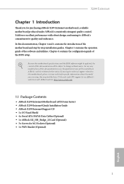
... the configuration guide of this documentation occur, the updated version will be available on ASRock's website as well. You may find the latest VGA cards and CPU support list on ASRock's website without notice. If you require technical support related to change without further notice. ASRock website http://www.asrock.com. 1.1 Package Contents • ASRock X299 Extreme4 Motherboard (ATX Form Factor) • ASRock X299 Extreme4 Quick Installation Guide • ASRock X299 Extreme4 Support CD • 1 x I/O Panel Shield • 4 x Serial ATA (SATA) Data Cables (Optional...
... the configuration guide of this documentation occur, the updated version will be available on ASRock's website as well. You may find the latest VGA cards and CPU support list on ASRock's website without notice. If you require technical support related to change without further notice. ASRock website http://www.asrock.com. 1.1 Package Contents • ASRock X299 Extreme4 Motherboard (ATX Form Factor) • ASRock X299 Extreme4 Quick Installation Guide • ASRock X299 Extreme4 Support CD • 1 x I/O Panel Shield • 4 x Serial ATA (SATA) Data Cables (Optional...

User Manual
Page 14
...) 10 RGB LED Header (RGB_LED2) 11 Virtual RAID On CPU Header (VROC1) 12 ATX Power Connector (ATXPWR1) 13 USB 3.1 Gen1 Header (USB3_5_6) 14 SATA3 Connectors (SATA3_0_1) 15 SATA3 Connectors (SATA3_2_3) 16 SATA3 Connectors (SATA3_4_5) 17 SATA3 Connectors (SATA3_6_7) 18 Power LED and Speaker Header (SPK_PLED1) 19 System Panel Header (PANEL1) 20 Chassis Fan Connector (CHA_FAN1) 21 Performance Mode / Easy OC Header (PM_EO) 22 USB 2.0 Header (USB_5_6) 23 USB 2.0 Header (USB_3_4) 24 Chassis Fan / Waterpump Fan Connector (CHA_FAN3/W_PUMP2) 25 Thunderbolt AIC Header (TB1) 26 Clear CMOS Jumper (CLRMOS1...
...) 10 RGB LED Header (RGB_LED2) 11 Virtual RAID On CPU Header (VROC1) 12 ATX Power Connector (ATXPWR1) 13 USB 3.1 Gen1 Header (USB3_5_6) 14 SATA3 Connectors (SATA3_0_1) 15 SATA3 Connectors (SATA3_2_3) 16 SATA3 Connectors (SATA3_4_5) 17 SATA3 Connectors (SATA3_6_7) 18 Power LED and Speaker Header (SPK_PLED1) 19 System Panel Header (PANEL1) 20 Chassis Fan Connector (CHA_FAN1) 21 Performance Mode / Easy OC Header (PM_EO) 22 USB 2.0 Header (USB_5_6) 23 USB 2.0 Header (USB_3_4) 24 Chassis Fan / Waterpump Fan Connector (CHA_FAN3/W_PUMP2) 25 Thunderbolt AIC Header (TB1) 26 Clear CMOS Jumper (CLRMOS1...

User Manual
Page 28
These eight SATA3 connectors support SATA data cables for internal storage devices with up to this header. Each USB 2.0 header can support two ports. Please connect the chassis power LED and the chassis speaker to 6.0 Gb/s data transfer rate. * If M2_1 is occupied by a SATA-type M.2 device, SATA3_1 will be disabled. SATA3_6 SATA3_4 SATA3_2 SATA3_0 SATA3_7 SATA3_5 SATA3_3 SATA3_1 Power LED and Speaker Header (7-pin SPK_PLED1) (see p.7, No. 18) Serial ATA3 Connectors (SATA3_0_1: see p.7, No. 14) (SATA3_2_3: see p.7, No. 15...
These eight SATA3 connectors support SATA data cables for internal storage devices with up to this header. Each USB 2.0 header can support two ports. Please connect the chassis power LED and the chassis speaker to 6.0 Gb/s data transfer rate. * If M2_1 is occupied by a SATA-type M.2 device, SATA3_1 will be disabled. SATA3_6 SATA3_4 SATA3_2 SATA3_0 SATA3_7 SATA3_5 SATA3_3 SATA3_1 Power LED and Speaker Header (7-pin SPK_PLED1) (see p.7, No. 18) Serial ATA3 Connectors (SATA3_0_1: see p.7, No. 14) (SATA3_2_3: see p.7, No. 15...
User Manual
Page 37
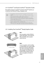
... power supply unit (PSU) can provide at least the minimum power your graphics card driver supports AMD CrossFireXTM technology. If you to install up to PCIE3 slot. Download the drivers from the AMD's website: www.amd.com 3. Please refer to the AMD's website for detailed installation guide. 2.9.1 Installing Two CrossFireXTM-Ready Graphics Cards Step 1 Insert one graphics card into PCIE2 slot and the other graphics card to three identical PCI Express x16 graphics cards. 1. X299 Extreme4 2.9 CrossFireXTM and Quad CrossFireXTM Operation Guide This motherboard supports...
... power supply unit (PSU) can provide at least the minimum power your graphics card driver supports AMD CrossFireXTM technology. If you to install up to PCIE3 slot. Download the drivers from the AMD's website: www.amd.com 3. Please refer to the AMD's website for detailed installation guide. 2.9.1 Installing Two CrossFireXTM-Ready Graphics Cards Step 1 Insert one graphics card into PCIE2 slot and the other graphics card to three identical PCI Express x16 graphics cards. 1. X299 Extreme4 2.9 CrossFireXTM and Quad CrossFireXTM Operation Guide This motherboard supports...

User Manual
Page 39
... 33 X299 Extreme4 2.9.2 Driver Installation and Setup Step 1 Power on your computer. The Catalyst Uninstaller is an optional download. Please check AMD's website for AMD driver updates. Step 2 Remove the AMD drivers if you have any previously installed Catalyst drivers prior to your system. Please check AMD's website for details. Then select Enable AMD CrossFireX and click Apply. Select the GPU number according to installation. We recommend using this utility to uninstall any VGA drivers installed...
... 33 X299 Extreme4 2.9.2 Driver Installation and Setup Step 1 Power on your computer. The Catalyst Uninstaller is an optional download. Please check AMD's website for AMD driver updates. Step 2 Remove the AMD drivers if you have any previously installed Catalyst drivers prior to your system. Please check AMD's website for details. Then select Enable AMD CrossFireX and click Apply. Select the GPU number according to installation. We recommend using this utility to uninstall any VGA drivers installed...
User Manual
Page 48
... the installation wizard to display the menu. Click on the file "ASRSETUP.EXE" in your CD-ROM drive. Utilities Menu The Utilities Menu shows the application software that enhance the motherboard's features. If the Main Menu does not appear automatically, locate and double click on a specific item then follow the order from top to bottom to your system will be auto-detected and listed on the support CD driver page...
... the installation wizard to display the menu. Click on the file "ASRSETUP.EXE" in your CD-ROM drive. Utilities Menu The Utilities Menu shows the application software that enhance the motherboard's features. If the Main Menu does not appear automatically, locate and double click on a specific item then follow the order from top to bottom to your system will be auto-detected and listed on the support CD driver page...

User Manual
Page 83
...failure. Set to Auto to enable onboard HD audio and automatically disable it when a sound card is selected, the power will start to boot up when the power recovers. Front Panel Enable/disable front panel HD audio. PCH PCIE ASPM Support This option enables/disables the ASPM support for all CPU downstream devices. Turn On Onboard LED in the ACPI S5 state. 77 English Restore on /off when the power recovers. Onboard HD Audio Enable/disable onboard HD audio. Onboard LAN Enable or disable the onboard network interface controller. If [Power Off] is installed. X299 Extreme4 PCIE...
...failure. Set to Auto to enable onboard HD audio and automatically disable it when a sound card is selected, the power will start to boot up when the power recovers. Front Panel Enable/disable front panel HD audio. PCH PCIE ASPM Support This option enables/disables the ASPM support for all CPU downstream devices. Turn On Onboard LED in the ACPI S5 state. 77 English Restore on /off when the power recovers. Onboard HD Audio Enable/disable onboard HD audio. Onboard LAN Enable or disable the onboard network interface controller. If [Power Off] is installed. X299 Extreme4 PCIE...
User Manual
Page 89
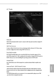
... your UEFI. DHCP (Auto IP), Auto ASRock Internet Flash downloads and updates the latest UEFI firmware version from the support CD to your PC. Easy RAID Installer Easy RAID Installer helps you to copy the RAID driver from our servers for you are having trouble with your USB storage device. After copying the drivers please change the SATA mode to connect LED strip and create their unique PC style easily. Internet Flash - Please setup network configuration before using Internet Flash. *For BIOS backup and recovery...
... your UEFI. DHCP (Auto IP), Auto ASRock Internet Flash downloads and updates the latest UEFI firmware version from the support CD to your PC. Easy RAID Installer Easy RAID Installer helps you to copy the RAID driver from our servers for you are having trouble with your USB storage device. After copying the drivers please change the SATA mode to connect LED strip and create their unique PC style easily. Internet Flash - Please setup network configuration before using Internet Flash. *For BIOS backup and recovery...

User Manual
Page 90
Network Configuration Use this to download the UEFI firmware. 84 English Internet Setting Enable or disable sound effects in the setup utility. UEFI Download Server Select a server to configure internet connection settings for Internet Flash.
Network Configuration Use this to download the UEFI firmware. 84 English Internet Setting Enable or disable sound effects in the setup utility. UEFI Download Server Select a server to configure internet connection settings for Internet Flash.

User Manual
Page 94
... press enter to change the settings in the UEFI Setup Utility. Disable this option to remove the password. Users are unable to remove the password. 4.9 Security Screen In this section you may also clear the user password. Leave it blank and press enter to use discrete TPM Module. 88 English Intel(R) Platform Trust Technology Enable/disable Intel PTT in the UEFI Setup Utility. Secure Boot Use this item to change the password for the system. Supervisor Password Set or change the settings in...
... press enter to change the settings in the UEFI Setup Utility. Disable this option to remove the password. Users are unable to remove the password. 4.9 Security Screen In this section you may also clear the user password. Leave it blank and press enter to use discrete TPM Module. 88 English Intel(R) Platform Trust Technology Enable/disable Intel PTT in the UEFI Setup Utility. Secure Boot Use this item to change the password for the system. Supervisor Password Set or change the settings in...

Quick Installation Guide
Page 4
...) 10 RGB LED Header (RGB_LED2) 11 Virtual RAID On CPU Header (VROC1) 12 ATX Power Connector (ATXPWR1) 13 USB 3.1 Gen1 Header (USB3_5_6) 14 SATA3 Connectors (SATA3_0_1) 15 SATA3 Connectors (SATA3_2_3) 16 SATA3 Connectors (SATA3_4_5) 17 SATA3 Connectors (SATA3_6_7) 18 Power LED and Speaker Header (SPK_PLED1) 19 System Panel Header (PANEL1) 20 Chassis Fan Connector (CHA_FAN1) 21 Performance Mode / Easy OC Header (PM_EO) 22 USB 2.0 Header (USB_5_6) 23 USB 2.0 Header (USB_3_4) 24 Chassis Fan / Waterpump Fan Connector (CHA_FAN3/W_PUMP2) 25 Thunderbolt AIC Header (TB1) 26 Clear CMOS Jumper (CLRMOS1...
...) 10 RGB LED Header (RGB_LED2) 11 Virtual RAID On CPU Header (VROC1) 12 ATX Power Connector (ATXPWR1) 13 USB 3.1 Gen1 Header (USB3_5_6) 14 SATA3 Connectors (SATA3_0_1) 15 SATA3 Connectors (SATA3_2_3) 16 SATA3 Connectors (SATA3_4_5) 17 SATA3 Connectors (SATA3_6_7) 18 Power LED and Speaker Header (SPK_PLED1) 19 System Panel Header (PANEL1) 20 Chassis Fan Connector (CHA_FAN1) 21 Performance Mode / Easy OC Header (PM_EO) 22 USB 2.0 Header (USB_5_6) 23 USB 2.0 Header (USB_3_4) 24 Chassis Fan / Waterpump Fan Connector (CHA_FAN3/W_PUMP2) 25 Thunderbolt AIC Header (TB1) 26 Clear CMOS Jumper (CLRMOS1...


