
Intel Rapid Storage Guide
Page 12
... motherboard to enable RAID in the system BIOS, a RAID volume must be created, and the F6 installation method must be enabled in the system BIOS. 1. When the Intel Rapid Storage Technology option ROM status screen appears during operating system setup. Select 1: Create RAID Volume and press Enter. 3. Use the up or down arrow keys to scroll through the list of hard drives by using the up or down arrow keys to save the BIOS settings...
... motherboard to enable RAID in the system BIOS, a RAID volume must be created, and the F6 installation method must be enabled in the system BIOS. 1. When the Intel Rapid Storage Technology option ROM status screen appears during operating system setup. Select 1: Create RAID Volume and press Enter. 3. Use the up or down arrow keys to scroll through the list of hard drives by using the up or down arrow keys to save the BIOS settings...
Intel Rapid Storage Guide
Page 13
... Device. 3. Setup will happen immediately after pressing F6. Use the Floppy Configuration Utility to scroll through the list as all controllers may not be prompted Note with the Note necessary files. 4. Leave 13 Select the volume size and press Enter. 8. Nothing will temporarily continue loading drivers. Use the up and down arrow keys to create a floppy disk with a screen asking you need to confirm your controller and continue. 7. Press Enter...
... Device. 3. Setup will happen immediately after pressing F6. Use the Floppy Configuration Utility to scroll through the list as all controllers may not be prompted Note with the Note necessary files. 4. Leave 13 Select the volume size and press Enter. 8. Nothing will temporarily continue loading drivers. Use the up and down arrow keys to create a floppy disk with a screen asking you need to confirm your controller and continue. 7. Press Enter...

Intel Rapid Storage Guide
Page 16
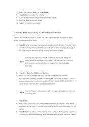
... use a USB floppy drive or create a slipstream version of the final package. This message appears at the beginning of Windows setup (during operating system installation. You will then be used to load the Intel® Rapid Storage Technology driver during text-mode phase). You can use the F6 installation method to install a RAID Note driver on your system, you can use the Floppy Configuration Utility to create a floppy disk with a screen asking you to load support for mass storage device(s). 2. Use...
... use a USB floppy drive or create a slipstream version of the final package. This message appears at the beginning of Windows setup (during operating system installation. You will then be used to load the Intel® Rapid Storage Technology driver during text-mode phase). You can use the F6 installation method to install a RAID Note driver on your system, you can use the Floppy Configuration Utility to create a floppy disk with a screen asking you to load support for mass storage device(s). 2. Use...

RAID Installation Guide
Page 7
... your SATA / SATA2 / SATA3 HDDs with just one simple click in your system, and press key to enter BIOS setup utility. Go to Advanced Storage Configuration and set RAID configuration. 2.3 Installing Windows® 10 64-bit With RAID Functions If you want to install Windows® 10 64-bit OS on your system. 7 Follow the onscreen instruction to save the configuration changes and exit setup. Press [Enter] to confirm the selection C. Plug in UEFI setup. Boot your USB flash drive into a USB port B.
... your SATA / SATA2 / SATA3 HDDs with just one simple click in your system, and press key to enter BIOS setup utility. Go to Advanced Storage Configuration and set RAID configuration. 2.3 Installing Windows® 10 64-bit With RAID Functions If you want to install Windows® 10 64-bit OS on your system. 7 Follow the onscreen instruction to save the configuration changes and exit setup. Press [Enter] to confirm the selection C. Plug in UEFI setup. Boot your USB flash drive into a USB port B.

RAID Installation Guide
Page 23
... the files into a USB flash disk or copy the files from ASRock's motherboard support CD. (Please copy the files under the following directory: 32 bit: ..\i386\Win7_Intel.. 64-bit: ..\AMD64\Win7-64_Intel.. Please make sure to boot. 23 STEP 2: Install Windows® 10 64-bit OS Press to launch boot menu at system POST and choose the item "UEFI:" to use Windows® 10 64-bit. Installing Windows® on a HDD larger than 2TB in RAID mode Windows...
... the files into a USB flash disk or copy the files from ASRock's motherboard support CD. (Please copy the files under the following directory: 32 bit: ..\i386\Win7_Intel.. 64-bit: ..\AMD64\Win7-64_Intel.. Please make sure to boot. 23 STEP 2: Install Windows® 10 64-bit OS Press to launch boot menu at system POST and choose the item "UEFI:" to use Windows® 10 64-bit. Installing Windows® on a HDD larger than 2TB in RAID mode Windows...

User Manual
Page 5
... Specifications 2 1.3 Motherboard Layout 8 1.4 I/O Panel 10 1.5 WiFi-802.11ax Module and ASRock WiFi 2.4/5 GHz Antenna 12 1.6 ASRock Thunderbolt™ 3 Module 13 Chapter 2 Installation 17 2.1 Installing the CPU 18 2.2 Installing the CPU Fan and Heatsink 21 2.3 Installation of Memory Modules (DIMM) 22 2.4 Expansion Slots (PCI Express Slots) 24 2.5 Jumpers Setup 27 2.6 Onboard Headers and Connectors 28 2.7 Smart Switches 35 2.8 Dr. Debug 36 2.9 SLITM and 3-Way SLITMand Operation Guide 42 2.9.1 Installing Two SLITM-Ready Graphics Cards 42 2.9.2 Installing Three...
... Specifications 2 1.3 Motherboard Layout 8 1.4 I/O Panel 10 1.5 WiFi-802.11ax Module and ASRock WiFi 2.4/5 GHz Antenna 12 1.6 ASRock Thunderbolt™ 3 Module 13 Chapter 2 Installation 17 2.1 Installing the CPU 18 2.2 Installing the CPU Fan and Heatsink 21 2.3 Installation of Memory Modules (DIMM) 22 2.4 Expansion Slots (PCI Express Slots) 24 2.5 Jumpers Setup 27 2.6 Onboard Headers and Connectors 28 2.7 Smart Switches 35 2.8 Dr. Debug 36 2.9 SLITM and 3-Way SLITMand Operation Guide 42 2.9.1 Installing Two SLITM-Ready Graphics Cards 42 2.9.2 Installing Three...
User Manual
Page 8
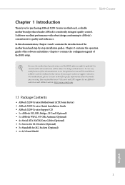
... the configuration guide of the software and utilities. You may find the latest VGA cards and CPU support list on ASRock's website without notice. Chapter 3 contains the operation guide of the BIOS setup. If you require technical support related to this documentation occur, the updated version will be subject to quality and endurance. X299 Creator Chapter 1 Introduction Thank you for M.2 Sockets (Optional) • 1 x I/O Panel Shield 1 English Because the motherboard specifications and the BIOS software might...
... the configuration guide of the software and utilities. You may find the latest VGA cards and CPU support list on ASRock's website without notice. Chapter 3 contains the operation guide of the BIOS setup. If you require technical support related to this documentation occur, the updated version will be subject to quality and endurance. X299 Creator Chapter 1 Introduction Thank you for M.2 Sockets (Optional) • 1 x I/O Panel Shield 1 English Because the motherboard specifications and the BIOS software might...

User Manual
Page 12
X299 Creator *** Ultra USB Power is supported on USB3_34 ports. *** ACPI wake-up function is not supported on USB3_34 ports. • 2 x RJ-45 LAN Ports with LED (ACT/LINK LED and SPEED LED) • 1 x Clear CMOS Button • HD Audio Jacks: Rear Speaker / Central / Bass / Line in / Front Speaker / Microphone (Gold Audio Jacks) Storage • 8 x SATA3 6.0 Gb/s Connectors, support RAID (RAID 0, RAID 1, RAID 5, RAID 10, Intel Rapid Storage Technology 17 and Intel Smart Response Technology), NCQ, AHCI and Hot Plug* * If M2_3 is occupied by a SATA-type M.2 device, SATA3_7 will be...
X299 Creator *** Ultra USB Power is supported on USB3_34 ports. *** ACPI wake-up function is not supported on USB3_34 ports. • 2 x RJ-45 LAN Ports with LED (ACT/LINK LED and SPEED LED) • 1 x Clear CMOS Button • HD Audio Jacks: Rear Speaker / Central / Bass / Line in / Front Speaker / Microphone (Gold Audio Jacks) Storage • 8 x SATA3 6.0 Gb/s Connectors, support RAID (RAID 0, RAID 1, RAID 5, RAID 10, Intel Rapid Storage Technology 17 and Intel Smart Response Technology), NCQ, AHCI and Hot Plug* * If M2_3 is occupied by a SATA-type M.2 device, SATA3_7 will be...

User Manual
Page 13
...if 3-pin or 4-pin fan is in use. • 1 x 24 pin ATX Power Connector (Hi-Density Power Con- tor) • 1 x Front Panel Audio Connector (15μ Gold Audio Connec- tor) • 2 x USB 2.0 Headers (Support 4 USB 2.0 ports) (Supports ESD Protection) • 1 x USB 3.2 Gen1 Header (Supports 2 USB 3.2 Gen1 ports) (Supports ESD Protection) • 1 x Front Panel Type C USB 3.2 Gen2 Header (ASMedia ASM3142) • 1 x Dr. Debug with LED • 1 x Power Button with LED • 1 x Reset Button BIOS Feature • 2 x AMI UEFI Legal BIOS with multilingual GUI support (1 x Main BIOS and...
...if 3-pin or 4-pin fan is in use. • 1 x 24 pin ATX Power Connector (Hi-Density Power Con- tor) • 1 x Front Panel Audio Connector (15μ Gold Audio Connec- tor) • 2 x USB 2.0 Headers (Support 4 USB 2.0 ports) (Supports ESD Protection) • 1 x USB 3.2 Gen1 Header (Supports 2 USB 3.2 Gen1 ports) (Supports ESD Protection) • 1 x Front Panel Type C USB 3.2 Gen2 Header (ASMedia ASM3142) • 1 x Dr. Debug with LED • 1 x Power Button with LED • 1 x Reset Button BIOS Feature • 2 x AMI UEFI Legal BIOS with multilingual GUI support (1 x Main BIOS and...

User Manual
Page 16
... Header (SPI_TPM_J1) 21 Power LED and Speaker Header (SPK_PLED1) 22 System Panel Header (PANEL1) 23 Power Button (PWRBTN1) 24 Reset Button (RSTBTN1) 25 Chassis / Waterpump Fan Connector (CHA_FAN2/WP) 26 Clear CMOS Jumper (CLRMOS1) 27 Chassis / Waterpump Fan Connector (CHA_FAN3/WP) 28 Chassis / Waterpump Fan Connector (CHA_FAN4/WP) 29 USB 2.0 Header (USB5_6) 30 USB 2.0 Header (USB3_4) 31 Addressable LED Header (ADDR_LED1) 32 RGB LED Header (RGB_HEADER1) 33 Virtual RAID On CPU Header (VROC1) 34 Chassis / Waterpump Fan Connector (CHA_FAN5/WP) 35 Front Panel Audio Header (HD_AUDIO1) X299 Creator...
... Header (SPI_TPM_J1) 21 Power LED and Speaker Header (SPK_PLED1) 22 System Panel Header (PANEL1) 23 Power Button (PWRBTN1) 24 Reset Button (RSTBTN1) 25 Chassis / Waterpump Fan Connector (CHA_FAN2/WP) 26 Clear CMOS Jumper (CLRMOS1) 27 Chassis / Waterpump Fan Connector (CHA_FAN3/WP) 28 Chassis / Waterpump Fan Connector (CHA_FAN4/WP) 29 USB 2.0 Header (USB5_6) 30 USB 2.0 Header (USB3_4) 31 Addressable LED Header (ADDR_LED1) 32 RGB LED Header (RGB_HEADER1) 33 Virtual RAID On CPU Header (VROC1) 34 Chassis / Waterpump Fan Connector (CHA_FAN5/WP) 35 Front Panel Audio Header (HD_AUDIO1) X299 Creator...

User Manual
Page 36
... boot time, use Intel® X299 SATA ports (SATA3_0~7) for internal storage devices with up to this motherboard. These ten SATA3 connectors support SATA data cables for your bootable devices. * If M2_3 is one header on this motherboard. GND IntA_PB_SSTX+ IntA_PB_SSTX- Vbus IntA_PA_D+ IntA_PA_DGND IntA_PA_SSTX+ IntA_PA_SSTXGND IntA_PA_SSRX+ IntA_PA_SSRXVbus There is occupied by a SATA-type M.2 device, SATA3_7 will be disabled. Each USB 2.0 header can support two ports. 29 GND IntA_PB_SSRX+ IntA_PB_SSRX- X299 Creator Power LED and Speaker Header (7-pin SPK_PLED1...
... boot time, use Intel® X299 SATA ports (SATA3_0~7) for internal storage devices with up to this motherboard. These ten SATA3 connectors support SATA data cables for your bootable devices. * If M2_3 is one header on this motherboard. GND IntA_PB_SSTX+ IntA_PB_SSTX- Vbus IntA_PA_D+ IntA_PA_DGND IntA_PA_SSTX+ IntA_PA_SSTXGND IntA_PA_SSRX+ IntA_PA_SSRXVbus There is occupied by a SATA-type M.2 device, SATA3_7 will be disabled. Each USB 2.0 header can support two ports. 29 GND IntA_PB_SSRX+ IntA_PB_SSRX- X299 Creator Power LED and Speaker Header (7-pin SPK_PLED1...

User Manual
Page 39
... users to page 67 for the CPU and not the graphics card. Do not plug the PCIe power cable to connect RGB LED extension cable which can securely store keys, digital certificates, passwords, and data. RGB LED Headers (4-pin RGB_HEADER1) (see p.8, No. 32) (4-pin RGB_HEADER2) (see p.8, No. 3) 8 5 This motherboard provides two 8-pin ATX 4 1 12V power connectors. To use a 4-pin ATX power supply, please plug it along Pin 1 and Pin 5. *Warning: Please make sure that the power cable connected is for further instructions on this connector...
... users to page 67 for the CPU and not the graphics card. Do not plug the PCIe power cable to connect RGB LED extension cable which can securely store keys, digital certificates, passwords, and data. RGB LED Headers (4-pin RGB_HEADER1) (see p.8, No. 32) (4-pin RGB_HEADER2) (see p.8, No. 3) 8 5 This motherboard provides two 8-pin ATX 4 1 12V power connectors. To use a 4-pin ATX power supply, please plug it along Pin 1 and Pin 5. *Warning: Please make sure that the power cable connected is for further instructions on this connector...

User Manual
Page 54
... detailed installation guide. 2.10.1 Installing Two CrossFireXTM-Ready Graphics Cards Step 1 Insert one graphics card into PCIE1 slot and the other graphics card to three identical PCI Express x16 graphics cards. You should only use a AMD certified PSU. Make sure that the cards are AMD certified. 2. X299 Creator 2.10 CrossFireXTM and 3-Way CrossFireXTM Operation Guide This motherboard supports CrossFireXTM and 3-way CrossFireXTM that allows you to install up to PCIE3 slot. Please refer to AMD graphics card manuals for...
... detailed installation guide. 2.10.1 Installing Two CrossFireXTM-Ready Graphics Cards Step 1 Insert one graphics card into PCIE1 slot and the other graphics card to three identical PCI Express x16 graphics cards. You should only use a AMD certified PSU. Make sure that the cards are AMD certified. 2. X299 Creator 2.10 CrossFireXTM and 3-Way CrossFireXTM Operation Guide This motherboard supports CrossFireXTM and 3-way CrossFireXTM that allows you to install up to PCIE3 slot. Please refer to AMD graphics card manuals for...
User Manual
Page 57
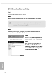
... optional download. English 50 Please check AMD's website for AMD driver updates. Then select Enable AMD CrossFireX and click Apply. Step 3 Install the required drivers and CATALYST Control Center then restart your computer and boot into OS. We recommend using this utility to uninstall any VGA drivers installed in the Windows® system tray. 2.10.3 Driver Installation and Setup Step 1 Power on your computer. Step 2 Remove the AMD drivers if you have any previously installed Catalyst drivers...
... optional download. English 50 Please check AMD's website for AMD driver updates. Then select Enable AMD CrossFireX and click Apply. Step 3 Install the required drivers and CATALYST Control Center then restart your computer and boot into OS. We recommend using this utility to uninstall any VGA drivers installed in the Windows® system tray. 2.10.3 Driver Installation and Setup Step 1 Power on your computer. Step 2 Remove the AMD drivers if you have any previously installed Catalyst drivers...
User Manual
Page 64
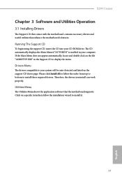
..., the drivers you install can work properly. If the Main Menu does not appear automatically, locate and double click on the file "ASRSETUP.EXE" in your system will be auto-detected and listed on a specific item then follow the order from top to bottom to display the menu. X299 Creator Chapter 3 Software and Utilities Operation 3.1 Installing Drivers The Support CD that comes with the motherboard contains necessary drivers and useful utilities that the motherboard supports...
..., the drivers you install can work properly. If the Main Menu does not appear automatically, locate and double click on the file "ASRSETUP.EXE" in your system will be auto-detected and listed on a specific item then follow the order from top to bottom to display the menu. X299 Creator Chapter 3 Software and Utilities Operation 3.1 Installing Drivers The Support CD that comes with the motherboard contains necessary drivers and useful utilities that the motherboard supports...

User Manual
Page 100
Onboard LAN Enable or disable the onboard network interface controller. Onboard HD Audio Enable/disable onboard HD audio. Bluetooth Enable/disable the Bluetooth's connectivity. Set to Auto to enable onboard HD audio and automatically disable it when a sound card is shut down. 93 English Deep Sleep Configure deep sleep mode for all PCH PCIE devices. PCH DMI ASPM Support This option enables/disables the ASPM support for power saving when the computer is installed. Front Panel Enable/disable front panel HD audio. Onboard WAN Device Enable/disable the onboard WAN device. PCIE5 Link...
Onboard LAN Enable or disable the onboard network interface controller. Onboard HD Audio Enable/disable onboard HD audio. Bluetooth Enable/disable the Bluetooth's connectivity. Set to Auto to enable onboard HD audio and automatically disable it when a sound card is shut down. 93 English Deep Sleep Configure deep sleep mode for all PCH PCIE devices. PCH DMI ASPM Support This option enables/disables the ASPM support for power saving when the computer is installed. Front Panel Enable/disable front panel HD audio. Onboard WAN Device Enable/disable the onboard WAN device. PCIE5 Link...

User Manual
Page 108
SSD Secure Erase Tool Use this tool to your USB storage device. 4.7 Tools X299 Creator UEFI Tech Service Contact ASRock Tech Service if you are having trouble with your UEFI. 101 English Please setup network configuration before using UEFI Tech Service. Instant Flash Save UEFI files in your USB storage device and run Instant Flash to RAID, then you can start installing the operating system in RAID mode. Easy RAID Installer Easy RAID Installer helps you sanitize SSD, all user data will be permantly destroyed on...
SSD Secure Erase Tool Use this tool to your USB storage device. 4.7 Tools X299 Creator UEFI Tech Service Contact ASRock Tech Service if you are having trouble with your UEFI. 101 English Please setup network configuration before using UEFI Tech Service. Instant Flash Save UEFI files in your USB storage device and run Instant Flash to RAID, then you can start installing the operating system in RAID mode. Easy RAID Installer Easy RAID Installer helps you sanitize SSD, all user data will be permantly destroyed on...

User Manual
Page 109
... setup network configuration before using this function. Normally, the system will take over. Internet Flash - DHCP (Auto IP), Auto ASRock Internet Flash downloads and updates the latest UEFI firmware version from our servers for you. Use "Secure Backup UEFI" to duplicate a working ROM image to update the backup BIOS manually. For safety issues, users are outdated or corrupted, switch to the other flash ROM and execute Secure Backup UEFI to duplicate the current working copy of the ROM...
... setup network configuration before using this function. Normally, the system will take over. Internet Flash - DHCP (Auto IP), Auto ASRock Internet Flash downloads and updates the latest UEFI firmware version from our servers for you. Use "Secure Backup UEFI" to duplicate a working ROM image to update the backup BIOS manually. For safety issues, users are outdated or corrupted, switch to the other flash ROM and execute Secure Backup UEFI to duplicate the current working copy of the ROM...

User Manual
Page 110
UEFI Download Server Select a server to configure internet connection settings for Internet Flash. English 103 X299 Creator Internet Setting Enable or disable sound effects in the setup utility. Network Configuration Use this to download the UEFI firmware.
UEFI Download Server Select a server to configure internet connection settings for Internet Flash. English 103 X299 Creator Internet Setting Enable or disable sound effects in the setup utility. Network Configuration Use this to download the UEFI firmware.

User Manual
Page 115
... remove the password. Secure Boot Use this item to remove the password. Leave it blank and press enter to change the supervisor/user password for Windows 8.1 Secure Boot. User Password Set or change the settings in ME. Users are unable to use discrete TPM Module. 108 English Disable this option to change the password for the administrator account. 4.9 Security Screen In this section you may also clear the user password. Intel(R) Platform Trust Technology Enable/disable Intel PTT in the UEFI Setup Utility...
... remove the password. Secure Boot Use this item to remove the password. Leave it blank and press enter to change the supervisor/user password for Windows 8.1 Secure Boot. User Password Set or change the settings in ME. Users are unable to use discrete TPM Module. 108 English Disable this option to change the password for the administrator account. 4.9 Security Screen In this section you may also clear the user password. Intel(R) Platform Trust Technology Enable/disable Intel PTT in the UEFI Setup Utility...


