
User Manual
Page 2
... this manual are used only for any defect or error in Perchlorate Best Management Practices (BMP) regulations passed by ASRock. ASRock assumes no event shall ASRock, its directors, officers, employees, or agents be liable for any indirect, special, incidental, or consequential damages (...must accept any kind, either expressed or implied, including but not limited to infringe. Products and corporate names appearing in this motherboard contains Perchlorate, a toxic substance controlled in the manual or product. In no responsibility for identification or explanation and to the ...
... this manual are used only for any defect or error in Perchlorate Best Management Practices (BMP) regulations passed by ASRock. ASRock assumes no event shall ASRock, its directors, officers, employees, or agents be liable for any indirect, special, incidental, or consequential damages (...must accept any kind, either expressed or implied, including but not limited to infringe. Products and corporate names appearing in this motherboard contains Perchlorate, a toxic substance controlled in the manual or product. In no responsibility for identification or explanation and to the ...
User Manual
Page 3
Contents 1 Introduction 5 1.1 Package Contents 5 1.2 Specifications 6 1.3 Minimum Hardware Requirement Table for Windows® VistaTM Premium 2007 and Basic Logo 9 1.4 Motherboard Layout 10 1.5 ASRock 6CH Premium I/O 11 2 Installation 12 2.1 Screw Holes 12 2.2 Pre-installation Precautions 12 2.3 CPU Installation 13 2.4 Installation of Heatsink and CPU fan 15 2.5 Installation of Memory ...
Contents 1 Introduction 5 1.1 Package Contents 5 1.2 Specifications 6 1.3 Minimum Hardware Requirement Table for Windows® VistaTM Premium 2007 and Basic Logo 9 1.4 Motherboard Layout 10 1.5 ASRock 6CH Premium I/O 11 2 Installation 12 2.1 Screw Holes 12 2.2 Pre-installation Precautions 12 2.3 CPU Installation 13 2.4 Installation of Heatsink and CPU fan 15 2.5 Installation of Memory ...

User Manual
Page 5
.../support/index.asp 1.1 Package Contents ASRock Wolfdale1333-GLAN Motherboard (ATX Form Factor: 12.0-in x 7.5-in, 30.5 cm x 19.1 cm) ASRock Wolfdale1333-GLAN Quick Installation Guide ASRock Wolfdale1333-GLAN Support CD One 80-conductor Ultra ATA 66/100 IDE Ribbon Cable One Ribbon Cable for purchasing ASRock Wolfdale1333-GLAN motherboard, a reliable motherboard produced under ASRock's consistently stringent quality control. ASRock website http://www.asrock.com If you require technical...
.../support/index.asp 1.1 Package Contents ASRock Wolfdale1333-GLAN Motherboard (ATX Form Factor: 12.0-in x 7.5-in, 30.5 cm x 19.1 cm) ASRock Wolfdale1333-GLAN Quick Installation Guide ASRock Wolfdale1333-GLAN Support CD One 80-conductor Ultra ATA 66/100 IDE Ribbon Cable One Ribbon Cable for purchasing ASRock Wolfdale1333-GLAN motherboard, a reliable motherboard produced under ASRock's consistently stringent quality control. ASRock website http://www.asrock.com If you require technical...

User Manual
Page 8
...wireless local area network (WLAN) adapter. Under this situation, PCIE frequency will automatically shutdown. This motherboard supports Dual Channel Memory Technology. WiFi header supports WiFi+AP function with ASRock WiFi-802.11g or WiFi-802.11n module, an easy-to 115MHz. 2. Please visit our...bus frequencies may be overclocked to -use a FSB1333-CPU on the motherboard functions properly and unplug the power cord, then plug it back again. While CPU overheat is not recom- ASRock website http://www.asrock.com 8 FSB1333-CPU will run at DDRII500 if you to SATAII...
...wireless local area network (WLAN) adapter. Under this situation, PCIE frequency will automatically shutdown. This motherboard supports Dual Channel Memory Technology. WiFi header supports WiFi+AP function with ASRock WiFi-802.11g or WiFi-802.11n module, an easy-to 115MHz. 2. Please visit our...bus frequencies may be overclocked to -use a FSB1333-CPU on the motherboard functions properly and unplug the power cord, then plug it back again. While CPU overheat is not recom- ASRock website http://www.asrock.com 8 FSB1333-CPU will run at DDRII500 if you to SATAII...
User Manual
Page 9
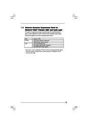
1 . 3 Minimum Hardware Requirement Table for Windows® VistaTM Premium 2007 and Basic Logo For system integrators and users who purchase this motherboard and plan to qualify for minimum hardware requirements. CPU Memory VGA Celeron D 326 1GB system memory (Premium) 512MB Single Channel (Basic) DX9.0 with WDDM Driver ...
1 . 3 Minimum Hardware Requirement Table for Windows® VistaTM Premium 2007 and Basic Logo For system integrators and users who purchase this motherboard and plan to qualify for minimum hardware requirements. CPU Memory VGA Celeron D 326 1GB system memory (Premium) 512MB Single Channel (Basic) DX9.0 with WDDM Driver ...
User Manual
Page 10
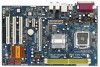
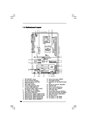
Orange) 12 SATAII Connector (SATAII_4 (PORT3); Red) 14 SATAII Connector (SATAII_1 (PORT0); 1.4 Motherboard Layout PS2 Keyboard 1 23 4 19.1cm (7.5 in) PS2 Mouse 1 PS2_USB_PWR1 ATX12V1 56 CPU_FAN1 PARALLEL PORT Dual Core CPU Wolfdale COM1 DDRII_2 (64/72 ... SPK Bottom: CTR BASS Top: LINE IN Center: FRONT Bottom: MIC IN Gigabit LAN 29 28 27 26 5.1CH HD LAN Super I/O PCI EXPRESS PCIE1 Wolfdale1333-GLAN PCIE2 PCIE3 CMOS Battery 1 CLRCMOS1 IDE1 PCI1 HDMI_SPDIF1 1 1 AUDIO CODEC CD1 HD_AUDIO1 1 PCI2 WIFI RoHS PCI3 FLOPPY1 Intel ICH7 USB45 1 CHA_FAN1 4Mb BIOS IR1 1...
Orange) 12 SATAII Connector (SATAII_4 (PORT3); Red) 14 SATAII Connector (SATAII_1 (PORT0); 1.4 Motherboard Layout PS2 Keyboard 1 23 4 19.1cm (7.5 in) PS2 Mouse 1 PS2_USB_PWR1 ATX12V1 56 CPU_FAN1 PARALLEL PORT Dual Core CPU Wolfdale COM1 DDRII_2 (64/72 ... SPK Bottom: CTR BASS Top: LINE IN Center: FRONT Bottom: MIC IN Gigabit LAN 29 28 27 26 5.1CH HD LAN Super I/O PCI EXPRESS PCIE1 Wolfdale1333-GLAN PCIE2 PCIE3 CMOS Battery 1 CLRCMOS1 IDE1 PCI1 HDMI_SPDIF1 1 1 AUDIO CODEC CD1 HD_AUDIO1 1 PCI2 WIFI RoHS PCI3 FLOPPY1 Intel ICH7 USB45 1 CHA_FAN1 4Mb BIOS IR1 1...

User Manual
Page 12
...is an ATX form factor (12.0" x 7.5", 30.5 x 19.1 cm) motherboard. Before you and damages to do so may damage the motherboard. 2.2 Pre-installation Precautions Take note of your motherboard directly on a grounded antistatic pad or in the bag that comes with the ... you uninstall any component, place it . To avoid damaging the motherboard components due to static electricity, NEVER place your chassis to unplug the power cord before installing or removing the motherboard. Chapter 2 Installation Wolfdale1333-GLAN is detached from the wall socket before touching any component. 2....
...is an ATX form factor (12.0" x 7.5", 30.5 x 19.1 cm) motherboard. Before you and damages to do so may damage the motherboard. 2.2 Pre-installation Precautions Take note of your motherboard directly on a grounded antistatic pad or in the bag that comes with the ... you uninstall any component, place it . To avoid damaging the motherboard components due to static electricity, NEVER place your chassis to unplug the power cord before installing or removing the motherboard. Chapter 2 Installation Wolfdale1333-GLAN is detached from the wall socket before touching any component. 2....

User Manual
Page 14
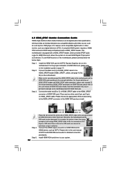
Step 3. This cap must be placed if returning the motherboard for after service. Close the socket: Step 4-1. Rotate the load plate onto the IHS. Step 4-2. Remove PnP Cap (Pick and Place Cap): Use your left ...
Step 3. This cap must be placed if returning the motherboard for after service. Close the socket: Step 4-1. Rotate the load plate onto the IHS. Step 4-2. Remove PnP Cap (Pick and Place Cap): Use your left ...

User Manual
Page 15
... with 775-Pin socket that the CPU and the heatsink are oriented on the motherboard (CPU_FAN1, see page 10, No. 4). Step 4. Connect fan header with the motherboard throughholes. 2.4 Installation of CPU Fan and Heatsink This motherboard is an example to dissipate heat. Ensure that supports Intel 775-LAND CPU. ... interface material onto center of the heatsink for 775-LAND CPU. Step 3. Align fasteners with the CPU fan connector on the motherboard. Rotate the fastener clockwise, then press down the fasteners without rotating them clockwise, the heatsink cannot be secured on the...
... with 775-Pin socket that the CPU and the heatsink are oriented on the motherboard (CPU_FAN1, see page 10, No. 4). Step 4. Connect fan header with the motherboard throughholes. 2.4 Installation of CPU Fan and Heatsink This motherboard is an example to dissipate heat. Ensure that supports Intel 775-LAND CPU. ... interface material onto center of the heatsink for 775-LAND CPU. Step 3. Align fasteners with the CPU fan connector on the motherboard. Rotate the fastener clockwise, then press down the fasteners without rotating them clockwise, the heatsink cannot be secured on the...

User Manual
Page 16
... orientation. If you install only one correct orientation. Step 1. Firmly insert the DIMM into DDRII slot; It will cause permanent damage to the motherboard and the DIMM if you always need to install two identical (the same brand, speed, size and chip-type) memory modules in one memory...the DIMM is not allowed to disconnect power supply before adding or removing DIMMs or the system components. 2.5 Installation of Memory Modules (DIMM) Wolfdale1333-GLAN motherboard provides two 240-pin DDRII (Double Data Rate) DIMM slots, and supports Dual Channel Memory Technology.
... orientation. If you install only one correct orientation. Step 1. Firmly insert the DIMM into DDRII slot; It will cause permanent damage to the motherboard and the DIMM if you always need to install two identical (the same brand, speed, size and chip-type) memory modules in one memory...the DIMM is not allowed to disconnect power supply before adding or removing DIMMs or the system components. 2.5 Installation of Memory Modules (DIMM) Wolfdale1333-GLAN motherboard provides two 240-pin DDRII (Double Data Rate) DIMM slots, and supports Dual Channel Memory Technology.

User Manual
Page 17
... Express Slots) There are used for PCI Express cards with x16 lane width graphics cards. PCIE2 / PCIE3 (PCIE x1 slot) is completely seated on this motherboard.
... Express Slots) There are used for PCI Express cards with x16 lane width graphics cards. PCIE2 / PCIE3 (PCIE x1 slot) is completely seated on this motherboard.

User Manual
Page 19
...connector connect to the power supply Please connect the black end of the SATA data cable can be connected to the power connector on the motherboard. The current SATAII interface allows up to the power connector of the connector. SATAII_1 SATAII_2 (PORT0) (PORT1) Serial ATA (SATA) ...(PORT2): see p.10, No. 11) (SATAII_4 (PORT3): see p.10 No. 22) Pin1 FLOPPY1 the red-striped side to the instruction of the motherboard! Then connect the white end of SATA power cable to 3.0 Gb/s data transfer rate. 2.8 Onboard Headers and Connectors Onboard headers and connectors are NOT ...
...connector connect to the power supply Please connect the black end of the SATA data cable can be connected to the power connector on the motherboard. The current SATAII interface allows up to the power connector of the connector. SATAII_1 SATAII_2 (PORT0) (PORT1) Serial ATA (SATA) ...(PORT2): see p.10, No. 11) (SATAII_4 (PORT3): see p.10 No. 22) Pin1 FLOPPY1 the red-striped side to the instruction of the motherboard! Then connect the white end of SATA power cable to 3.0 Gb/s data transfer rate. 2.8 Onboard Headers and Connectors Onboard headers and connectors are NOT ...

User Manual
Page 20
...(see p.10 No. 23) USB+5V_2 NC NC GND2 NC+3SVB 1 GND1 NC D0-D0+ USB+5V_1 This header supports WiFi+AP function with ASRock WiFi-802.11g or WiFi-802.11n module, an easy-to create a wireless environment and enjoy the convenience of audio devices. 1. DeskExpress Hot Plug...Panel Audio Header (9-pin HD_AUDIO1) (see p.10 No. 25) GND PRESENCE# MIC_RET OUT_RET 1 OUT2_L J_SENSE OUT2_R MIC2_R MIC2_L This is one USB 2.0 header on this motherboard. This connector allows you to -use wireless local area network (WLAN) adapter. This USB 2.0 header can support two USB 2.0 ports. USB 2.0 Header (9-pin ...
...(see p.10 No. 23) USB+5V_2 NC NC GND2 NC+3SVB 1 GND1 NC D0-D0+ USB+5V_1 This header supports WiFi+AP function with ASRock WiFi-802.11g or WiFi-802.11n module, an easy-to create a wireless environment and enjoy the convenience of audio devices. 1. DeskExpress Hot Plug...Panel Audio Header (9-pin HD_AUDIO1) (see p.10 No. 25) GND PRESENCE# MIC_RET OUT_RET 1 OUT2_L J_SENSE OUT2_R MIC2_R MIC2_L This is one USB 2.0 header on this motherboard. This connector allows you to -use wireless local area network (WLAN) adapter. This USB 2.0 header can support two USB 2.0 ports. USB 2.0 Header (9-pin ...

User Manual
Page 22
... nect HDMI Digital TV/ projector/LCD devices. Please connect the HDMI_SPDIF connector of HDMI VGA card to this motherboard, please connect it to this connector. 1 13 Though this motherboard provides 24-pin ATX power connector, 12 24 it can work if you plan to connect the 3-Pin...(see p.10 No. 2) HDMI_SPDIF Header (3-pin HDMI_SPDIF1) (see p.10, No. 3) 12 24 Please connect an ATX power supply to Pin 1-3. Though this motherboard provides 4-Pin CPU fan (Quiet Fan) support, the 3-Pin CPU fan still can provides sufficient power. If you adopt a traditional 20-pin ATX power supply....
... nect HDMI Digital TV/ projector/LCD devices. Please connect the HDMI_SPDIF connector of HDMI VGA card to this motherboard, please connect it to this connector. 1 13 Though this motherboard provides 24-pin ATX power connector, 12 24 it can work if you plan to connect the 3-Pin...(see p.10 No. 2) HDMI_SPDIF Header (3-pin HDMI_SPDIF1) (see p.10, No. 3) 12 24 Please connect an ATX power supply to Pin 1-3. Though this motherboard provides 4-Pin CPU fan (Quiet Fan) support, the 3-Pin CPU fan still can provides sufficient power. If you adopt a traditional 20-pin ATX power supply....

User Manual
Page 23
Then connect the white end (B or C) of HDMI VGA card. white end (2-pin) SPDIFOUT GND blue black C. A. white end (3-pin) SPDIFOUT GND blue black 23 HDMI_SPDIF Cable (Optional) C B A Please connect the black end (A) of HDMI_SPDIF cable to the HDMI_SPDIF connector of HDMI_SPDIF cable to the HDMI_SPDIF header on the motherboard. black end +5V SPDIFOUT GND blue black B.
Then connect the white end (B or C) of HDMI VGA card. white end (2-pin) SPDIFOUT GND blue black C. A. white end (3-pin) SPDIFOUT GND blue black 23 HDMI_SPDIF Cable (Optional) C B A Please connect the black end (A) of HDMI_SPDIF cable to the HDMI_SPDIF connector of HDMI_SPDIF cable to the HDMI_SPDIF header on the motherboard. black end +5V SPDIFOUT GND blue black B.
User Manual
Page 24
... driver to the VGA card user manual for detailed connection procedures. Make sure to correctly connect the HDMI_SPDIF cable to the motherboard and the HDMI VGA card according to the HDMI_SPDIF connector of HDMI_SPDIF connectors on HDMI_SPDIF cable. Please choose the appropriate white ...(A) of HDTV and HDMI VGA card vendor for connector usage in advance. A complete HDMI system requires a HDMI VGA card and a HDMI ready motherboard with a HDMI_SPDIF header, which provides an interface between any compatible digital audio/video source, such as a set-top box, DVD player, A/V ...
... driver to the VGA card user manual for detailed connection procedures. Make sure to correctly connect the HDMI_SPDIF cable to the motherboard and the HDMI VGA card according to the HDMI_SPDIF connector of HDMI_SPDIF connectors on HDMI_SPDIF cable. Please choose the appropriate white ...(A) of HDTV and HDMI VGA card vendor for connector usage in advance. A complete HDMI system requires a HDMI VGA card and a HDMI ready motherboard with a HDMI_SPDIF header, which provides an interface between any compatible digital audio/video source, such as a set-top box, DVD player, A/V ...
User Manual
Page 26
...those required drivers. Please follow the order from [Auto] to [CPU, PCIE, Async.]. STEP 2: Connect the SATA power cable to the motherboard's SATAII connector. Then, the drivers compatible to your system can be auto-detected and listed on page 7 for internal storage devices. Please ... means during overclocking, FSB enjoys better margin due to fixed PCI / PCIE buses. You may install SATA / SATAII hard disks on this motherboard for the possible overclocking risk before you install can operate under a more stable overclocking environment. STEP 1: Install the SATA / SATAII hard disks...
...those required drivers. Please follow the order from [Auto] to [CPU, PCIE, Async.]. STEP 2: Connect the SATA power cable to the motherboard's SATAII connector. Then, the drivers compatible to your system can be auto-detected and listed on page 7 for internal storage devices. Please ... means during overclocking, FSB enjoys better margin due to fixed PCI / PCIE buses. You may install SATA / SATAII hard disks on this motherboard for the possible overclocking risk before you install can operate under a more stable overclocking environment. STEP 1: Install the SATA / SATAII hard disks...

User Manual
Page 27
... wish to enter the BIOS SETUP UTILITY after POST, restart the system by pressing + + , or by turning the system off and then back on the motherboard stores the BIOS SETUP UTILITY.
... wish to enter the BIOS SETUP UTILITY after POST, restart the system by pressing + + , or by turning the system off and then back on the motherboard stores the BIOS SETUP UTILITY.
User Manual
Page 30
...Microsoft® Windows® XP, or Linux 30 The C1 state is a read -only item, which displays the ratio actual value of this motherboard. NT4.0) cannot handle the function with "No Execute (NX) Memory Protection" can utilize the additional hardware capabilities provided by malicious software to execute ... To enable this feature, it shows "Unlocked", you will find this item appear to allow you changing the ratio value of this motherboard. This option will be hidden if the current CPU does not support No-Excute Memory Protection. Ratio Actual Value This is supported through...
...Microsoft® Windows® XP, or Linux 30 The C1 state is a read -only item, which displays the ratio actual value of this motherboard. NT4.0) cannot handle the function with "No Execute (NX) Memory Protection" can utilize the additional hardware capabilities provided by malicious software to execute ... To enable this feature, it shows "Unlocked", you will find this item appear to allow you changing the ratio value of this motherboard. This option will be hidden if the current CPU does not support No-Excute Memory Protection. Ratio Actual Value This is supported through...

User Manual
Page 31
is selected, the motherboard will be hidden if the installed CPU does not support Hyper-Threading technology. Please set the "Power Schemes" as operating frequency: [200MHz (DDRII 400)], [266MHz (...
is selected, the motherboard will be hidden if the installed CPU does not support Hyper-Threading technology. Please set the "Power Schemes" as operating frequency: [200MHz (DDRII 400)], [266MHz (...

