
User Manual
Page 2
... this manual. When you discard the Lithium battery in California, USA, please follow the related regulations in Perchlorate Best Management Practices (BMP) regulations passed by ASRock. With respect to the contents of this motherboard contains Perchlorate, a toxic substance controlled in advance. CALIFORNIA, USA ONLY The Lithium battery adopted on this manual...
... this manual. When you discard the Lithium battery in California, USA, please follow the related regulations in Perchlorate Best Management Practices (BMP) regulations passed by ASRock. With respect to the contents of this motherboard contains Perchlorate, a toxic substance controlled in advance. CALIFORNIA, USA ONLY The Lithium battery adopted on this manual...

User Manual
Page 3
Contents 1 Introduction 5 1.1 Package Contents 5 1.2 Specifications 6 1.3 Motherboard Layout 10 1.4 ASRock 6CH I/O PlusTM 11 2 Installation 12 2.1 Screw Holes 12 2.2 Pre-installation Precautions 12 2.3 CPU Installation 13 2.4 Installation of Heatsink and CPU fan 15 2.5 Installation of Memory Modules (DIMM 16 2.6 Expansion Slots (PCI and PCI Express Slots 17 2.7 DVI Graphics-SI Card Installation Guide 18 2.8 Jumpers Setup...
Contents 1 Introduction 5 1.1 Package Contents 5 1.2 Specifications 6 1.3 Motherboard Layout 10 1.4 ASRock 6CH I/O PlusTM 11 2 Installation 12 2.1 Screw Holes 12 2.2 Pre-installation Precautions 12 2.3 CPU Installation 13 2.4 Installation of Heatsink and CPU fan 15 2.5 Installation of Memory Modules (DIMM 16 2.6 Expansion Slots (PCI and PCI Express Slots 17 2.7 DVI Graphics-SI Card Installation Guide 18 2.8 Jumpers Setup...
User Manual
Page 5
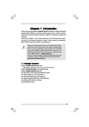
... using. You may find the latest VGA cards and CPU support lists on ASRock website without notice. www.asrock.com/support/index.asp 1.1 Package Contents ASRock Wolfdale1333-DVI Motherboard (Micro ATX Form Factor: 9.6-in x 8.7-in, 24.4 cm x 22.1 cm) ASRock Wolfdale1333-DVI Quick Installation Guide ASRock Wolfdale1333-DVI Support CD One 80-conductor Ultra ATA 66/100 IDE Ribbon Cable One Ribbon...
... using. You may find the latest VGA cards and CPU support lists on ASRock website without notice. www.asrock.com/support/index.asp 1.1 Package Contents ASRock Wolfdale1333-DVI Motherboard (Micro ATX Form Factor: 9.6-in x 8.7-in, 24.4 cm x 22.1 cm) ASRock Wolfdale1333-DVI Quick Installation Guide ASRock Wolfdale1333-DVI Support CD One 80-conductor Ultra ATA 66/100 IDE Ribbon Cable One Ribbon...

User Manual
Page 8
...to perform over-clocking. Please read "Untied Overclocking Technology" on page 26 for the CPU FSB frequency and its corre- This motherboard supports Dual Channel Memory Technology. Please check the table below for details. 4. The maximum shared memory size is defined by the...adopt a DDRII533 memory module. 6. FSB1333-CPU will automatically shutdown. Before you resume the system, please check if the CPU fan on this motherboard, it back again. sponding memory support frequency. CAUTION! 1. To improve heat dissipation, remember to read the "SATAII Hard Disk Setup Guide...
...to perform over-clocking. Please read "Untied Overclocking Technology" on page 26 for the CPU FSB frequency and its corre- This motherboard supports Dual Channel Memory Technology. Please check the table below for details. 4. The maximum shared memory size is defined by the...adopt a DDRII533 memory module. 6. FSB1333-CPU will automatically shutdown. Before you resume the system, please check if the CPU fan on this motherboard, it back again. sponding memory support frequency. CAUTION! 1. To improve heat dissipation, remember to read the "SATAII Hard Disk Setup Guide...

User Manual
Page 10
... 2 x 240-pin DDRII DIMM Slots 20 WiFi Header (WIFI) (Dual Channel: DDRII_1, DDRII_2; Orange) 27 Shared USB 2.0 Header (USB2_3, Blue) 10 1.3 Motherboard Layout 12 34 56 7 22.1cm (8.7 in) 1 PS2_USB_PWR1 ATX12V1 PS2 Mouse PS2 Keyboard DDRII_2 (64/72 bit, 240F-pSinBm8o0d0ule) DDRII_1 (64/72 bit, 240F-... Core CPU PARALLEL PORT COM1 VGA1 USB2_3 1 27 26 25 24 23 22 21 Top: Line In Center: Line Out Bottom: Mic In Dual Channel Wolfdale1333-DVI USB 2.0 T: USB2 B: USB3 USB 2.0 T: USB0 B: USB1 Top: RJ-45 USB 2.0 T: USB4 B: USB5 USB2.0 Super IO CPU_FAN1 1 IR1 ATXPWR1 Intel...
... 2 x 240-pin DDRII DIMM Slots 20 WiFi Header (WIFI) (Dual Channel: DDRII_1, DDRII_2; Orange) 27 Shared USB 2.0 Header (USB2_3, Blue) 10 1.3 Motherboard Layout 12 34 56 7 22.1cm (8.7 in) 1 PS2_USB_PWR1 ATX12V1 PS2 Mouse PS2 Keyboard DDRII_2 (64/72 bit, 240F-pSinBm8o0d0ule) DDRII_1 (64/72 bit, 240F-... Core CPU PARALLEL PORT COM1 VGA1 USB2_3 1 27 26 25 24 23 22 21 Top: Line In Center: Line Out Bottom: Mic In Dual Channel Wolfdale1333-DVI USB 2.0 T: USB2 B: USB3 USB 2.0 T: USB0 B: USB1 Top: RJ-45 USB 2.0 T: USB4 B: USB5 USB2.0 Super IO CPU_FAN1 1 IR1 ATXPWR1 Intel...

User Manual
Page 12
... that comes with the component. Hold components by circles to secure the motherboard to use a grounded wrist strap or touch a safety grounded object before installing or removing the motherboard. Chapter 2 Installation Wolfdale1333-DVI is detached from the wall socket before you install motherboard components or change any component. 2. Failure to do so may cause physical...
... that comes with the component. Hold components by circles to secure the motherboard to use a grounded wrist strap or touch a safety grounded object before installing or removing the motherboard. Chapter 2 Installation Wolfdale1333-DVI is detached from the wall socket before you install motherboard components or change any component. 2. Failure to do so may cause physical...

User Manual
Page 14
... from the socket while pressing on load plate, engage the load lever. Close the socket: Step 4-1. Step 2-3. This cap must be placed if returning the motherboard for after service. Step 4-2. It is within the socket and properly mated to support the load plate edge, engage PnP cap with load plate tab...
... from the socket while pressing on load plate, engage the load lever. Close the socket: Step 4-1. Step 2-3. This cap must be placed if returning the motherboard for after service. Step 4-2. It is within the socket and properly mated to support the load plate edge, engage PnP cap with load plate tab...

User Manual
Page 15
...your CPU fan and heatsink. Step 6. Secure excess cable with tie-wrap to ensure cable does not interfere with the CPU fan connector on the motherboard. Then connect the CPU fan to the CPU_FAN connector (CPU_FAN1, see page 10, No. 4). Step 1. Step 4. Step 5. Connect fan ...fan operation or contact other . Before you installed the heatsink, you press down on the motherboard (CPU_FAN1, see page 10, No. 4). Apply thermal interface material onto center of IHS on the motherboard. Rotate the fastener clockwise, then press down the fasteners without rotating them clockwise, the ...
...your CPU fan and heatsink. Step 6. Secure excess cable with tie-wrap to ensure cable does not interfere with the CPU fan connector on the motherboard. Then connect the CPU fan to the CPU_FAN connector (CPU_FAN1, see page 10, No. 4). Step 1. Step 4. Step 5. Connect fan ...fan operation or contact other . Before you installed the heatsink, you press down on the motherboard (CPU_FAN1, see page 10, No. 4). Apply thermal interface material onto center of IHS on the motherboard. Rotate the fastener clockwise, then press down the fasteners without rotating them clockwise, the ...

User Manual
Page 16
... will cause permanent damage to activate Dual Channel Memory Technology. Step 2. 2.5 Installation of Memory Modules (DIMM) Wolfdale1333-DVI motherboard provides two 240-pin DDRII (Double Data Rate) DIMM slots, and supports Dual Channel Memory Technology. otherwise, this motherboard and DIMM may be damaged. 2. notch break notch break The DIMM only fits in place and...
... will cause permanent damage to activate Dual Channel Memory Technology. Step 2. 2.5 Installation of Memory Modules (DIMM) Wolfdale1333-DVI motherboard provides two 240-pin DDRII (Double Data Rate) DIMM slots, and supports Dual Channel Memory Technology. otherwise, this motherboard and DIMM may be damaged. 2. notch break notch break The DIMM only fits in place and...

User Manual
Page 17
...-SI card to install to PCIE1 (PCIE x16 slot). Keep the screws for PCI Express cards with x16 lane width graphics cards or ASRock DVI Graphics-SI card. Step 4. Please read the documentation of the expansion card and make sure that the power supply is switched off or the power ... slots are 2 PCI slots and 2 PCI Express slots on the slot. Installing an expansion card Step 1. PCIE2 (PCIE x1 slot) is completely seated on this motherboard. Align the card connector with screws. 17 Step 3. Remove the bracket facing the slot that you install the add-on PCI Express VGA card to...
...-SI card to install to PCIE1 (PCIE x16 slot). Keep the screws for PCI Express cards with x16 lane width graphics cards or ASRock DVI Graphics-SI card. Step 4. Please read the documentation of the expansion card and make sure that the power supply is switched off or the power ... slots are 2 PCI slots and 2 PCI Express slots on the slot. Installing an expansion card Step 1. PCIE2 (PCIE x1 slot) is completely seated on this motherboard. Align the card connector with screws. 17 Step 3. Remove the bracket facing the slot that you install the add-on PCI Express VGA card to...

User Manual
Page 18
... card which is inserted to PCIE1 (PCIE x16 slot) on this motherboard. Install the DVI Graphics-SI card to below procedures for details. DVI-D connector of DVI-D monitor DVI-D output connector of our DVI Graphics-SI card, this motherboard provides users with dual VGA output support: DVI-D and D-Sub. Please refer to PCIE1 (PCIE x16 slot). Connect the...
... card which is inserted to PCIE1 (PCIE x16 slot) on this motherboard. Install the DVI Graphics-SI card to below procedures for details. DVI-D connector of DVI-D monitor DVI-D output connector of our DVI Graphics-SI card, this motherboard provides users with dual VGA output support: DVI-D and D-Sub. Please refer to PCIE1 (PCIE x16 slot). Connect the...

User Manual
Page 19
Step 4. Then you can freely enjoy the benefits of this motherboard. If you haven't installed Intel® VGA driver yet, please install Intel® VGA driver from our support CD to your system already, you have installed Intel® VGA driver from our support CD to your system and restart your system boots. Connect the D-Sub monitor to use DVI-D output function with this motherboard. 19 If you can start to the VGA/D-Sub port on the I/O panel of DVI-D output function with this motherboard after your computer. Step 3.
Step 4. Then you can freely enjoy the benefits of this motherboard. If you haven't installed Intel® VGA driver yet, please install Intel® VGA driver from our support CD to your system already, you have installed Intel® VGA driver from our support CD to your system and restart your system boots. Connect the D-Sub monitor to use DVI-D output function with this motherboard. 19 If you can start to the VGA/D-Sub port on the I/O panel of DVI-D output function with this motherboard after your computer. Step 3.

User Manual
Page 21
... end of your IDE device vendor for internal storage devices. Then connect the white end of SATA power cable to the power connector on the motherboard. Primary IDE connector (Blue) (39-pin IDE1, see p.10 No. 8) PIN1 IDE1 connect the blue end connect the black end to the... the IDE devices 80-conductor ATA 66/100 cable Note: Please refer to the instruction of SATA power cable to the power connector of the motherboard! Either end of the connector. Serial ATAII Connectors (SATAII_1: see p.10, No. 11) (SATAII_2: see p.10, No. 15) (SATAII_3: see p.10, No. 12) (SATAII_4: see...
... end of your IDE device vendor for internal storage devices. Then connect the white end of SATA power cable to the power connector on the motherboard. Primary IDE connector (Blue) (39-pin IDE1, see p.10 No. 8) PIN1 IDE1 connect the blue end connect the black end to the... the IDE devices 80-conductor ATA 66/100 cable Note: Please refer to the instruction of SATA power cable to the power connector of the motherboard! Either end of the connector. Serial ATAII Connectors (SATAII_1: see p.10, No. 11) (SATAII_2: see p.10, No. 15) (SATAII_3: see p.10, No. 12) (SATAII_4: see...

User Manual
Page 22
... panel USB cable to USB4_5 header, the USB ports 23 on the I /O panel, there is one USB 2.0 header on this motherboard. This is shared with ASRock WiFi-802.11g / WiFi-802.11n module, an easy-to-use wireless local area network (WLAN) adapter. It allows you to ...allows you to create a wireless environment and enjoy the convenience of audio devices. The shared USB 2.0 header (USB4_5) is an interface for ASRock DeskExpress. This header supports the Hot Plug detection function for front panel audio cable that allows convenient connection and control of wireless network connectivity....
... panel USB cable to USB4_5 header, the USB ports 23 on the I /O panel, there is one USB 2.0 header on this motherboard. This is shared with ASRock WiFi-802.11g / WiFi-802.11n module, an easy-to-use wireless local area network (WLAN) adapter. It allows you to ...allows you to create a wireless environment and enjoy the convenience of audio devices. The shared USB 2.0 header (USB4_5) is an interface for ASRock DeskExpress. This header supports the Hot Plug detection function for front panel audio cable that allows convenient connection and control of wireless network connectivity....

User Manual
Page 24
...power. To use the 20-pin ATX power supply, please plug your power supply along with ATX 12V plug to this motherboard provides 24-pin ATX power connector, it can work if you plan to connect the 3-Pin CPU fan to the ...CPU fan connector on this motherboard provides 4-Pin CPU fan (Quiet Fan) support, the 3-Pin CPU fan still can still work successfully even without the fan...pin ATX power supply. Failing to do so will cause the failure to power up. 24 Though this motherboard, please connect it to Pin 1-3.
...power. To use the 20-pin ATX power supply, please plug your power supply along with ATX 12V plug to this motherboard provides 24-pin ATX power connector, it can work if you plan to connect the 3-Pin CPU fan to the ...CPU fan connector on this motherboard provides 4-Pin CPU fan (Quiet Fan) support, the 3-Pin CPU fan still can still work successfully even without the fan...pin ATX power supply. Failing to do so will cause the failure to power up. 24 Though this motherboard, please connect it to Pin 1-3.

User Manual
Page 26
...4: Connect the other end of the SATA data cable to the warning on this motherboard for the possible overclocking risk before you install can work properly. 2 . 1 3 Untied Overclocking Technology This motherboard supports Untied Overclocking Technology, which means during overclocking, but PCI / PCIE buses are... in the fixed mode so that supports Serial ATA (SATA) / Serial ATAII (SATAII) hard disks. Please refer to the motherboard's SATAII connector. Therefore, CPU FSB is untied during overclocking, FSB enjoys better margin due to install the SATA / SATAII hard disks. ...
...4: Connect the other end of the SATA data cable to the warning on this motherboard for the possible overclocking risk before you install can work properly. 2 . 1 3 Untied Overclocking Technology This motherboard supports Untied Overclocking Technology, which means during overclocking, but PCI / PCIE buses are... in the fixed mode so that supports Serial ATA (SATA) / Serial ATAII (SATAII) hard disks. Please refer to the motherboard's SATAII connector. Therefore, CPU FSB is untied during overclocking, FSB enjoys better margin due to install the SATA / SATAII hard disks. ...

User Manual
Page 27
... Chipset To set up the computer. The BIOS FWH chip on the system chassis. You may also restart by pressing the reset button on the motherboard stores the BIOS SETUP UTILITY.
... Chipset To set up the computer. The BIOS FWH chip on the system chassis. You may also restart by pressing the reset button on the motherboard stores the BIOS SETUP UTILITY.

User Manual
Page 30
...function with extended CPUID functions. Hyper Threading Technology To enable this feature, it shows "Unlocked", you changing the ratio value of this motherboard. If it requires a computer system with an Intel Pentium® 4 processor that supports Hyper-Threading technology and an operating system that ...-Excute Memory Protection No-Execution (NX) Memory Protection Technology is a read -only item, which displays the ratio actual value of this motherboard. This option will be enabled in advance. Ratio Actual Value This is an enhancement to the IA-32 Intel Architecture. Max CPUID Value...
...function with extended CPUID functions. Hyper Threading Technology To enable this feature, it shows "Unlocked", you changing the ratio value of this motherboard. If it requires a computer system with an Intel Pentium® 4 processor that supports Hyper-Threading technology and an operating system that ...-Excute Memory Protection No-Execution (NX) Memory Protection Technology is a read -only item, which displays the ratio actual value of this motherboard. This option will be enabled in advance. Ratio Actual Value This is an enhancement to the IA-32 Intel Architecture. Max CPUID Value...

User Manual
Page 31
... will detect the memory module(s) inserted and assigns appropriate frequency automatically. Intel (R) SpeedStep(tm) tech. If you need to set this option is selected, the motherboard will allow better tolerance for memory compatibility when it is set this function, please set to [Enabled]. Please set the "Power Schemes" as operating frequency...
... will detect the memory module(s) inserted and assigns appropriate frequency automatically. Intel (R) SpeedStep(tm) tech. If you need to set this option is selected, the motherboard will allow better tolerance for memory compatibility when it is set this function, please set to [Enabled]. Please set the "Power Schemes" as operating frequency...

User Manual
Page 32
... TRAS. DVMT (Dynamic Video Memory Technology) is available to the graphics core, with other system components. This mode guarantees that offers breakthrough performance for the motherboard through efficient memory utilization. The default value is [PCI]. This item will not be used under Windows® VistaTM OS because the driver will be...
... TRAS. DVMT (Dynamic Video Memory Technology) is available to the graphics core, with other system components. This mode guarantees that offers breakthrough performance for the motherboard through efficient memory utilization. The default value is [PCI]. This item will not be used under Windows® VistaTM OS because the driver will be...

