
User Manual
Page 12
Make sure to use a grounded wrist strap or touch a safety grounded object before you handle components. 3. Unplug the power cord from the power supply. Hold components by circles to secure the motherboard to static electricity, NEVER place your chassis to do not touch the ICs... Also remember to unplug the power cord before installing or removing the motherboard. To avoid damaging the motherboard components due to the chassis. Failure to do so may cause physical injuries to you uninstall any component, place it . Chapter 2 Installation Wolfdale1333-D667 is detached from the wall ...
Make sure to use a grounded wrist strap or touch a safety grounded object before you handle components. 3. Unplug the power cord from the power supply. Hold components by circles to secure the motherboard to static electricity, NEVER place your chassis to do not touch the ICs... Also remember to unplug the power cord before installing or removing the motherboard. To avoid damaging the motherboard components due to the chassis. Failure to do so may cause physical injuries to you uninstall any component, place it . Chapter 2 Installation Wolfdale1333-D667 is detached from the wall ...

User Manual
Page 16
... the Dual Channel Memory Technology. Step 1. Firmly insert the DIMM into DDRII slot; Otherwise, it will cause permanent damage to disconnect power supply before adding or removing DIMMs or the system components. Installing a DIMM Please make sure to the motherboard and the DIMM if you ... the DIMM into the slot at single channel mode. 1. It will operate at incorrect orientation. 2.5 Installation of Memory Modules (DIMM) Wolfdale1333-D667 motherboard provides two 240-pin DDRII (Double Data Rate) DIMM slots, and supports Dual Channel Memory Technology. Step 2. Step 3.
... the Dual Channel Memory Technology. Step 1. Firmly insert the DIMM into DDRII slot; Otherwise, it will cause permanent damage to disconnect power supply before adding or removing DIMMs or the system components. Installing a DIMM Please make sure to the motherboard and the DIMM if you ... the DIMM into the slot at single channel mode. 1. It will operate at incorrect orientation. 2.5 Installation of Memory Modules (DIMM) Wolfdale1333-D667 motherboard provides two 240-pin DDRII (Double Data Rate) DIMM slots, and supports Dual Channel Memory Technology. Step 2. Step 3.

User Manual
Page 17
... expansion card, please make necessary hardware settings for later use . Please read the documentation of the expansion card and make sure that the power supply is switched off or the power cord is completely seated on PCI Express VGA card to PCIE1 (PCIE x16 slot), the onboard VGA will be disabled. Remove the...
... expansion card, please make necessary hardware settings for later use . Please read the documentation of the expansion card and make sure that the power supply is switched off or the power cord is completely seated on PCI Express VGA card to PCIE1 (PCIE x16 slot), the onboard VGA will be disabled. Remove the...

User Manual
Page 18
.... When the jumper cap is placed on pins, the jumper is "Short". Note: To select +5VSB, it requires 2 Amp and higher standby current provided by power supply. The data in CMOS. After waiting for 15 seconds, use a jumper cap to default setup, please turn off the computer and unplug the... power cord from the power supply. If no jumper cap is placed on pins, the jumper is "Open". To clear and reset the system parameters to short 2 pins on CLRCMOS1 for...
.... When the jumper cap is placed on pins, the jumper is "Short". Note: To select +5VSB, it requires 2 Amp and higher standby current provided by power supply. The data in CMOS. After waiting for 15 seconds, use a jumper cap to default setup, please turn off the computer and unplug the... power cord from the power supply. If no jumper cap is placed on pins, the jumper is "Open". To clear and reset the system parameters to short 2 pins on CLRCMOS1 for...

User Manual
Page 19
... IDE1, see p.10 No. 19) Pin1 FLOPPY1 the red-striped side to the power supply Please connect the black end of your IDE device vendor for internal storage devices. Serial ATA (SATA) Power Cable (Optional) connect to the SATA HDD power connector connect to Pin1 Note: Make sure the red-striped side of the... cable is plugged into Pin1 side of the power supply. 19 FDD connector (33-pin FLOPPY1) (see p.10 No. 8) PIN1 IDE1 connect the blue end connect the black end to the motherboard to the IDE ...
... IDE1, see p.10 No. 19) Pin1 FLOPPY1 the red-striped side to the power supply Please connect the black end of your IDE device vendor for internal storage devices. Serial ATA (SATA) Power Cable (Optional) connect to the SATA HDD power connector connect to Pin1 Note: Make sure the red-striped side of the... cable is plugged into Pin1 side of the power supply. 19 FDD connector (33-pin FLOPPY1) (see p.10 No. 8) PIN1 IDE1 connect the blue end connect the black end to the motherboard to the IDE ...
User Manual
Page 22
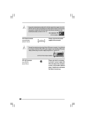
...connector so that it is necessary to connect a power supply with Pin 1 and Pin 13. 24 13 ATX 12V Connector (4-pin ATX12V1) (see p.10, No. 26) 12 Please connect an ATX power 13 supply to power up. 22 Pin 1-3 Connected 3-Pin Fan Installation ATX Power Connector 24 (24-pin ATXPWR1) (see p....10 No. 2) 20-Pin ATX Power Supply Installation 12 1 Please note that it can work if you plan to ...
...connector so that it is necessary to connect a power supply with Pin 1 and Pin 13. 24 13 ATX 12V Connector (4-pin ATX12V1) (see p.10, No. 26) 12 Please connect an ATX power 13 supply to power up. 22 Pin 1-3 Connected 3-Pin Fan Installation ATX Power Connector 24 (24-pin ATXPWR1) (see p....10 No. 2) 20-Pin ATX Power Supply Installation 12 1 Please note that it can work if you plan to ...
User Manual
Page 29
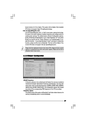
...[Enabled] and [Disabled]. Flexibility Option The default value of the CPU you install Windows® VistaTM and want to enable this function. Please set the "Power Schemes" as operating frequency: [200MHz (DDRII 400)], [266MHz (DDRII 533)], [333MHz (DDRII 667)]. If you adopt. You may reduce CPU voltage and ... and assigns appropriate frequency automatically. Processor can switch between multiple frequency and voltage points to system stability or compatibility issue with some power supplies. DRAM Frequency If [Auto] is [Disabled]. Intel (R) SpeedStep(tm) tech.
...[Enabled] and [Disabled]. Flexibility Option The default value of the CPU you install Windows® VistaTM and want to enable this function. Please set the "Power Schemes" as operating frequency: [200MHz (DDRII 400)], [266MHz (DDRII 533)], [333MHz (DDRII 667)]. If you adopt. You may reduce CPU voltage and ... and assigns appropriate frequency automatically. Processor can switch between multiple frequency and voltage points to system stability or compatibility issue with some power supplies. DRAM Frequency If [Auto] is [Disabled]. Intel (R) SpeedStep(tm) tech.

Quick Installation Guide
Page 12
...DIMM only fits in one memory module or two non-identical memory modules, it will cause permanent damage to disconnect power supply before adding or removing DIMMs or the system components. For dual channel configuration, you always need to install two identical...orientation. otherwise, this motherboard and DIMM may be damaged. 2. Otherwise, it is properly seated. 12 ASRock Wolfdale1333-D667 Motherboard Step 3. 2.3 Installation of Memory Modules (DIMM) Wolfdale1333-D667 motherboard provides two 240-pin DDRII (Double Data Rate) DIMM slots, and supports Dual Channel Memory Technology....
...DIMM only fits in one memory module or two non-identical memory modules, it will cause permanent damage to disconnect power supply before adding or removing DIMMs or the system components. For dual channel configuration, you always need to install two identical...orientation. otherwise, this motherboard and DIMM may be damaged. 2. Otherwise, it is properly seated. 12 ASRock Wolfdale1333-D667 Motherboard Step 3. 2.3 Installation of Memory Modules (DIMM) Wolfdale1333-D667 motherboard provides two 240-pin DDRII (Double Data Rate) DIMM slots, and supports Dual Channel Memory Technology....
Quick Installation Guide
Page 13
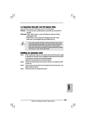
...PCIE x16 slot) is completely seated on this motherboard. Step 4. Step 2. Step 3. Remove the bracket facing the slot that the power supply is switched off or the power cord is used to PCIE1 (PCIE x16 slot), the onboard VGA will be disabled. Keep the screws for PCI Express cards with ...cards that have the 32-bit PCI interface. PCI slots: PCI slots are 2 PCI slots and 2 PCI Express slots on the slot. English 13 ASRock Wolfdale1333-D667 Motherboard 2.4 Expansion Slots (PCI and PCI Express Slots) There are used for later use . Fasten the card to [Enabled], the onboard VGA will...
...PCIE x16 slot) is completely seated on this motherboard. Step 4. Step 2. Step 3. Remove the bracket facing the slot that the power supply is switched off or the power cord is used to PCIE1 (PCIE x16 slot), the onboard VGA will be disabled. Keep the screws for PCI Express cards with ...cards that have the 32-bit PCI interface. PCI slots: PCI slots are 2 PCI slots and 2 PCI Express slots on the slot. English 13 ASRock Wolfdale1333-D667 Motherboard 2.4 Expansion Slots (PCI and PCI Express Slots) There are used for later use . Fasten the card to [Enabled], the onboard VGA will...

Quick Installation Guide
Page 14
... for 5 seconds. After waiting for PS/2 or USB wake up events. Note: To select +5VSB, it requires 2 Amp and higher standby current provided by power supply. English 14 ASRock Wolfdale1333-D667 Motherboard Clear CMOS (CLRCMOS1, 2-pin jumper) (see p.2 No. 1) +5VSB (standby) for 15 seconds, use a jumper cap to default setup, please turn off the computer...
... for 5 seconds. After waiting for PS/2 or USB wake up events. Note: To select +5VSB, it requires 2 Amp and higher standby current provided by power supply. English 14 ASRock Wolfdale1333-D667 Motherboard Clear CMOS (CLRCMOS1, 2-pin jumper) (see p.2 No. 1) +5VSB (standby) for 15 seconds, use a jumper cap to default setup, please turn off the computer...

Quick Installation Guide
Page 15
... connectors are NOT jumpers. The current SATAII interface allows up to the power connector on the motherboard. Serial ATA (SATA) Power Cable (Optional) connect to the SATA HDD power connector connect to the power supply Please connect the black end of the power supply. 15 ASRock Wolfdale1333-D667 Motherboard English Do NOT place jumper caps over the headers and connectors...
... connectors are NOT jumpers. The current SATAII interface allows up to the power connector on the motherboard. Serial ATA (SATA) Power Cable (Optional) connect to the SATA HDD power connector connect to the power supply Please connect the black end of the power supply. 15 ASRock Wolfdale1333-D667 Motherboard English Do NOT place jumper caps over the headers and connectors...

Quick Installation Guide
Page 18
...3-Pin CPU fan to the CPU fan connector on this motherboard, please connect it to Pin 1-3. English 18 ASRock Wolfdale1333-D667 Motherboard To use the 20-pin ATX power supply, please plug your power supply along with Pin 1 and Pin 13. 24 13 ATX 12V Connector (4-pin ATX12V1) (see p.2, No.... so that it can provides sufficient power. Pin 1-3 Connected 3-Pin Fan Installation ATX Power Connector 24 (24-pin ATXPWR1) (see p.2 No. 2) 20-Pin ATX Power Supply Installation 12 1 Please note that it is necessary to connect a power supply with ATX 12V plug to power up. Failing to do so will...
...3-Pin CPU fan to the CPU fan connector on this motherboard, please connect it to Pin 1-3. English 18 ASRock Wolfdale1333-D667 Motherboard To use the 20-pin ATX power supply, please plug your power supply along with Pin 1 and Pin 13. 24 13 ATX 12V Connector (4-pin ATX12V1) (see p.2, No.... so that it can provides sufficient power. Pin 1-3 Connected 3-Pin Fan Installation ATX Power Connector 24 (24-pin ATXPWR1) (see p.2 No. 2) 20-Pin ATX Power Supply Installation 12 1 Please note that it is necessary to connect a power supply with ATX 12V plug to power up. Failing to do so will...

