

User Manual
Page 4
... (PCI Express Slots) 12 2.3 Jumpers Setup 13 2.4 Onboard Headers and Connectors 14 Chapter 3 Software and Utilities Operation 17 3.1 Installing Drivers 17 3.2 ASRock APP Shop 18 3.2.1 UI Overview 18 3.2.2 Apps 19 3.2.3 BIOS & Drivers 22 3.2.4 Setting 23 Chapter 4 UEFI SETUP UTILITY 24 4.1 Introduction 24 4.1.1 UEFI Menu Bar 24 4.1.2 Navigation Keys 25 4.2 Main Screen 26
... (PCI Express Slots) 12 2.3 Jumpers Setup 13 2.4 Onboard Headers and Connectors 14 Chapter 3 Software and Utilities Operation 17 3.1 Installing Drivers 17 3.2 ASRock APP Shop 18 3.2.1 UI Overview 18 3.2.2 Apps 19 3.2.3 BIOS & Drivers 22 3.2.4 Setting 23 Chapter 4 UEFI SETUP UTILITY 24 4.1 Introduction 24 4.1.1 UEFI Menu Bar 24 4.1.2 Navigation Keys 25 4.2 Main Screen 26
User Manual
Page 6
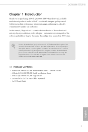
... you for purchasing ASRock QC5000M-ITX/PH motherboard, a reliable motherboard produced under ASRock's consistently stringent quality control. ASRock website http://www.asrock.com. 1.1 Package Contents • ASRock QC5000M-ITX/PH Motherboard (Mini-ITX Form Factor) • ASRock QC5000M-ITX/PH Quick Installation Guide • ASRock QC5000M-ITX/PH Support CD • 2 x Serial ATA (SATA) Data Cables (Optional) • 1 x I/O Panel Shield 1 English Because the motherboard speciications and the BIOS sotware might be...
... you for purchasing ASRock QC5000M-ITX/PH motherboard, a reliable motherboard produced under ASRock's consistently stringent quality control. ASRock website http://www.asrock.com. 1.1 Package Contents • ASRock QC5000M-ITX/PH Motherboard (Mini-ITX Form Factor) • ASRock QC5000M-ITX/PH Quick Installation Guide • ASRock QC5000M-ITX/PH Support CD • 2 x Serial ATA (SATA) Data Cables (Optional) • 1 x I/O Panel Shield 1 English Because the motherboard speciications and the BIOS sotware might be...
User Manual
Page 8
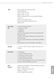
QC5000M-ITX/PH LAN Rear Panel I/O Storage Connector BIOS Feature • PCIE x1 Gigabit LAN 10/100/1000 Mb/s • Realtek RTL8111GR • Supports Wake-On-WAN • Supports Wake-On-LAN • Supports Lightning/ESD Protection (ASRock Full Spike Protection) • ...8226; 1 x Front Panel Audio Connector • 2 x USB 2.0 Headers (Support 4 USB 2.0 ports) (Supports ESD Protection (ASRock Full Spike Protection)) • 32Mb AMI UEFI Legal BIOS with multilingual GUI support • Supports "Plug and Play" • ACPI 1.1 compliance wake up events • SMBIOS 2.3.1 support ...
QC5000M-ITX/PH LAN Rear Panel I/O Storage Connector BIOS Feature • PCIE x1 Gigabit LAN 10/100/1000 Mb/s • Realtek RTL8111GR • Supports Wake-On-WAN • Supports Wake-On-LAN • Supports Lightning/ESD Protection (ASRock Full Spike Protection) • ...8226; 1 x Front Panel Audio Connector • 2 x USB 2.0 Headers (Support 4 USB 2.0 ports) (Supports ESD Protection (ASRock Full Spike Protection)) • 32Mb AMI UEFI Legal BIOS with multilingual GUI support • Supports "Plug and Play" • ACPI 1.1 compliance wake up events • SMBIOS 2.3.1 support ...

User Manual
Page 9
...CE, WHQL • ErP/EuP ready (ErP/EuP ready power supply is required) * For detailed product information, please visit our website: http://www.asrock.com Please realize that Windows® cannot use. It should be less than 4GB for the reservation for system usage under Windows® 8.1 / 8...® 64-bit OS with 64-bit CPU, there is a certain risk involved with overclocking, including adjusting the setting in the BIOS, applying Untied Overclocking Technology, or using thirdparty overclocking tools. Hardware Monitor • CPU/Chassis temperature sensing • CPU/Chassis Fan ...
...CE, WHQL • ErP/EuP ready (ErP/EuP ready power supply is required) * For detailed product information, please visit our website: http://www.asrock.com Please realize that Windows® cannot use. It should be less than 4GB for the reservation for system usage under Windows® 8.1 / 8...® 64-bit OS with 64-bit CPU, there is a certain risk involved with overclocking, including adjusting the setting in the BIOS, applying Untied Overclocking Technology, or using thirdparty overclocking tools. Hardware Monitor • CPU/Chassis temperature sensing • CPU/Chassis Fan ...

User Manual
Page 10
PS2 Keyboard/ Mouse 1.3 Motherboard Layout USB 2.0 T: USB0 B: USB1 QC5000M-ITX/PH 1 CMOS Battery CLRCMOS1 1 2 CHA_FAN1 3 ATXPWR1 QC5000M-ITX/PH DDR3_A1 (64 bit, 240-FpinSBmo8d0ul0e) DDR3_A2 (64 bit, 240-pin module) COM1 VGA1 HDMI1 RoHS USB 3.0 T: USB0 B: USB1 USB 3.0 RJ-45 LAN Top: LINE IN Center: FRONT Bottom: MIC IN USB 2.0 T: USB2 B: USB3 LAN HD_AUDIO1 1 AUDIO CODEC CPU_FAN1 TPMS1 1 USB4_5 1 USB2_3 1 32Mb BIOS SPEAKER1 1 PCIE1 13 12 11 10 9 8 SATA3_1 SATA3_2 4 PANEL 1 PLED PWRBTN 5 1 HDLED RESET 6 7 English 5
PS2 Keyboard/ Mouse 1.3 Motherboard Layout USB 2.0 T: USB0 B: USB1 QC5000M-ITX/PH 1 CMOS Battery CLRCMOS1 1 2 CHA_FAN1 3 ATXPWR1 QC5000M-ITX/PH DDR3_A1 (64 bit, 240-FpinSBmo8d0ul0e) DDR3_A2 (64 bit, 240-pin module) COM1 VGA1 HDMI1 RoHS USB 3.0 T: USB0 B: USB1 USB 3.0 RJ-45 LAN Top: LINE IN Center: FRONT Bottom: MIC IN USB 2.0 T: USB2 B: USB3 LAN HD_AUDIO1 1 AUDIO CODEC CPU_FAN1 TPMS1 1 USB4_5 1 USB2_3 1 32Mb BIOS SPEAKER1 1 PCIE1 13 12 11 10 9 8 SATA3_1 SATA3_2 4 PANEL 1 PLED PWRBTN 5 1 HDLED RESET 6 7 English 5

User Manual
Page 18
...the jumper is placed on these 2 pins. Ater waiting for 5 seconds. However, please do the clear-CMOS action. English 13 QC5000M-ITX/PH 2.3 Jumpers Setup he illustration shows a 3-pin jumper whose pin1 and pin2 are setup. When the jumper cap is placed on ...CLRCMOS1 for 15 seconds, use a jumper cap to clear the CMOS when you just inish updating the BIOS, you must boot up the system irst, and then shut it down before you do not clear the CMOS right...is removed. Clear CMOS Jumper (CLRCMOS1) (see p.5, No. 2) Default Clear CMOS CLRCMOS1 allows you update the BIOS.
...the jumper is placed on these 2 pins. Ater waiting for 5 seconds. However, please do the clear-CMOS action. English 13 QC5000M-ITX/PH 2.3 Jumpers Setup he illustration shows a 3-pin jumper whose pin1 and pin2 are setup. When the jumper cap is placed on ...CLRCMOS1 for 15 seconds, use a jumper cap to clear the CMOS when you just inish updating the BIOS, you must boot up the system irst, and then shut it down before you do not clear the CMOS right...is removed. Clear CMOS Jumper (CLRCMOS1) (see p.5, No. 2) Default Clear CMOS CLRCMOS1 allows you update the BIOS.

User Manual
Page 27
Click on Step 2 to see a list of recommended or critical updates for the BIOS or drivers. Please update them all soon. Step 1 Please check the item information before update. 3.2.3 BIOS & Drivers Installing BIOS or Drivers When the "BIOS & Drivers" tab is selected, you will see more items you want to update. Step 3 Click Update to select one or more details. Click to start the update process. 22 English
Click on Step 2 to see a list of recommended or critical updates for the BIOS or drivers. Please update them all soon. Step 1 Please check the item information before update. 3.2.3 BIOS & Drivers Installing BIOS or Drivers When the "BIOS & Drivers" tab is selected, you will see more items you want to update. Step 3 Click Update to select one or more details. Click to start the update process. 22 English

User Manual
Page 29
You may not exactly match what you see on the computer, otherwise, the Power-On-Self-Test (POST) will it make BIOS setup less diicult but also a lot more amusing. Because the UEFI sotware is a blend of the screen has a menu bar with its test routines. If ... the current screen or the UEFI Setup Utility 24 English You may also restart by pressing the reset button on . Chapter 4 UEFI SETUP UTILITY 4.1 Introduction ASRock Interactive UEFI is constantly being updated, the following UEFI setup screens and descriptions are for reference purpose only, and they may run the UEFI SETUP...
You may not exactly match what you see on the computer, otherwise, the Power-On-Self-Test (POST) will it make BIOS setup less diicult but also a lot more amusing. Because the UEFI sotware is a blend of the screen has a menu bar with its test routines. If ... the current screen or the UEFI Setup Utility 24 English You may also restart by pressing the reset button on . Chapter 4 UEFI SETUP UTILITY 4.1 Introduction ASRock Interactive UEFI is constantly being updated, the following UEFI setup screens and descriptions are for reference purpose only, and they may run the UEFI SETUP...
User Manual
Page 46
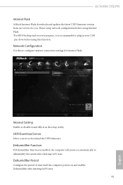
... until the computer powers on automatically to conigure internet connection settings for you. Please setup network coniguration before using Internet Flash. *For BIOS backup and recovery purpose, it is enabled, the computer will power on and enables Dehumidiier ater entering S4/S5 state. 41 English ...If Dehumidiier Function is recommended to download the UEFI irmware. UEFI Download Server Select a server to plug in the setup utility. QC5000M-ITX/PH Internet Flash ASRock Internet Flash downloads and updates the latest UEFI irmware version from our servers for Internet Flash.
... until the computer powers on automatically to conigure internet connection settings for you. Please setup network coniguration before using Internet Flash. *For BIOS backup and recovery purpose, it is enabled, the computer will power on and enables Dehumidiier ater entering S4/S5 state. 41 English ...If Dehumidiier Function is recommended to download the UEFI irmware. UEFI Download Server Select a server to plug in the setup utility. QC5000M-ITX/PH Internet Flash ASRock Internet Flash downloads and updates the latest UEFI irmware version from our servers for Internet Flash.


