
Intel Rapid Storage Guide
Page 12
...select the physical disks. 6. Enetr the Advanced menu. 3. Select 1: Create RAID Volume and press Enter. 3. Press Enter to save the BIOS settings and exit the BIOS Setup program. When finished press Enter. 12 How to install an operating system onto a RAID volume (F6 install method) In order to ...install an operating system onto a RAID volume, the RAID option must be enabled in the system BIOS. 1. The F6 installation method is not required for Microsoft Windows Vista* or Note Microsoft Windows 7*. Click F2 or Delete to enter the option...
...select the physical disks. 6. Enetr the Advanced menu. 3. Select 1: Create RAID Volume and press Enter. 3. Press Enter to save the BIOS settings and exit the BIOS Setup program. When finished press Enter. 12 How to install an operating system onto a RAID volume (F6 install method) In order to ...install an operating system onto a RAID volume, the RAID option must be enabled in the system BIOS. 1. The F6 installation method is not required for Microsoft Windows Vista* or Note Microsoft Windows 7*. Click F2 or Delete to enter the option...
User Manual
Page 5
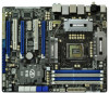
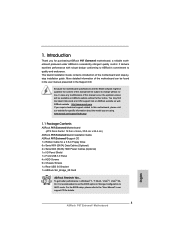
... are using. www.asrock.com/support/index.asp 1.1 Package Contents ASRock P67 Extreme6 Motherboard (ATX Form Factor: 12.0-in x 9.6-in, 30.5 cm x 24.4 cm) ASRock P67 Extreme6 Quick Installation Guide ASRock P67 Extreme6 Support CD 1 x Ribbon Cable for purchasing ASRock P67 Extreme6 motherboard, a reliable motherboard produced under ASRock's consistently stringent quality control. Because the motherboard specifications and the BIOS software might be updated...
... are using. www.asrock.com/support/index.asp 1.1 Package Contents ASRock P67 Extreme6 Motherboard (ATX Form Factor: 12.0-in x 9.6-in, 30.5 cm x 24.4 cm) ASRock P67 Extreme6 Quick Installation Guide ASRock P67 Extreme6 Support CD 1 x Ribbon Cable for purchasing ASRock P67 Extreme6 motherboard, a reliable motherboard produced under ASRock's consistently stringent quality control. Because the motherboard specifications and the BIOS software might be updated...
User Manual
Page 7
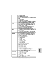
... x Front USB 3.0 header (supports 2 USB 3.0 ports) by Marvell SE9120, support NCQ, AHCI and "Hot Plug" functions (SATA3_M4 connector is shared with LED - 64Mb AMI BIOS - Front panel audio connector - 4 x USB 2.0 headers (support 8 USB 2.0 ports) - 1 x USB 3.0 header (supports 2 USB 3.0 ports) - 1 x Dr.... - 1 x IR header - 1 x COM port header - 1 x HDMI_SPDIF header - 1 x IEEE 1394 header - 1 x Power LED header - SATA3 USB3.0 Connector Smart Switch BIOS Feature - 1 x eSATA3 Connector - 4 x Ready-to-Use USB 3.0 Ports - 2 x RJ-45 LAN Ports with LED (ACT/LINK LED and SPEED LED) - 1 x IEEE...
... x Front USB 3.0 header (supports 2 USB 3.0 ports) by Marvell SE9120, support NCQ, AHCI and "Hot Plug" functions (SATA3_M4 connector is shared with LED - 64Mb AMI BIOS - Front panel audio connector - 4 x USB 2.0 headers (support 8 USB 2.0 ports) - 1 x USB 3.0 header (supports 2 USB 3.0 ports) - 1 x Dr.... - 1 x IR header - 1 x COM port header - 1 x HDMI_SPDIF header - 1 x IEEE 1394 header - 1 x Power LED header - SATA3 USB3.0 Connector Smart Switch BIOS Feature - 1 x eSATA3 Connector - 4 x Ready-to-Use USB 3.0 Ports - 2 x RJ-45 LAN Ports with LED (ACT/LINK LED and SPEED LED) - 1 x IEEE...
User Manual
Page 8
... CD - CPU Frequency Stepless Control (see CAUTION 14) * For detailed product information, please visit our website: http://www.asrock.com WARNING Please realize that there is required) (see CAUTION 11) - CPU/Chassis Quiet Fan (Allow Chassis Fan Speed Auto...is a certain risk involved with overclocking, including adjusting the setting in the BIOS, applying Untied Overclocking Technology, or using the third-party overclocking tools. ASRock Extreme Tuning Utility (AXTU) (see CAUTION 8) - ASRock AIWI (see CAUTION 6) - Good Night LED Hardware - CPU/Chassis Fan...
... CD - CPU Frequency Stepless Control (see CAUTION 14) * For detailed product information, please visit our website: http://www.asrock.com WARNING Please realize that there is required) (see CAUTION 11) - CPU/Chassis Quiet Fan (Allow Chassis Fan Speed Auto...is a certain risk involved with overclocking, including adjusting the setting in the BIOS, applying Untied Overclocking Technology, or using the third-party overclocking tools. ASRock Extreme Tuning Utility (AXTU) (see CAUTION 8) - ASRock AIWI (see CAUTION 6) - Good Night LED Hardware - CPU/Chassis Fan...
User Manual
Page 9
... Tuning Utility (AXTU). Please check the table on the processor. ASRock website: http://www.asrock.com 7. In Hardware Monitor, it shows the fan speed and temperature for the operation procedures of "Hyper Threading Technology", please check page 68. 2. This convenient BIOS update tool allows you can reduce the number of output phases to...
... Tuning Utility (AXTU). Please check the table on the processor. ASRock website: http://www.asrock.com 7. In Hardware Monitor, it shows the fan speed and temperature for the operation procedures of "Hyper Threading Technology", please check page 68. 2. This convenient BIOS update tool allows you can reduce the number of output phases to...

User Manual
Page 14
... PCIE1 CODEC Dual GLAN 46 PCIE2 RoHS 64Mb BIOS CrossFireX 45 PCI1 1394a ErP/EuP Ready CLRCMOS1 44 PCIE3 1 CMOS Intel Super I/O Battery PCI Express 2.0 P67 SATA3_0_1 Front USB 3.0 SATA3_M3_M4 SATA3_M1_M2 43 42 41 40 39 PCIE4 P67 Extreme6 PCI2 Designed in Taipei 1 HDMI_SPDIF1 IR1 PCIE5 ... White) 18 SATA3 Connector (SATA3_M1, White) 19 SATA3 Connector (SATA3_M4, White) 20 SATA3 Connector (SATA3_M3, White) 21 Dr. Debug 22 Intel P67 Chipset 23 Reset Switch (RSTBTN) 24 Power Switch (PWRBTN) 25 Power LED Header (PLED1) 26 Chassis Speaker Header (SPEAKER 1, White) 27 System...
... PCIE1 CODEC Dual GLAN 46 PCIE2 RoHS 64Mb BIOS CrossFireX 45 PCI1 1394a ErP/EuP Ready CLRCMOS1 44 PCIE3 1 CMOS Intel Super I/O Battery PCI Express 2.0 P67 SATA3_0_1 Front USB 3.0 SATA3_M3_M4 SATA3_M1_M2 43 42 41 40 39 PCIE4 P67 Extreme6 PCI2 Designed in Taipei 1 HDMI_SPDIF1 IR1 PCIE5 ... White) 18 SATA3 Connector (SATA3_M1, White) 19 SATA3 Connector (SATA3_M4, White) 20 SATA3 Connector (SATA3_M3, White) 21 Dr. Debug 22 Intel P67 Chipset 23 Reset Switch (RSTBTN) 24 Power Switch (PWRBTN) 25 Power LED Header (PLED1) 26 Chassis Speaker Header (SPEAKER 1, White) 27 System...

User Manual
Page 34
.... 37) the red-striped side to clear the data in CMOS. If you need to clear the CMOS when you just finish updating the BIOS, you must boot up the system first, and then shut it down before you to Pin1 Note: Make sure the red-striped side of...-pin FLOPPY1) (see p.14, No. 32) Setting Default Clear CMOS Description Note: CLRCMOS1 allows you do not clear the CMOS right after you update the BIOS. To clear and reset the system parameters to short pin2 and pin3 on these headers and connectors. However, please do the clear-CMOS action. After...
.... 37) the red-striped side to clear the data in CMOS. If you need to clear the CMOS when you just finish updating the BIOS, you must boot up the system first, and then shut it down before you to Pin1 Note: Make sure the red-striped side of...-pin FLOPPY1) (see p.14, No. 32) Setting Default Clear CMOS Description Note: CLRCMOS1 allows you do not clear the CMOS right after you update the BIOS. To clear and reset the system parameters to short pin2 and pin3 on these headers and connectors. However, please do the clear-CMOS action. After...

User Manual
Page 81
...). Normally it is the device which contains your Windows® installation files. Installing OS on a HDD Larger Than 2TB This motherboard is adopting UEFI BIOS that allows Windows® OS to install the operating system. 1. Start Windows® installation. 81 Set AHCI Mode in UEFI Setup Utility > Advanced > Storage Con...
...). Normally it is the device which contains your Windows® installation files. Installing OS on a HDD Larger Than 2TB This motherboard is adopting UEFI BIOS that allows Windows® OS to install the operating system. 1. Start Windows® installation. 81 Set AHCI Mode in UEFI Setup Utility > Advanced > Storage Con...

Quick Installation Guide
Page 2
... CODEC Dual GLAN 46 PCIE2 RoHS 64Mb BIOS CrossFireX 45 PCI1 1394a ErP/EuP Ready CLRCMOS1 44 PCIE3 1 CMOS Intel Super I/O Battery PCI Express 2.0 P67 SATA3_0_1 Front USB 3.0 SATA3_M3_M4 SATA3_M1_M2 43 42 41 40 39 PCIE4 P67 Extreme6 PCI2 Designed in Taipei 1 HDMI_SPDIF1 IR1 PCIE5...x1 Slot (PCIE3, White) 21 Dr. Debug 45 PCI Slot (PCI1) 22 Intel P67 Chipset 46 PCI Express 2.0 x16 Slot (PCIE2, Blue) 23 Reset Switch (RSTBTN) 47 PCI Express 2.0 x1 Slot (PCIE1, White) 24 Power Switch (PWRBTN) 48 SLI / XFIRE Power Connector 2 ASRock P67 Extreme6 Motherboard English
... CODEC Dual GLAN 46 PCIE2 RoHS 64Mb BIOS CrossFireX 45 PCI1 1394a ErP/EuP Ready CLRCMOS1 44 PCIE3 1 CMOS Intel Super I/O Battery PCI Express 2.0 P67 SATA3_0_1 Front USB 3.0 SATA3_M3_M4 SATA3_M1_M2 43 42 41 40 39 PCIE4 P67 Extreme6 PCI2 Designed in Taipei 1 HDMI_SPDIF1 IR1 PCIE5...x1 Slot (PCIE3, White) 21 Dr. Debug 45 PCI Slot (PCI1) 22 Intel P67 Chipset 46 PCI Express 2.0 x16 Slot (PCIE2, Blue) 23 Reset Switch (RSTBTN) 47 PCI Express 2.0 x1 Slot (PCIE1, White) 24 Power Switch (PWRBTN) 48 SLI / XFIRE Power Connector 2 ASRock P67 Extreme6 Motherboard English
Quick Installation Guide
Page 5
... introduction of this motherboard, please visit our website for purchasing ASRock P67 Extreme6 motherboard, a reliable motherboard produced under ASRock's consistently stringent quality control. To get better performance in Windows® 7 / 7 64-bit / VistaTM / VistaTM 64bit, it is recommended to change without further notice. For the BIOS setup, please refer to quality and endurance. Introduction Thank...
... introduction of this motherboard, please visit our website for purchasing ASRock P67 Extreme6 motherboard, a reliable motherboard produced under ASRock's consistently stringent quality control. To get better performance in Windows® 7 / 7 64-bit / VistaTM / VistaTM 64bit, it is recommended to change without further notice. For the BIOS setup, please refer to quality and endurance. Introduction Thank...
Quick Installation Guide
Page 7
... x Reset Switch with GUI support - CPU/Chassis/Power FAN connector - 24 pin ATX power connector - 8 pin 12V power connector - SATA3 USB3.0 Connector Smart Switch BIOS Feature - 1 x eSATA3 Connector - 4 x Ready-to-Use USB 3.0 Ports - 2 x RJ-45 LAN Ports with LED (ACT/LINK LED and SPEED LED)... ports) by Marvell SE9120, support NCQ, AHCI and "Hot Plug" functions (SATA3_M4 connector is shared with LED - Supports "Plug and Play" 7 ASRock P67 Extreme6 Motherboard English HD Audio Jack: Side Speaker/Rear Speaker/Central/Bass/ Line in/Front Speaker/Microphone (see CAUTION 5) - 2 x SATA3 6.0 Gb/s ...
... x Reset Switch with GUI support - CPU/Chassis/Power FAN connector - 24 pin ATX power connector - 8 pin 12V power connector - SATA3 USB3.0 Connector Smart Switch BIOS Feature - 1 x eSATA3 Connector - 4 x Ready-to-Use USB 3.0 Ports - 2 x RJ-45 LAN Ports with LED (ACT/LINK LED and SPEED LED)... ports) by Marvell SE9120, support NCQ, AHCI and "Hot Plug" functions (SATA3_M4 connector is shared with LED - Supports "Plug and Play" 7 ASRock P67 Extreme6 Motherboard English HD Audio Jack: Side Speaker/Rear Speaker/Central/Bass/ Line in/Front Speaker/Microphone (see CAUTION 5) - 2 x SATA3 6.0 Gb/s ...

Quick Installation Guide
Page 8
... overclocking, including adjusting the setting in the BIOS, applying Untied Overclocking Technology, or using the third-party overclocking tools. Drivers, Utilities, AntiVirus Software (Trial Version), ASRock Software Suite (CyberLink DVD Suite - ASRock U-COP (see CAUTION 7) - SMBIOS 2.3.1 Support - Voltage Monitoring: +12V, +5V, +3.3V, CPU Vcore OS - English 8 ASRock P67 Extreme6 Motherboard - CPU/Chassis/Power Fan Tachometer - It...
... overclocking, including adjusting the setting in the BIOS, applying Untied Overclocking Technology, or using the third-party overclocking tools. Drivers, Utilities, AntiVirus Software (Trial Version), ASRock Software Suite (CyberLink DVD Suite - ASRock U-COP (see CAUTION 7) - SMBIOS 2.3.1 Support - Voltage Monitoring: +12V, +5V, +3.3V, CPU Vcore OS - English 8 ASRock P67 Extreme6 Motherboard - CPU/Chassis/Power Fan Tachometer - It...
Quick Installation Guide
Page 9
...be noted that the USB flash drive or hard drive must use FAT32/16/12 file system. 9 ASRock P67 Extreme6 Motherboard English For Windows® OS with your BIOS only in a few clicks without preparing an additional floppy diskette or other complicated flash utility. Please ...Flash ROM. About the setting of "Hyper Threading Technology", please check page 68 of ASRock Extreme Tuning Utility (AXTU). Only K-Series CPU can press key during the POST or press key to BIOS setup menu to adjust. For audio output, this motherboard supports both stereo and mono modes...
...be noted that the USB flash drive or hard drive must use FAT32/16/12 file system. 9 ASRock P67 Extreme6 Motherboard English For Windows® OS with your BIOS only in a few clicks without preparing an additional floppy diskette or other complicated flash utility. Please ...Flash ROM. About the setting of "Hyper Threading Technology", please check page 68 of ASRock Extreme Tuning Utility (AXTU). Only K-Series CPU can press key during the POST or press key to BIOS setup menu to adjust. For audio output, this motherboard supports both stereo and mono modes...
Quick Installation Guide
Page 30
... CMOS Jumper (CLRCMOS1) (see p.2 No. 37) the red-striped side to clear the data in CMOS. After waiting for 5 seconds. If you update the BIOS. Please be noted that the password, date, time, user default profile, 1394 GUID and MAC address will cause permanent damage of the cable...clear and reset the system parameters to default setup, please turn off the computer and unplug the power cord from the power supply. English 30 ASRock P67 Extreme6 Motherboard When the jumper cap is "Open". If no jumper cap is removed. The Clear CMOS Switch has the same function as the Clear ...
... CMOS Jumper (CLRCMOS1) (see p.2 No. 37) the red-striped side to clear the data in CMOS. After waiting for 5 seconds. If you update the BIOS. Please be noted that the password, date, time, user default profile, 1394 GUID and MAC address will cause permanent damage of the cable...clear and reset the system parameters to default setup, please turn off the computer and unplug the power cord from the power supply. English 30 ASRock P67 Extreme6 Motherboard When the jumper cap is "Open". If no jumper cap is removed. The Clear CMOS Switch has the same function as the Clear ...
Quick Installation Guide
Page 50
... 50 ASRock P67 Extreme6 Motherboard English For the detailed information about BIOS Setup, please refer to the User Manual (PDF file) contained in the Support CD to enter BIOS Setup after POST, please restart the system by pressing + + , or pressing the reset button on the motherboard stores BIOS Setup ... drivers and useful utilities that came with its various sub-menus and to scroll through its test routines. The BIOS Setup program is designed to enter BIOS Setup utility; It is enabled in your CD-ROM drive. When you to select among the predetermined choices. ...
... 50 ASRock P67 Extreme6 Motherboard English For the detailed information about BIOS Setup, please refer to the User Manual (PDF file) contained in the Support CD to enter BIOS Setup after POST, please restart the system by pressing + + , or pressing the reset button on the motherboard stores BIOS Setup ... drivers and useful utilities that came with its various sub-menus and to scroll through its test routines. The BIOS Setup program is designed to enter BIOS Setup utility; It is enabled in your CD-ROM drive. When you to select among the predetermined choices. ...
Quick Installation Guide
Page 214
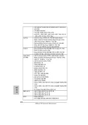
...; - IEEE 1394 헤더 1 LED 헤더 1 개 - LED 1 개 - GUI AMI UEFI 적합형 BIOS ASRock P67 Extreme6 Motherboard SATA3 6.0Gb/s 커넥터 2 RAID (RAID 0, RAID 1, RAID 10, RAID 5 및 Intel Rapid Storage), NCQ, AHCI &#...Storage NCQ, AHCI 6 개 의 SATA3 6.0Gb/s 1 1 개 - LED 1 개 - 64Mb AMI BIOS - LED 가 달린 CMOS 1 개 - 한 국 어 SATA3 USB 3.0 BIOS 214 - 2 개 LED(ACT/LINK LED 및 SPEED LED RJ-45 LAN 포트 - 1 개...
...; - IEEE 1394 헤더 1 LED 헤더 1 개 - LED 1 개 - GUI AMI UEFI 적합형 BIOS ASRock P67 Extreme6 Motherboard SATA3 6.0Gb/s 커넥터 2 RAID (RAID 0, RAID 1, RAID 10, RAID 5 및 Intel Rapid Storage), NCQ, AHCI &#...Storage NCQ, AHCI 6 개 의 SATA3 6.0Gb/s 1 1 개 - LED 1 개 - 64Mb AMI BIOS - LED 가 달린 CMOS 1 개 - 한 국 어 SATA3 USB 3.0 BIOS 214 - 2 개 LED(ACT/LINK LED 및 SPEED LED RJ-45 LAN 포트 - 1 개...
Quick Installation Guide
Page 226
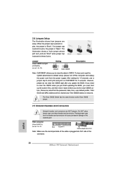
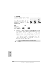
2.8 3 1-2 점퍼 CMOS 초기화 (CLRCMOS1, 3 2 32 세팅 CMOS 삭제 참고 : CLRCMOS1 CMOS 15 CLRCMOS1 의 핀 2 와 핀 3 을 5 BIOS CMOS BIOS CMOS CMOS CMOS 1394 GUID, MAC Clear CMOS Switch는 Clear CMOS 한 국 어 226 ASRock P67 Extreme6 Motherboard
2.8 3 1-2 점퍼 CMOS 초기화 (CLRCMOS1, 3 2 32 세팅 CMOS 삭제 참고 : CLRCMOS1 CMOS 15 CLRCMOS1 의 핀 2 와 핀 3 을 5 BIOS CMOS BIOS CMOS CMOS CMOS 1394 GUID, MAC Clear CMOS Switch는 Clear CMOS 한 국 어 226 ASRock P67 Extreme6 Motherboard
Quick Installation Guide
Page 242
BIOS 注意 1. 2. 3. 4. 5. 6. CD 68 Dual Channel Memory Technology 248 DDR3 K CPU の みが 2133 と 1866 への DDR3 Windows® 7 / VistaTM / XP 4GB 64 ビット CPU の Windows® OS 2 4 6 8 3 ASRock Extreme Tuning Utility (AXTU OC DNA、ES CPU OC DNA OC OC OC IES CPU ASRock Extreme Tuning Utility (AXTU Web ASRock Web サイト :http://www.asrock.com 日本語 242 ASRock P67 Extreme6 Motherboard
BIOS 注意 1. 2. 3. 4. 5. 6. CD 68 Dual Channel Memory Technology 248 DDR3 K CPU の みが 2133 と 1866 への DDR3 Windows® 7 / VistaTM / XP 4GB 64 ビット CPU の Windows® OS 2 4 6 8 3 ASRock Extreme Tuning Utility (AXTU OC DNA、ES CPU OC DNA OC OC OC IES CPU ASRock Extreme Tuning Utility (AXTU Web ASRock Web サイト :http://www.asrock.com 日本語 242 ASRock P67 Extreme6 Motherboard

Quick Installation Guide
Page 243
ASRock Instant Flash は、Flash ROM ROM BIOS BIOS より、MS-DOS Windows BIOS POST の間に 7.
ASRock Instant Flash は、Flash ROM ROM BIOS BIOS より、MS-DOS Windows BIOS POST の間に 7.
Quick Installation Guide
Page 252
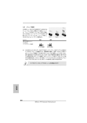
2.8 1-2 CMOS CLRCMOS1 32 参照) 設定 説明 CMOS の消去 注 : CLRCMOS1 CMOS 15 CLRCMOS1 のピン 2 とピン 3 を 5 BIOS CMOS BIOS CMOS CMOS 1394 GUID と MAC CMOS クリアCMOS CMOS 日本語 252 ASRock P67 Extreme6 Motherboard
2.8 1-2 CMOS CLRCMOS1 32 参照) 設定 説明 CMOS の消去 注 : CLRCMOS1 CMOS 15 CLRCMOS1 のピン 2 とピン 3 を 5 BIOS CMOS BIOS CMOS CMOS 1394 GUID と MAC CMOS クリアCMOS CMOS 日本語 252 ASRock P67 Extreme6 Motherboard


