RAID Installation Guide
Page 2
... 5, and Intel Matrix Storage. This section will guide you how to create RAID on this guide carefully according to the Intel southbridge chipset that your motherboard adopts. Please read the RAID configurations in the support CD. You may install SATA hard disks on SATA ports. 2 Guide to Serial ATA (SATA) Hard...
... 5, and Intel Matrix Storage. This section will guide you how to create RAID on this guide carefully according to the Intel southbridge chipset that your motherboard adopts. Please read the RAID configurations in the support CD. You may install SATA hard disks on SATA ports. 2 Guide to Serial ATA (SATA) Hard...
RAID Installation Guide
Page 3
... the surviving drive as a single drive but at a sustained data transfer rate. This section will direct all applications to RAID Configurations 2.1 Introduction of RAID This motherboard adopts Intel southbridge chipset that copies and maintains an identical image of the data in parallel, interleaved stacks. For optimal performance, please install identical drives...
... the surviving drive as a single drive but at a sustained data transfer rate. This section will direct all applications to RAID Configurations 2.1 Introduction of RAID This motherboard adopts Intel southbridge chipset that copies and maintains an identical image of the data in parallel, interleaved stacks. For optimal performance, please install identical drives...

RAID Installation Guide
Page 8
..." System to RAID 0, RAID 1 or RAID 5 If you have an existing "RAID Ready" system, then you will need another SATA / SATAII hard drive with your motherboard or after downloading it as the source hard drive. 1. If you install. Finish the Windows® installation and install all necessary drivers. 6. After setting up...
..." System to RAID 0, RAID 1 or RAID 5 If you have an existing "RAID Ready" system, then you will need another SATA / SATAII hard drive with your motherboard or after downloading it as the source hard drive. 1. If you install. Finish the Windows® installation and install all necessary drivers. 6. After setting up...
User Manual
Page 2
...incidental, or consequential damages (including damages for loss of profits, loss of business, loss of data, interruption of business and the like), even if ASRock has been advised of the possibility of their respective companies, and are furnished for informational use only and subject to change without intent to the... operation. "Perchlorate Material-special handling may not be constructed as a commitment by the California Legislature. Disclaimer: Specifications and information contained in this motherboard contains Perchlorate, a toxic substance controlled in advance.
...incidental, or consequential damages (including damages for loss of profits, loss of business, loss of data, interruption of business and the like), even if ASRock has been advised of the possibility of their respective companies, and are furnished for informational use only and subject to change without intent to the... operation. "Perchlorate Material-special handling may not be constructed as a commitment by the California Legislature. Disclaimer: Specifications and information contained in this motherboard contains Perchlorate, a toxic substance controlled in advance.
User Manual
Page 3
Contents 1 Introduction 5 1.1 Package Contents 5 1.2 Specifications 6 1.3 Two CrossFireXTM Graphics Card Support List 10 1.4 Motherboard Layout 11 1.5 I/O Panel 12 2 Installation 14 2.1 Screw Holes 14 2.2 Pre-installation Precautions 14 2.3 CPU Installation 15 2.4 Installation of Heatsink and CPU fan 17 2.5 Installation of ...
Contents 1 Introduction 5 1.1 Package Contents 5 1.2 Specifications 6 1.3 Two CrossFireXTM Graphics Card Support List 10 1.4 Motherboard Layout 11 1.5 I/O Panel 12 2 Installation 14 2.1 Screw Holes 14 2.2 Pre-installation Precautions 14 2.3 CPU Installation 15 2.4 Installation of Heatsink and CPU fan 17 2.5 Installation of ...

User Manual
Page 5
... the content of the Support CD. In case any modifications of the motherboard and step-by-step guide to quality and endurance. www.asrock.com/support/index.asp 1.1 Package Contents ASRock P55M Pro Motherboard (Micro ATX Form Factor: 9.6-in x 8.8-in Floppy Drive 2 x...in , 24.4 cm x 22.4 cm) ASRock P55M Pro Quick Installation Guide ASRock P55M Pro Support CD 1 x 80-conductor Ultra ATA 66/100/133 IDE Ribbon Cable 1 x Ribbon Cable for purchasing ASRock P55M Pro motherboard, a reliable motherboard produced under ASRock's consistently stringent quality control. It delivers excellent ...
... the content of the Support CD. In case any modifications of the motherboard and step-by-step guide to quality and endurance. www.asrock.com/support/index.asp 1.1 Package Contents ASRock P55M Pro Motherboard (Micro ATX Form Factor: 9.6-in x 8.8-in Floppy Drive 2 x...in , 24.4 cm x 22.4 cm) ASRock P55M Pro Quick Installation Guide ASRock P55M Pro Support CD 1 x 80-conductor Ultra ATA 66/100/133 IDE Ribbon Cable 1 x Ribbon Cable for purchasing ASRock P55M Pro motherboard, a reliable motherboard produced under ASRock's consistently stringent quality control. It delivers excellent ...
User Manual
Page 8
...page 12 for details. 3. Please check the table on page 43 for proper connection. 7. ASRock website: http://www.asrock.com/feature/OCTuner/index.htm 8 CAUTION! 1. About the setting of ASRock OC Tuner. For Windows® XP 64-bit and Windows® VistaTM 64-bit with...of "Hyper Threading Technology", please check page 50. 2. Voltage Monitoring: +12V, +5V, +3.3V, CPU Vcore OS - For microphone input, this motherboard supports 2-channel, 4channel, 6-channel, and 8-channel modes. Please visit our website for proper installation. 4. FCC, CE, WHQL - It should be ...
...page 12 for details. 3. Please check the table on page 43 for proper connection. 7. ASRock website: http://www.asrock.com/feature/OCTuner/index.htm 8 CAUTION! 1. About the setting of ASRock OC Tuner. For Windows® XP 64-bit and Windows® VistaTM 64-bit with...of "Hyper Threading Technology", please check page 50. 2. Voltage Monitoring: +12V, +5V, +3.3V, CPU Vcore OS - For microphone input, this motherboard supports 2-channel, 4channel, 6-channel, and 8-channel modes. Please visit our website for proper installation. 4. FCC, CE, WHQL - It should be ...
User Manual
Page 9
... a revolutionary technology that the USB flash drive or hard drive must meet EuP standard, an EuP ready motherboard and an EuP ready power supply are required. ASRock website: http://www.asrock.com/feature/IES/index.html 11. Frequencies other words, it is a BIOS flash utility embedded in a...00W in off mode condition. With this utility, you can load the OC profile to their own system to access ASRock Instant Flash. Just launch this motherboard offers stepless control, it is higher than the recommended CPU bus frequencies may cause the instability of 5v standby power ...
... a revolutionary technology that the USB flash drive or hard drive must meet EuP standard, an EuP ready motherboard and an EuP ready power supply are required. ASRock website: http://www.asrock.com/feature/IES/index.html 11. Frequencies other words, it is a BIOS flash utility embedded in a...00W in off mode condition. With this utility, you can load the OC profile to their own system to access ASRock Instant Flash. Just launch this motherboard offers stepless control, it is higher than the recommended CPU bus frequencies may cause the instability of 5v standby power ...
User Manual
Page 14
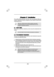
...! Hold components by circles to secure the motherboard to unplug the power cord before you install motherboard components or change any component, place it . Doing so may damage the motherboard. 2.2 Pre-installation Precautions Take note of your motherboard directly on a grounded antistatic pad or in..., ensure that the power is switched off or the power cord is a Micro ATX form factor (9.6" x 8.8", 24.4 x 22.4 cm) motherboard. Chapter 2: Installation This is detached from the wall socket before you handle components. 3. Failure to do so may cause severe damage to use...
...! Hold components by circles to secure the motherboard to unplug the power cord before you install motherboard components or change any component, place it . Doing so may damage the motherboard. 2.2 Pre-installation Precautions Take note of your motherboard directly on a grounded antistatic pad or in..., ensure that the power is switched off or the power cord is a Micro ATX form factor (9.6" x 8.8", 24.4 x 22.4 cm) motherboard. Chapter 2: Installation This is detached from the wall socket before you handle components. 3. Failure to do so may cause severe damage to use...
User Manual
Page 15
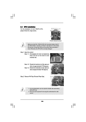
... approximately 135 degrees. Rotate the load lever to handle and avoid kicking off the PnP cap. 2. Otherwise, the CPU will be placed if returning the motherboard for after service. 15 Disengaging the lever by depressing down and out on the socket. Rotate the load plate to clear retention tab. 2.3 CPU Installation...
... approximately 135 degrees. Rotate the load lever to handle and avoid kicking off the PnP cap. 2. Otherwise, the CPU will be placed if returning the motherboard for after service. 15 Disengaging the lever by depressing down and out on the socket. Rotate the load plate to clear retention tab. 2.3 CPU Installation...

User Manual
Page 17
... are securely fastened and in good contact with remaining fasteners. Step 4. Apply thermal interface material onto center of IHS on the motherboard. For proper installation, please kindly refer to illustrate the installation of the heatsink for Socket LGA 1156 CPU fan. 17 Below...contact other . Rotate the fastener clockwise, then press down the fasteners without rotating them clockwise, the heatsink cannot be noticed that this motherboard supports Combo Cooler Option (C.C.O.), which provides the flexible option to install and lock. Step 6. Secure excess cable with tie-wrap to...
... are securely fastened and in good contact with remaining fasteners. Step 4. Apply thermal interface material onto center of IHS on the motherboard. For proper installation, please kindly refer to illustrate the installation of the heatsink for Socket LGA 1156 CPU fan. 17 Below...contact other . Rotate the fastener clockwise, then press down the fasteners without rotating them clockwise, the heatsink cannot be noticed that this motherboard supports Combo Cooler Option (C.C.O.), which provides the flexible option to install and lock. Step 6. Secure excess cable with tie-wrap to...
User Manual
Page 18
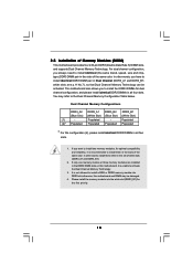
... (Blue Slot) (White Slot) (1) - If only one memory module or three memory modules are installed in the slots of Memory Modules (DIMM) This motherboard provides four 240-pin DDR3 (Double Data Rate 3) DIMM slots, and supports Dual Channel Memory Technology. In other words, install them in the DDR3 DIMM... slots on this motherboard, it is recommended to install identical (the same brand, speed, size and chiptype) DDR3 DIMM pair in the slots of white slots (DDR3_A1 ...
... (Blue Slot) (White Slot) (1) - If only one memory module or three memory modules are installed in the slots of Memory Modules (DIMM) This motherboard provides four 240-pin DDR3 (Double Data Rate 3) DIMM slots, and supports Dual Channel Memory Technology. In other words, install them in the DDR3 DIMM... slots on this motherboard, it is recommended to install identical (the same brand, speed, size and chiptype) DDR3 DIMM pair in the slots of white slots (DDR3_A1 ...
User Manual
Page 19
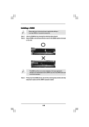
... fully snap back in one correct orientation. Step 1. Unlock a DIMM slot by pressing the retaining clips outward. Step 2. Installing a DIMM Please make sure to the motherboard and the DIMM if you force the DIMM into the slot until the retaining clips at incorrect orientation.
... fully snap back in one correct orientation. Step 1. Unlock a DIMM slot by pressing the retaining clips outward. Step 2. Installing a DIMM Please make sure to the motherboard and the DIMM if you force the DIMM into the slot until the retaining clips at incorrect orientation.
User Manual
Page 20
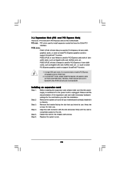
PCIE slots: PCIE1 (PCIE x16 slot; PCIE3 (PCIE x16 slot; In CrossFireXTM mode, please install PCI Express x16 graphics cards on this motherboard. Step 2. Remove the system unit cover (if your motherboard is unplugged. Remove the bracket facing the slot that you start the installation. Keep the screws for PCI Express x1 lane...
PCIE slots: PCIE1 (PCIE x16 slot; PCIE3 (PCIE x16 slot; In CrossFireXTM mode, please install PCI Express x16 graphics cards on this motherboard. Step 2. Remove the system unit cover (if your motherboard is unplugged. Remove the bracket facing the slot that you start the installation. Keep the screws for PCI Express x1 lane...
User Manual
Page 21
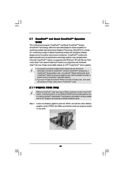
...1. Make sure that ATITM has released or will release in any 3D application. 2.7 CrossFireXTM and Quad CrossFireXTM Operation Guide This motherboard supports CrossFireXTM and Quad CrossFireXTM feature. In below procedures, we use Radeon HD 3870 as 12-pipe cards while in a ... Windows® XP with Windows® VistaTM OS only. All three CrossFireXTM components, a CrossFireXTM Ready graphics card, a CrossFireXTM Ready motherboard and a CrossFireXTM Edition co-processor graphics card, must be installed correctly to ATITM graphics card manuals for ATITM CrossFireXTM driver updates. 1....
...1. Make sure that ATITM has released or will release in any 3D application. 2.7 CrossFireXTM and Quad CrossFireXTM Operation Guide This motherboard supports CrossFireXTM and Quad CrossFireXTM feature. In below procedures, we use Radeon HD 3870 as 12-pipe cards while in a ... Windows® XP with Windows® VistaTM OS only. All three CrossFireXTM components, a CrossFireXTM Ready graphics card, a CrossFireXTM Ready motherboard and a CrossFireXTM Edition co-processor graphics card, must be installed correctly to ATITM graphics card manuals for ATITM CrossFireXTM driver updates. 1....

User Manual
Page 22
... the Radeon graphics card on the top of Radeon graphics cards. (CrossFire Bridge is provided with the graphics card you purchase, not bundled with this motherboard. Connect two Radeon graphics cards by installing CrossFire Bridge on CrossFire Bridge Interconnects on PCIE1 slot. (You may use the DVI to D-Sub adapter to...
... the Radeon graphics card on the top of Radeon graphics cards. (CrossFire Bridge is provided with the graphics card you purchase, not bundled with this motherboard. Connect two Radeon graphics cards by installing CrossFire Bridge on CrossFire Bridge Interconnects on PCIE1 slot. (You may use the DVI to D-Sub adapter to...
User Manual
Page 25
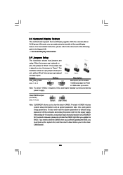
... setup parameters. If you to default setup, please turn off the computer and unplug the power cord from the power supply. 2.8 Surround Display Feature This motherboard supports Surround Display upgrade.
... setup parameters. If you to default setup, please turn off the computer and unplug the power cord from the power supply. 2.8 Surround Display Feature This motherboard supports Surround Display upgrade.
User Manual
Page 26
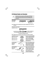
... permanent damage of the power supply. The current SATAII interface allows up to the power connector on this motherboard. Then connect the white end of SATA power cable to the power connector of the motherboard! Serial ATAII Connectors (SATAII_1: see p.11, No. 11) (SATAII_2: see p.11, No. 10) (SATAII_3: ... the SATAII connector on each drive. FDD connector (33-pin FLOPPY1) (see p.11 No. 9) PIN1 IDE1 connect the blue end to the motherboard connect the black end to the IDE devices 80-conductor ATA 66/100/133 cable Note: Please refer to the instruction of SATA power cable...
... permanent damage of the power supply. The current SATAII interface allows up to the power connector on this motherboard. Then connect the white end of SATA power cable to the power connector of the motherboard! Serial ATAII Connectors (SATAII_1: see p.11, No. 11) (SATAII_2: see p.11, No. 10) (SATAII_3: ... the SATAII connector on each drive. FDD connector (33-pin FLOPPY1) (see p.11 No. 9) PIN1 IDE1 connect the blue end to the motherboard connect the black end to the IDE devices 80-conductor ATA 66/100/133 cable Note: Please refer to the instruction of SATA power cable...
User Manual
Page 27
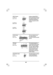
...# SPD5 BUSY SPD4 PE SPD3 SLCT SPD2 SPD1 SPD0 STB# Besides six default USB 2.0 ports on the I/O panel, there are three USB 2.0 headers on this motherboard. Each USB 2.0 header can securely store keys, digital certificates, passwords, and data. USB 2.0 Headers (9-pin USB12_13) (see p.11 No. 16) USB_PWR P-13 P+13 GND DUMMY...
...# SPD5 BUSY SPD4 PE SPD3 SLCT SPD2 SPD1 SPD0 STB# Besides six default USB 2.0 ports on the I/O panel, there are three USB 2.0 headers on this motherboard. Each USB 2.0 header can securely store keys, digital certificates, passwords, and data. USB 2.0 Headers (9-pin USB12_13) (see p.11 No. 16) USB_PWR P-13 P+13 GND DUMMY...
User Manual
Page 29
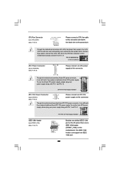
...ATX Power Connector (24-pin ATXPWR1) (see p.11, No. 8) 12 24 Please connect an ATX power supply to this connector. 1 13 Though this motherboard provides 4-Pin CPU fan (Quiet Fan) support, the 3-Pin CPU fan still can work if you adopt a traditional 20-pin ATX power supply. This ...IEEE 1394 header can support one IEEE 1394 header (FRONT_1394) on this motherboard. Though this motherboard provides 24-pin ATX power connector, 12 24 it can still work successfully even without the fan speed control function. To use the 4-...
...ATX Power Connector (24-pin ATXPWR1) (see p.11, No. 8) 12 24 Please connect an ATX power supply to this connector. 1 13 Though this motherboard provides 4-Pin CPU fan (Quiet Fan) support, the 3-Pin CPU fan still can work if you adopt a traditional 20-pin ATX power supply. This ...IEEE 1394 header can support one IEEE 1394 header (FRONT_1394) on this motherboard. Though this motherboard provides 24-pin ATX power connector, 12 24 it can still work successfully even without the fan speed control function. To use the 4-...

