RAID Installation Guide
Page 2
... guide you how to create RAID on this guide carefully according to the Intel southbridge chipset that your motherboard adopts. Guide to Serial ATA (SATA) Hard Disks Installation of "User Manual" in this motherboard for internal storage devices. For SATA installation guide, please refer to SATA Hard Disks Installation 1.1 Serial ATA (SATA...
... guide you how to create RAID on this guide carefully according to the Intel southbridge chipset that your motherboard adopts. Guide to Serial ATA (SATA) Hard Disks Installation of "User Manual" in this motherboard for internal storage devices. For SATA installation guide, please refer to SATA Hard Disks Installation 1.1 Serial ATA (SATA...
RAID Installation Guide
Page 3
... drive to a second drive. It will improve data access and storage since the disk array management software will introduce the basic knowledge of RAID This motherboard adopts Intel southbridge chipset that integrates RAID controller supporting RAID 0 / RAID 1/ Intel Matrix Storage / RAID 10 / RAID 5 function with six independent Serial ATA (SATA) channels...
... drive to a second drive. It will improve data access and storage since the disk array management software will introduce the basic knowledge of RAID This motherboard adopts Intel southbridge chipset that integrates RAID controller supporting RAID 0 / RAID 1/ Intel Matrix Storage / RAID 10 / RAID 5 function with six independent Serial ATA (SATA) channels...

RAID Installation Guide
Page 8
... may select: "Intel(R) ICH8R/ICH9R/ICH10R/DO/PCH SATA RAID Controller - It's important to understand what will need another SATA / SATAII hard drive with your motherboard or after downloading it as the source hard drive when initiating the migration. 2. Select the driver to install according to the mode you choose and...
... may select: "Intel(R) ICH8R/ICH9R/ICH10R/DO/PCH SATA RAID Controller - It's important to understand what will need another SATA / SATAII hard drive with your motherboard or after downloading it as the source hard drive when initiating the migration. 2. Select the driver to install according to the mode you choose and...
User Manual
Page 2
...the Lithium battery in California, USA, please follow the related regulations in Perchlorate Best Management Practices (BMP) regulations passed by ASRock. Products and corporate names appearing in the manual or product. Disclaimer: Specifications and information contained in this manual may or may... not cause harmful interference, and (2) this motherboard contains Perchlorate, a toxic substance controlled in advance. In no responsibility for any errors or omissions that may apply, see ...
...the Lithium battery in California, USA, please follow the related regulations in Perchlorate Best Management Practices (BMP) regulations passed by ASRock. Products and corporate names appearing in the manual or product. Disclaimer: Specifications and information contained in this manual may or may... not cause harmful interference, and (2) this motherboard contains Perchlorate, a toxic substance controlled in advance. In no responsibility for any errors or omissions that may apply, see ...
User Manual
Page 3
Contents 1 Introduction 5 1.1 Package Contents 5 1.2 Specifications 6 1.3 Two CrossFireXTM Graphics Card Support List 10 1.4 Motherboard Layout 11 1.5 I/O Panel 12 2 Installation 14 2.1 Screw Holes 14 2.2 Pre-installation Precautions 14 2.3 CPU Installation 15 2.4 Installation of Heatsink and CPU fan 17 2.5 Installation of ...
Contents 1 Introduction 5 1.1 Package Contents 5 1.2 Specifications 6 1.3 Two CrossFireXTM Graphics Card Support List 10 1.4 Motherboard Layout 11 1.5 I/O Panel 12 2 Installation 14 2.1 Screw Holes 14 2.2 Pre-installation Precautions 14 2.3 CPU Installation 15 2.4 Installation of Heatsink and CPU fan 17 2.5 Installation of ...

User Manual
Page 5
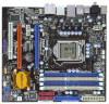
...Ultra ATA 66/100/133 IDE Ribbon Cable 1 x Ribbon Cable for specific information about the model you are using. www.asrock.com/support/index.asp 1.1 Package Contents ASRock P55M Pro Motherboard (Micro ATX Form Factor: 9.6-in x 8.8-in Floppy Drive 2 x Serial ATA (SATA) Data Cables (Optional) 1 ...may find the latest VGA cards and CPU support lists on ASRock website without notice. ASRock website http://www.asrock.com If you for purchasing ASRock P55M Pro motherboard, a reliable motherboard produced under ASRock's consistently stringent quality control. Chapter 1: Introduction Thank you ...
...Ultra ATA 66/100/133 IDE Ribbon Cable 1 x Ribbon Cable for specific information about the model you are using. www.asrock.com/support/index.asp 1.1 Package Contents ASRock P55M Pro Motherboard (Micro ATX Form Factor: 9.6-in x 8.8-in Floppy Drive 2 x Serial ATA (SATA) Data Cables (Optional) 1 ...may find the latest VGA cards and CPU support lists on ASRock website without notice. ASRock website http://www.asrock.com If you for purchasing ASRock P55M Pro motherboard, a reliable motherboard produced under ASRock's consistently stringent quality control. Chapter 1: Introduction Thank you ...
User Manual
Page 8
... the "SATAII Hard Disk Setup Guide" on page 12 for USB 2.0 works fine under Windows® environment. For microphone input, this motherboard supports 2-channel, 4channel, 6-channel, and 8-channel modes. - EuP Ready (EuP ready power supply is required) (see CAUTION 16) ...detailed product information, please visit our website: http://www.asrock.com WARNING Please realize that only support up to SATAII connector, please read "Untied Overclocking Technology" on page 18 for details. 3. This motherboard supports Untied Overclocking Technology. Before you to get the ...
... the "SATAII Hard Disk Setup Guide" on page 12 for USB 2.0 works fine under Windows® environment. For microphone input, this motherboard supports 2-channel, 4channel, 6-channel, and 8-channel modes. - EuP Ready (EuP ready power supply is required) (see CAUTION 16) ...detailed product information, please visit our website: http://www.asrock.com WARNING Please realize that only support up to SATAII connector, please read "Untied Overclocking Technology" on page 18 for details. 3. This motherboard supports Untied Overclocking Technology. Before you to get the ...
User Manual
Page 9
...it is capable of overclocking settings. With OC DNA, you resume the system, please check if the CPU fan on the same motherboard. 13. While CPU overheat is higher than the recommended CPU bus frequencies may cause the instability of Intelligent Energy Saver. Please visit...system to record the OC settings and share with others. 10. ASRock website: http://www.asrock.com/feature/IES/index.html 11. This convenient BIOS update tool allows you what it back again. With this motherboard offers stepless control, it is a revolutionary technology that delivers unparalleled ...
...it is capable of overclocking settings. With OC DNA, you resume the system, please check if the CPU fan on the same motherboard. 13. While CPU overheat is higher than the recommended CPU bus frequencies may cause the instability of Intelligent Energy Saver. Please visit...system to record the OC settings and share with others. 10. ASRock website: http://www.asrock.com/feature/IES/index.html 11. This convenient BIOS update tool allows you what it back again. With this motherboard offers stepless control, it is a revolutionary technology that delivers unparalleled ...
User Manual
Page 14
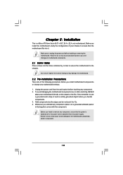
.... 2. Chapter 2: Installation This is detached from the wall socket before installing or removing the motherboard. Doing so may damage the motherboard. 2.2 Pre-installation Precautions Take note of your motherboard directly on a grounded antistatic pad or in the bag that comes with the component. Failure ...is switched off or the power cord is a Micro ATX form factor (9.6" x 8.8", 24.4 x 22.4 cm) motherboard. Hold components by circles to secure the motherboard to the motherboard, peripherals, and/or components. 14 Do not over-tighten the screws! Failure to do not touch the ICs. 4....
.... 2. Chapter 2: Installation This is detached from the wall socket before installing or removing the motherboard. Doing so may damage the motherboard. 2.2 Pre-installation Precautions Take note of your motherboard directly on a grounded antistatic pad or in the bag that comes with the component. Failure ...is switched off or the power cord is a Micro ATX form factor (9.6" x 8.8", 24.4 x 22.4 cm) motherboard. Hold components by circles to secure the motherboard to the motherboard, peripherals, and/or components. 14 Do not over-tighten the screws! Failure to do not touch the ICs. 4....
User Manual
Page 15
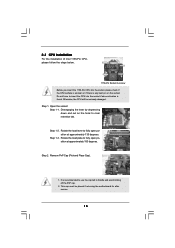
... and avoid kicking off the PnP cap. 2. Step 1. Step 1-3. Remove PnP Cap (Pick and Place Cap). 1. Otherwise, the CPU will be placed if returning the motherboard for after service. 15 Rotate the load plate to fully open position at approximately 100 degrees. Step 2. This cap must be seriously damaged. Open the...
... and avoid kicking off the PnP cap. 2. Step 1. Step 1-3. Remove PnP Cap (Pick and Place Cap). 1. Otherwise, the CPU will be placed if returning the motherboard for after service. 15 Rotate the load plate to fully open position at approximately 100 degrees. Step 2. This cap must be seriously damaged. Open the...

User Manual
Page 17
... are securely fastened and in good contact with 1156-Pin socket that supports Intel 1156-Pin CPU. Fan cables on fastener caps with the motherboard throughholes. Step 6. Then connect the CPU fan to the CPU_FAN connector (CPU_FAN1, see page 11, No. 3). Step 5. Connect fan header... with remaining fasteners. Ensure that this motherboard supports Combo Cooler Option (C.C.O.), which provides the flexible option to adopt two different CPU cooler types, Socket LGA 775 and LGA 1156. Ensure fan...
... are securely fastened and in good contact with 1156-Pin socket that supports Intel 1156-Pin CPU. Fan cables on fastener caps with the motherboard throughholes. Step 6. Then connect the CPU fan to the CPU_FAN connector (CPU_FAN1, see page 11, No. 3). Step 5. Connect fan header... with remaining fasteners. Ensure that this motherboard supports Combo Cooler Option (C.C.O.), which provides the flexible option to adopt two different CPU cooler types, Socket LGA 775 and LGA 1156. Ensure fan...
User Manual
Page 18
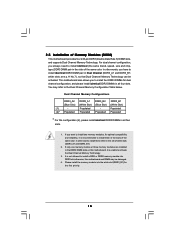
... Configuration Table below. Populated - If only one memory module or three memory modules are installed in the DDR3 DIMM slots on this motherboard and DIMM may refer to install identical (the same brand, speed, size and chiptype) DDR3 DIMM pair in all four slots. white...; Populated (2)* Populated Populated Populated Populated * For the configuration (2), please install identical DDR3 DIMMs in the slots of Memory Modules (DIMM) This motherboard provides four 240-pin DDR3 (Double Data Rate 3) DIMM slots, and supports Dual Channel Memory Technology. It is not allowed to install a ...
... Configuration Table below. Populated - If only one memory module or three memory modules are installed in the DDR3 DIMM slots on this motherboard and DIMM may refer to install identical (the same brand, speed, size and chiptype) DDR3 DIMM pair in all four slots. white...; Populated (2)* Populated Populated Populated Populated * For the configuration (2), please install identical DDR3 DIMMs in the slots of Memory Modules (DIMM) This motherboard provides four 240-pin DDR3 (Double Data Rate 3) DIMM slots, and supports Dual Channel Memory Technology. It is not allowed to install a ...
User Manual
Page 19
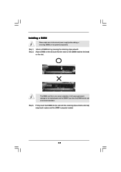
Installing a DIMM Please make sure to the motherboard and the DIMM if you force the DIMM into the slot until the retaining clips at incorrect orientation. Step 2. Step 1. Align a DIMM on the slot ...
Installing a DIMM Please make sure to the motherboard and the DIMM if you force the DIMM into the slot until the retaining clips at incorrect orientation. Step 2. Step 1. Align a DIMM on the slot ...
User Manual
Page 20
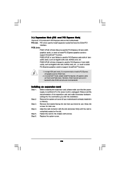
...used to install PCI Express graphics cards to support CrossFireXTM function. 1. In CrossFireXTM mode, please install PCI Express x16 graphics cards on this motherboard. Please read the documentation of the expansion card and make sure that the power supply is switched off or the power cord is used...or used to install PCI Express graphics cards to install a PCI Express x16 graphics card on the slot. Remove the system unit cover (if your motherboard is completely seated on PCIE1 slot. 2. Step 4. Step 6. Therefore, PCIE1 slot will work at x16 bandwidth while PCIE3 slot will work at ...
...used to install PCI Express graphics cards to support CrossFireXTM function. 1. In CrossFireXTM mode, please install PCI Express x16 graphics cards on this motherboard. Please read the documentation of the expansion card and make sure that the power supply is switched off or the power cord is used...or used to install PCI Express graphics cards to install a PCI Express x16 graphics card on the slot. Remove the system unit cover (if your motherboard is completely seated on PCIE1 slot. 2. Step 4. Step 6. Therefore, PCIE1 slot will work at x16 bandwidth while PCIE3 slot will work at ...
User Manual
Page 21
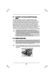
All three CrossFireXTM components, a CrossFireXTM Ready graphics card, a CrossFireXTM Ready motherboard and a CrossFireXTM Edition co-processor graphics card, must be installed correctly to PCIE3 slot. Insert one Radeon graphics card into PCIE1 slot and ... Graphics Processing Units (GPU) in any 3D application. Please check AMD website for detailed installation guide. 2.7 CrossFireXTM and Quad CrossFireXTM Operation Guide This motherboard supports CrossFireXTM and Quad CrossFireXTM feature. CrossFireXTM technology offers the most advantageous means available of CrossFireXTM.
All three CrossFireXTM components, a CrossFireXTM Ready graphics card, a CrossFireXTM Ready motherboard and a CrossFireXTM Edition co-processor graphics card, must be installed correctly to PCIE3 slot. Insert one Radeon graphics card into PCIE1 slot and ... Graphics Processing Units (GPU) in any 3D application. Please check AMD website for detailed installation guide. 2.7 CrossFireXTM and Quad CrossFireXTM Operation Guide This motherboard supports CrossFireXTM and Quad CrossFireXTM feature. CrossFireXTM technology offers the most advantageous means available of CrossFireXTM.

User Manual
Page 22
... the Radeon graphics card on the top of Radeon graphics cards. (CrossFire Bridge is provided with the graphics card you purchase, not bundled with this motherboard. Step 2.
... the Radeon graphics card on the top of Radeon graphics cards. (CrossFire Bridge is provided with the graphics card you purchase, not bundled with this motherboard. Step 2.
User Manual
Page 25
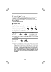
... detailed instruction, please refer to default setup, please turn off the computer and unplug the power cord from the power supply. 2.8 Surround Display Feature This motherboard supports Surround Display upgrade.
... detailed instruction, please refer to default setup, please turn off the computer and unplug the power cord from the power supply. 2.8 Surround Display Feature This motherboard supports Surround Display upgrade.
User Manual
Page 26
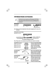
...the white end of SATA power cable to the power connector of the SATA data cable can be connected to the power connector on this motherboard. FDD connector (33-pin FLOPPY1) (see p.11, No. 13) SATAII_4 SATAII_2 SATAII_3 SATAII_1 These four Serial ATAII (SATAII) connectors ...support SATA data cables for the details. Please connect the black end of the motherboard! Placing jumper caps over these headers and connectors. Do NOT place jumper caps over the headers and connectors will cause permanent damage of...
...the white end of SATA power cable to the power connector of the SATA data cable can be connected to the power connector on this motherboard. FDD connector (33-pin FLOPPY1) (see p.11, No. 13) SATAII_4 SATAII_2 SATAII_3 SATAII_1 These four Serial ATAII (SATAII) connectors ...support SATA data cables for the details. Please connect the black end of the motherboard! Placing jumper caps over these headers and connectors. Do NOT place jumper caps over the headers and connectors will cause permanent damage of...
User Manual
Page 27
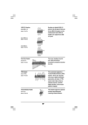
...# SPD5 BUSY SPD4 PE SPD3 SLCT SPD2 SPD1 SPD0 STB# Besides six default USB 2.0 ports on the I/O panel, there are three USB 2.0 headers on this motherboard. A TPM system also helps enhance network security, protects digital identities, and ensures platform integrity. Each USB 2.0 header can securely store keys, digital certificates, passwords, and...
...# SPD5 BUSY SPD4 PE SPD3 SLCT SPD2 SPD1 SPD0 STB# Besides six default USB 2.0 ports on the I/O panel, there are three USB 2.0 headers on this motherboard. A TPM system also helps enhance network security, protects digital identities, and ensures platform integrity. Each USB 2.0 header can securely store keys, digital certificates, passwords, and...
User Manual
Page 29
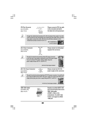
... Power Supply Installation 1 13 ATX 12V Power Connector (8-pin ATX12V1) (see p.11, No. 8) 12 24 Please connect an ATX power supply to this motherboard provides 4-Pin CPU fan (Quiet Fan) support, the 3-Pin CPU fan still can still work if you adopt a traditional 20-pin ATX power supply. ...Fan Installation ATX Power Connector (24-pin ATXPWR1) (see p.11 No. 2) 4 8 1 6 Please connect an ATX 12V power supply to this connector. 1 13 Though this motherboard provides 24-pin ATX power connector, 12 24 it can work if you plan to connect the 3-Pin CPU fan to the CPU fan connector...
... Power Supply Installation 1 13 ATX 12V Power Connector (8-pin ATX12V1) (see p.11, No. 8) 12 24 Please connect an ATX power supply to this motherboard provides 4-Pin CPU fan (Quiet Fan) support, the 3-Pin CPU fan still can still work if you adopt a traditional 20-pin ATX power supply. ...Fan Installation ATX Power Connector (24-pin ATXPWR1) (see p.11 No. 2) 4 8 1 6 Please connect an ATX 12V power supply to this connector. 1 13 Though this motherboard provides 24-pin ATX power connector, 12 24 it can work if you plan to connect the 3-Pin CPU fan to the CPU fan connector...

