User Manual
Page 9
... the OC profile to their own system to adopt two different CPU cooler types, Socket LGA 775 and LGA 1156. EuP, stands for Energy Using Product, was a provision regulated by ASRock, provides a convenient way for the user to access ASRock Instant Flash. Your friends then can save your BIOS only in a few clicks without...
... the OC profile to their own system to adopt two different CPU cooler types, Socket LGA 775 and LGA 1156. EuP, stands for Energy Using Product, was a provision regulated by ASRock, provides a convenient way for the user to access ASRock Instant Flash. Your friends then can save your BIOS only in a few clicks without...
User Manual
Page 15
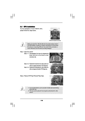
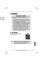
...the hook to fully open position at approximately 135 degrees. Step 1-3. Load Plate Load Lever Contact Array Socket Body 1156-Pin Socket Overview Before you insert the 1156-Pin CPU into the socket if above situation is recommended to use the cap tab to fully open position at approximately 100 degrees...., the CPU will be placed if returning the motherboard for after service. 15 2.3 CPU Installation For the installation of Intel 1156-Pin CPU, please follow the steps below. Open the socket: Step 1-1. Rotate the load plate to handle and avoid kicking off the PnP cap. 2.
...the hook to fully open position at approximately 135 degrees. Step 1-3. Load Plate Load Lever Contact Array Socket Body 1156-Pin Socket Overview Before you insert the 1156-Pin CPU into the socket if above situation is recommended to use the cap tab to fully open position at approximately 100 degrees...., the CPU will be placed if returning the motherboard for after service. 15 2.3 CPU Installation For the installation of Intel 1156-Pin CPU, please follow the steps below. Open the socket: Step 1-1. Rotate the load plate to handle and avoid kicking off the PnP cap. 2.

User Manual
Page 16
... Step 3-2. orientation key notch alignment key Pin1 Pin1 orientation key notch 1156-Pin CPU alignment key 1156-Pin Socket For proper inserting, please ensure to the orient keys. Carefully place the CPU into the socket by the edge where is within the socket and properly mated to match the two orientation key notches of the...
... Step 3-2. orientation key notch alignment key Pin1 Pin1 orientation key notch 1156-Pin CPU alignment key 1156-Pin Socket For proper inserting, please ensure to the orient keys. Carefully place the CPU into the socket by the edge where is within the socket and properly mated to match the two orientation key notches of the...

User Manual
Page 17
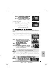
... motherboard is an example to illustrate the installation of the heatsink for Socket LGA 1156 CPU fan. 17 Ensure that the CPU and the heatsink are securely fastened and in good contact with 1156-Pin socket that this motherboard supports Combo Cooler Option (C.C.O.), which provides the flexible... (4 Places) If you need to spray thermal interface material between the CPU and the heatsink to adopt two different CPU cooler types, Socket LGA 775 and LGA 1156. Step 3. Step 4. Step 6. The white throughholes are oriented on side closest to the CPU_FAN connector (CPU_FAN1, see page 11, No...
... motherboard is an example to illustrate the installation of the heatsink for Socket LGA 1156 CPU fan. 17 Ensure that the CPU and the heatsink are securely fastened and in good contact with 1156-Pin socket that this motherboard supports Combo Cooler Option (C.C.O.), which provides the flexible... (4 Places) If you need to spray thermal interface material between the CPU and the heatsink to adopt two different CPU cooler types, Socket LGA 775 and LGA 1156. Step 3. Step 4. Step 6. The white throughholes are oriented on side closest to the CPU_FAN connector (CPU_FAN1, see page 11, No...
Quick Installation Guide
Page 2
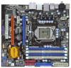
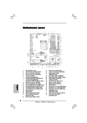
...) 2 ATX 12V Power Connector (ATX12V1) 20 Chassis Fan Connector (CHA_FAN1) 3 CPU Fan Connector (CPU_FAN1) 21 Chassis Speaker Header 4 Power Fan Connector (PWR_FAN1) (SPEAKER 1, Purple) 5 1156-Pin CPU Socket 22 Clear CMOS Jumper (CLRCMOS1) 6 2 x 240-pin DDR3 DIMM Slots 23 System Panel Header (PANEL1, Orange) (Dual Channel: DDR3_A2, DDR3_B2, Blue) 24 Infrared Module... Internal Audio Connector: CD1 (Black) 17 Front Panel IEEE 1394 Header 35 Front Panel Audio Header (FRONT_1394, Red) (HD_AUDIO1, Lime) 18 USB 2.0 Header (USB10_11, Blue) 2 ASRock P55M Pro Motherboard
...) 2 ATX 12V Power Connector (ATX12V1) 20 Chassis Fan Connector (CHA_FAN1) 3 CPU Fan Connector (CPU_FAN1) 21 Chassis Speaker Header 4 Power Fan Connector (PWR_FAN1) (SPEAKER 1, Purple) 5 1156-Pin CPU Socket 22 Clear CMOS Jumper (CLRCMOS1) 6 2 x 240-pin DDR3 DIMM Slots 23 System Panel Header (PANEL1, Orange) (Dual Channel: DDR3_A2, DDR3_B2, Blue) 24 Infrared Module... Internal Audio Connector: CD1 (Black) 17 Front Panel IEEE 1394 Header 35 Front Panel Audio Header (FRONT_1394, Red) (HD_AUDIO1, Lime) 18 USB 2.0 Header (USB10_11, Blue) 2 ASRock P55M Pro Motherboard
Quick Installation Guide
Page 9
... 1.00W in off mode condition. Although this motherboard offers stepless control, it is able to adopt two different CPU cooler types, Socket LGA 775 and LGA 1156. To improve heat dissipation, remember to get the same OC settings as a profile and share with your BIOS only in Flash ...Your friends then can press key during the POST or press key to BIOS setup menu to define the power consumption for more details. 9 ASRock P55M Pro Motherboard English According to Intel's suggestion, the EuP ready power supply must use FAT32/16/12 file system. 12. Please be noticed that...
... 1.00W in off mode condition. Although this motherboard offers stepless control, it is able to adopt two different CPU cooler types, Socket LGA 775 and LGA 1156. To improve heat dissipation, remember to get the same OC settings as a profile and share with your BIOS only in Flash ...Your friends then can press key during the POST or press key to BIOS setup menu to define the power consumption for more details. 9 ASRock P55M Pro Motherboard English According to Intel's suggestion, the EuP ready power supply must use FAT32/16/12 file system. 12. Please be noticed that...
Quick Installation Guide
Page 11
...any component, place it on the carpet or the like. Installation Pre-installation Precautions Take note of Intel 1156-Pin CPU, please follow the steps below. 1156-Pin Socket Overview Before you handle components. 3. Also remember to do so may damage the motherboard. 2.1 CPU ...cord from the wall socket before you insert the 1156-Pin CPU into the screw holes to secure the motherboard to static electricity, NEVER place your motherboard directly on a grounded antstatic pad or in the bag that comes with the component. 5. English 11 ASRock P55M Pro Motherboard 00PRO Catalyst 9.1 ...
...any component, place it on the carpet or the like. Installation Pre-installation Precautions Take note of Intel 1156-Pin CPU, please follow the steps below. 1156-Pin Socket Overview Before you handle components. 3. Also remember to do so may damage the motherboard. 2.1 CPU ...cord from the wall socket before you insert the 1156-Pin CPU into the screw holes to secure the motherboard to static electricity, NEVER place your motherboard directly on a grounded antstatic pad or in the bag that comes with the component. 5. English 11 ASRock P55M Pro Motherboard 00PRO Catalyst 9.1 ...

Quick Installation Guide
Page 12
... returning the motherboard for after service. It is recommended to use the cap tab to match the two orientation key notches of the socket. 12 ASRock P55M Pro Motherboard Insert the 1156-Pin CPU: Step 3-1. Hold the CPU by depressing down and out on the hook to fully open position at approximately 135 degrees. Orient...
... returning the motherboard for after service. It is recommended to use the cap tab to match the two orientation key notches of the socket. 12 ASRock P55M Pro Motherboard Insert the 1156-Pin CPU: Step 3-1. Hold the CPU by depressing down and out on the hook to fully open position at approximately 135 degrees. Orient...
Quick Installation Guide
Page 13
.... Step 3-4. Connect fan header with the motherboard throughholes. Step 6. Step 5. Apply thermal interface material onto center of the heatsink for Socket LGA 1156 CPU fan. 13 ASRock P55M Pro Motherboard English Step 3-3. Rotate the load plate onto the IHS. Align fasteners with the CPU fan connector on side closest to ensure cable does not ...
.... Step 3-4. Connect fan header with the motherboard throughholes. Step 6. Step 5. Apply thermal interface material onto center of the heatsink for Socket LGA 1156 CPU fan. 13 ASRock P55M Pro Motherboard English Step 3-3. Rotate the load plate onto the IHS. Align fasteners with the CPU fan connector on side closest to ensure cable does not ...