
User Manual
Page 5
....0-in x 9.6-in Floppy Drive 4 x Serial ATA (SATA) Data Cables (Optional) 2 x Serial ATA (SATA) HDD Power Cables (Optional) 1 x I/O Panel Shield 1 x ASRock SLI_Bridge_2S Card 5 Chapter 1: Introduction Thank you for a 3.5-in , 30.5 cm x 24.4 cm) ASRock P55 Extreme Quick Installation Guide ASRock P55 Extreme Support CD 1 x 80-conductor Ultra ATA 66/100/133 IDE Ribbon Cable 1 x Ribbon Cable for purchasing...
....0-in x 9.6-in Floppy Drive 4 x Serial ATA (SATA) Data Cables (Optional) 2 x Serial ATA (SATA) HDD Power Cables (Optional) 1 x I/O Panel Shield 1 x ASRock SLI_Bridge_2S Card 5 Chapter 1: Introduction Thank you for a 3.5-in , 30.5 cm x 24.4 cm) ASRock P55 Extreme Quick Installation Guide ASRock P55 Extreme Support CD 1 x 80-conductor Ultra ATA 66/100/133 IDE Ribbon Cable 1 x Ribbon Cable for purchasing...

Quick Installation Guide
Page 1
...consequential damages (including damages for loss of profits, loss of business, loss of data, interruption of business and the like), even if ASRock has been advised of the possibility of such damages arising from any kind, either expressed or implied, including but not limited to the..., including interference that may appear in Perchlorate Best Management Practices (BMP) regulations passed by the California Legislature. All rights reserved. 1 ASRock P55 Extreme Motherboard English This device complies with Part 15 of any defect or error in this guide may or may apply, see www.dtsc...
...consequential damages (including damages for loss of profits, loss of business, loss of data, interruption of business and the like), even if ASRock has been advised of the possibility of such damages arising from any kind, either expressed or implied, including but not limited to the..., including interference that may appear in Perchlorate Best Management Practices (BMP) regulations passed by the California Legislature. All rights reserved. 1 ASRock P55 Extreme Motherboard English This device complies with Part 15 of any defect or error in this guide may or may apply, see www.dtsc...

Quick Installation Guide
Page 2
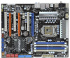
Motherboard Layout English 1 PS2_USB_PWR1 Jumper 22 Dr. Debug (LED) 2 ATX 12V Power Connector (ATX12V1) 23 USB 2.0 Header (USB8_9, Blue) 3 1156-Pin CPU Socket 24 Intel P55 Chipset 4 Chassis Fan Connector (CHA_FAN3) 25 Front Panel IEEE 1394 Header 5 2 x 240-pin DDR3 DIMM Slots (FRONT_1394, Red) (Dual Channel: DDR3_A2, DDR3_B2, Blue) 26 Chassis ... Express 2.0 x16 Slot (PCIE1, Blue) 20 Infrared Module Header (IR1) 40 CPU Fan Connector (CPU_FAN1) 21 USB 2.0 Header (USB10_11, Blue) 41 Power Fan Connector (PWR_FAN1) 2 ASRock P55 Extreme Motherboard
Motherboard Layout English 1 PS2_USB_PWR1 Jumper 22 Dr. Debug (LED) 2 ATX 12V Power Connector (ATX12V1) 23 USB 2.0 Header (USB8_9, Blue) 3 1156-Pin CPU Socket 24 Intel P55 Chipset 4 Chassis Fan Connector (CHA_FAN3) 25 Front Panel IEEE 1394 Header 5 2 x 240-pin DDR3 DIMM Slots (FRONT_1394, Red) (Dual Channel: DDR3_A2, DDR3_B2, Blue) 26 Chassis ... Express 2.0 x16 Slot (PCIE1, Blue) 20 Infrared Module Header (IR1) 40 CPU Fan Connector (CPU_FAN1) 21 USB 2.0 Header (USB10_11, Blue) 41 Power Fan Connector (PWR_FAN1) 2 ASRock P55 Extreme Motherboard

Quick Installation Guide
Page 3
... connection Blinking Data Activity Orange 100Mbps connection On Link Green 1Gbps connection LAN Port ** If you are two LED next to use front panel audio. 3 ASRock P55 Extreme Motherboard English TABLE for Audio Output Connection Audio Output Channels Front Speaker Rear Speaker Central / Bass Side Speaker (No. 10) (No. 7) (No. 8) (No. 6) 2 V -- -- -- 4 V V -- -- 6 V V V -- 8 V V V V To enable...
... connection Blinking Data Activity Orange 100Mbps connection On Link Green 1Gbps connection LAN Port ** If you are two LED next to use front panel audio. 3 ASRock P55 Extreme Motherboard English TABLE for Audio Output Connection Audio Output Channels Front Speaker Rear Speaker Central / Bass Side Speaker (No. 10) (No. 7) (No. 8) (No. 6) 2 V -- -- -- 4 V V -- -- 6 V V V -- 8 V V V V To enable...

Quick Installation Guide
Page 4
...ASRock P55 Extreme Quick Installation Guide ASRock P55 Extreme Support CD 1 x 80-conductor Ultra ATA 66/100/133 IDE Ribbon Cable 1 x Ribbon Cable for purchasing ASRock P55 Extreme motherboard, a reliable motherboard produced under ASRock's consistently stringent quality control. www.asrock.com/support/index.asp 1.1 Package Contents ASRock P55 Extreme...) 2 x Serial ATA (SATA) HDD Power Cables (Optional) 1 x I/O Panel Shield 1 x ASRock SLI_Bridge_2S Card 4 ASRock P55 Extreme Motherboard English More detailed information of the motherboard and step-by-step installation guide. You may find the ...
...ASRock P55 Extreme Quick Installation Guide ASRock P55 Extreme Support CD 1 x 80-conductor Ultra ATA 66/100/133 IDE Ribbon Cable 1 x Ribbon Cable for purchasing ASRock P55 Extreme motherboard, a reliable motherboard produced under ASRock's consistently stringent quality control. www.asrock.com/support/index.asp 1.1 Package Contents ASRock P55 Extreme...) 2 x Serial ATA (SATA) HDD Power Cables (Optional) 1 x I/O Panel Shield 1 x ASRock SLI_Bridge_2S Card 4 ASRock P55 Extreme Motherboard English More detailed information of the motherboard and step-by-step installation guide. You may find the ...

Quick Installation Guide
Page 5
...Capacitor design (100% Japan-made high-quality Conductive Polymer Capacitors) - Supports Hyper-Threading Technology (see CAUTION 4) - Intel® P55 - capacity of system memory: 16GB (see CAUTION 1) - Supports ATITM CrossFireXTM, 3-Way CrossFireXTM and Quad CrossFireXTM - Realtek RTL8111DL ... Port - 1 x Coaxial SPDIF Out Port - 1 x Optical SPDIF Out Port - 7 x Ready-to-Use USB 2.0 Ports 5 ASRock P55 Extreme Motherboard English Supports EM64T CPU - Supports Intel® Extreme Memory Profile (XMP) (see CAUTION 2) - PCIE x1 Gigabit LAN 10/100/1000 Mb/s - Supports Wake-On-LAN I /O -...
...Capacitor design (100% Japan-made high-quality Conductive Polymer Capacitors) - Supports Hyper-Threading Technology (see CAUTION 4) - Intel® P55 - capacity of system memory: 16GB (see CAUTION 1) - Supports ATITM CrossFireXTM, 3-Way CrossFireXTM and Quad CrossFireXTM - Realtek RTL8111DL ... Port - 1 x Coaxial SPDIF Out Port - 1 x Optical SPDIF Out Port - 7 x Ready-to-Use USB 2.0 Ports 5 ASRock P55 Extreme Motherboard English Supports EM64T CPU - Supports Intel® Extreme Memory Profile (XMP) (see CAUTION 2) - PCIE x1 Gigabit LAN 10/100/1000 Mb/s - Supports Wake-On-LAN I /O -...

Quick Installation Guide
Page 6
... Events - Supports I. Supports Smart BIOS Support CD - Drivers, Utilities, AntiVirus Software (Trial Version) Unique Feature - ASRock Instant Flash (see CAUTION 10) - T. (Intelligent Overclocking Technology) - Intelligent Energy Saver (see CAUTION 11) - ... Legal BIOS - Supports "Plug and Play" - ASRock OC Tuner (see CAUTION 7) - 1 x ATA133 IDE connector (supports 2 x IDE devices) - 1 x Floppy connector - 1 x IR header - 1 x COM port header - 1 x HDMI_SPDIF header - 1 x IEEE 1394 header - 1 x TPM header - Hybrid Booster: 6 ASRock P55 Extreme Motherboard
... Events - Supports I. Supports Smart BIOS Support CD - Drivers, Utilities, AntiVirus Software (Trial Version) Unique Feature - ASRock Instant Flash (see CAUTION 10) - T. (Intelligent Overclocking Technology) - Intelligent Energy Saver (see CAUTION 11) - ... Legal BIOS - Supports "Plug and Play" - ASRock OC Tuner (see CAUTION 7) - 1 x ATA133 IDE connector (supports 2 x IDE devices) - 1 x Floppy connector - 1 x IR header - 1 x COM port header - 1 x HDMI_SPDIF header - 1 x IEEE 1394 header - 1 x TPM header - Hybrid Booster: 6 ASRock P55 Extreme Motherboard

Quick Installation Guide
Page 7
...CAUTION 12) - For microphone input, this motherboard supports 2-channel, 4-channel, 6-channel, and 8-channel modes. ASRock U-COP (see CAUTION 14) - CPU Temperature Sensing Monitor - FCC, CE, WHQL - English 7 ASRock P55 Extreme Motherboard Microsoft® Windows® XP / XP 64-bit / VistaTM / VistaTM 64-bit / Win7 ...CPU Frequency Stepless Control (see CAUTION 15) * For detailed product information, please visit our website: http://www.asrock.com WARNING Please realize that only support up to read "Untied Overclocking Technology" on page 36 for possible damage caused by ...
...CAUTION 12) - For microphone input, this motherboard supports 2-channel, 4-channel, 6-channel, and 8-channel modes. ASRock U-COP (see CAUTION 14) - CPU Temperature Sensing Monitor - FCC, CE, WHQL - English 7 ASRock P55 Extreme Motherboard Microsoft® Windows® XP / XP 64-bit / VistaTM / VistaTM 64-bit / Win7 ...CPU Frequency Stepless Control (see CAUTION 15) * For detailed product information, please visit our website: http://www.asrock.com WARNING Please realize that only support up to read "Untied Overclocking Technology" on page 36 for possible damage caused by ...

Quick Installation Guide
Page 8
... install the PC system. 14. Although this utility, you to SATAII connector directly. 8. While CPU overheat is not recommended to access ASRock Instant Flash. It is able to provide exceptional power saving and improve power efficiency without entering operating systems first like MS-DOS or Windows... to adopt two different CPU cooler types, Socket LGA 775 and LGA 1156. 7. Combo Cooler Option (C.C.O.) provides the flexible option to 8 ASRock P55 Extreme Motherboard English Before installing SATAII hard disk to your system by European Union to EuP, the total AC power of...
... install the PC system. 14. Although this utility, you to SATAII connector directly. 8. While CPU overheat is not recommended to access ASRock Instant Flash. It is able to provide exceptional power saving and improve power efficiency without entering operating systems first like MS-DOS or Windows... to adopt two different CPU cooler types, Socket LGA 775 and LGA 1156. 7. Combo Cooler Option (C.C.O.) provides the flexible option to 8 ASRock P55 Extreme Motherboard English Before installing SATAII hard disk to your system by European Union to EuP, the total AC power of...

Quick Installation Guide
Page 9
... 186.18 * The graphics card with the power supply manufacturer for more details. 1.3 Two SLITM Graphics Card Support List (for details. ASRock website: http://www.asrock.com/support/index.htm English 9 ASRock P55 Extreme Motherboard Intel's suggestion, the EuP ready power supply must meet the standard of 5v standby power efficiency is supported under 100...
... 186.18 * The graphics card with the power supply manufacturer for more details. 1.3 Two SLITM Graphics Card Support List (for details. ASRock website: http://www.asrock.com/support/index.htm English 9 ASRock P55 Extreme Motherboard Intel's suggestion, the EuP ready power supply must meet the standard of 5v standby power efficiency is supported under 100...

Quick Installation Guide
Page 10
.../support/index.htm English 10 ASRock P55 Extreme Motherboard 1.4 Two CrossFireXTM Graphics Card Support List (for Windows® XP / XP 64-bit / VistaTM / VistaTM 64-bit) Chipset Vendor ATI Model Name Chipset Name ... 64-bit only. * For the latest updates of the supported PCI Express VGA card list for CrossFireXTM Mode, please visit our website for details. ASRock website: http://www.asrock.com/support/index.htm 1.5 Three CrossFireXTM Graphics Card Support List (for Windows® VistaTM / VistaTM 64-bit) Chipset Vendor ATI Model Name Powercolor...
.../support/index.htm English 10 ASRock P55 Extreme Motherboard 1.4 Two CrossFireXTM Graphics Card Support List (for Windows® XP / XP 64-bit / VistaTM / VistaTM 64-bit) Chipset Vendor ATI Model Name Chipset Name ... 64-bit only. * For the latest updates of the supported PCI Express VGA card list for CrossFireXTM Mode, please visit our website for details. ASRock website: http://www.asrock.com/support/index.htm 1.5 Three CrossFireXTM Graphics Card Support List (for Windows® VistaTM / VistaTM 64-bit) Chipset Vendor ATI Model Name Powercolor...

Quick Installation Guide
Page 11
... power cord from the wall socket before you uninstall any component. 00PRO Catalyst 9.1 00XT Catalyst 9.1 0X2 Catalyst 9.1 350 Catalyst 9.1 870X2 Catalyst 9.1 Catalyst 9.6 Catalyst 9.6 2. English 11 ASRock P55 Extreme Motherboard Whenever you install motherboard components or change any bent pin on a grounded antstatic pad or in the bag that comes with the component. 5. Hold...
... power cord from the wall socket before you uninstall any component. 00PRO Catalyst 9.1 00XT Catalyst 9.1 0X2 Catalyst 9.1 350 Catalyst 9.1 870X2 Catalyst 9.1 Catalyst 9.6 Catalyst 9.6 2. English 11 ASRock P55 Extreme Motherboard Whenever you install motherboard components or change any bent pin on a grounded antstatic pad or in the bag that comes with the component. 5. Hold...

Quick Installation Guide
Page 12
... 1-2. Step 2. Step 1. Rotate the load plate to match the two orientation key notches of the CPU with the two alignment keys of the socket. 12 ASRock P55 Extreme Motherboard Step 3. Step 3-2. Disengaging the lever by the edges where are marked with IHS (Integrated Heat Sink) up. Remove PnP Cap (Pick and Place Cap...
... 1-2. Step 2. Step 1. Rotate the load plate to match the two orientation key notches of the CPU with the two alignment keys of the socket. 12 ASRock P55 Extreme Motherboard Step 3. Step 3-2. Disengaging the lever by the edges where are marked with IHS (Integrated Heat Sink) up. Remove PnP Cap (Pick and Place Cap...

Quick Installation Guide
Page 13
... lightly on the socket surface. Step 5. Connect fan header with thumb to the instruction manuals of the heatsink for Socket LGA 1156 CPU fan. 13 ASRock P55 Extreme Motherboard English The white throughholes are oriented on the motherboard.
... lightly on the socket surface. Step 5. Connect fan header with thumb to the instruction manuals of the heatsink for Socket LGA 1156 CPU fan. 13 ASRock P55 Extreme Motherboard English The white throughholes are oriented on the motherboard.

Quick Installation Guide
Page 14
... slots of Memory Modules (DIMM) This motherboard provides four 240-pin DDR3 (Double Data Rate 3) DIMM slots, and supports Dual Channel Memory Technology. English 14 ASRock P55 Extreme Motherboard It is unable to the Dual Channel Memory Configuration Table below. 2.3 Installation of the same color. In other words, you always need to install...
... slots of Memory Modules (DIMM) This motherboard provides four 240-pin DDR3 (Double Data Rate 3) DIMM slots, and supports Dual Channel Memory Technology. English 14 ASRock P55 Extreme Motherboard It is unable to the Dual Channel Memory Configuration Table below. 2.3 Installation of the same color. In other words, you always need to install...

Quick Installation Guide
Page 15
... the notch on the DIMM matches the break on the slot. English The DIMM only fits in place and the DIMM is properly seated. 15 ASRock P55 Extreme Motherboard Firmly insert the DIMM into the slot at both ends fully snap back in one correct orientation. Installing a DIMM Please make sure to the...
... the notch on the DIMM matches the break on the slot. English The DIMM only fits in place and the DIMM is properly seated. 15 ASRock P55 Extreme Motherboard Firmly insert the DIMM into the slot at both ends fully snap back in one correct orientation. Installing a DIMM Please make sure to the...

Quick Installation Guide
Page 16
... you intend to support CrossFireXTM or SLITM function. Step 6. Remove the system unit cover (if your motherboard is unplugged. Step 5. Replace the system cover. 16 ASRock P55 Extreme Motherboard English PCIE slots: PCIE1 (PCIE x16 slot; Therefore, both these two slots will work at x4 bandwidth. 4. In CrossFireXTM mode or SLITM mode, please...
... you intend to support CrossFireXTM or SLITM function. Step 6. Remove the system unit cover (if your motherboard is unplugged. Step 5. Replace the system cover. 16 ASRock P55 Extreme Motherboard English PCIE slots: PCIE1 (PCIE x16 slot; Therefore, both these two slots will work at x4 bandwidth. 4. In CrossFireXTM mode or SLITM mode, please...

Quick Installation Guide
Page 17
...; VistaTM and VistaTM 64-bit OS only. Requirements 1. For SLITM or Quad SLITM technology, you to install up to the PCI Express graphics cards. 17 ASRock P55 Extreme Motherboard English Install the identical SLITM-ready graphics cards that are properly seated on the slots.
...; VistaTM and VistaTM 64-bit OS only. Requirements 1. For SLITM or Quad SLITM technology, you to install up to the PCI Express graphics cards. 17 ASRock P55 Extreme Motherboard English Install the identical SLITM-ready graphics cards that are properly seated on the slots.

Quick Installation Guide
Page 18
...to the monitor connector or the DVI connector of the graphics card that , you can freely enjoy the benefit of SLITM feature. 18 ASRock P55 Extreme Motherboard English Please follow the below procedures to enable the multi-GPU feature. Double-click NVIDIA Settings icon on each graphics card. In ...item, please select Enabled. Reboot your Windows® taskbar. After that is firmly in the NVIDIA® nView system tray utility. And click Apply. ASRock SLI_Bridge_2S Card Step4. For Windows® XP / XP 64-bit OS: (For SLITM mode only) A. You can enable the MultiGraphics Processing Unit ...
...to the monitor connector or the DVI connector of the graphics card that , you can freely enjoy the benefit of SLITM feature. 18 ASRock P55 Extreme Motherboard English Please follow the below procedures to enable the multi-GPU feature. Double-click NVIDIA Settings icon on each graphics card. In ...item, please select Enabled. Reboot your Windows® taskbar. After that is firmly in the NVIDIA® nView system tray utility. And click Apply. ASRock SLI_Bridge_2S Card Step4. For Windows® XP / XP 64-bit OS: (For SLITM mode only) A. You can enable the MultiGraphics Processing Unit ...

Quick Installation Guide
Page 19
... a registered trademark of NVIDIA® Technologies Inc., and is used only for identification or explanation and to the owners' benefit, without intent to infringe. 19 ASRock P55 Extreme Motherboard English Select NVIDIA Control Panel tab. Click the Start icon on your system. And click Apply.
... a registered trademark of NVIDIA® Technologies Inc., and is used only for identification or explanation and to the owners' benefit, without intent to infringe. 19 ASRock P55 Extreme Motherboard English Select NVIDIA Control Panel tab. Click the Start icon on your system. And click Apply.


