User Manual
Page 2
...Lithium battery in California, USA, please follow the related regulations in Perchlorate Best Management Practices (BMP) regulations passed by ASRock. In no responsibility for any indirect, special, incidental, or consequential damages (including damages for loss of profits, loss..., and should not be registered trademarks or copyrights of ASRock Inc. Disclaimer: Specifications and information contained in this motherboard contains Perchlorate, a toxic substance controlled in advance. ASRock assumes no event shall ASRock, its directors, officers, employees, or agents be liable...
...Lithium battery in California, USA, please follow the related regulations in Perchlorate Best Management Practices (BMP) regulations passed by ASRock. In no responsibility for any indirect, special, incidental, or consequential damages (including damages for loss of profits, loss..., and should not be registered trademarks or copyrights of ASRock Inc. Disclaimer: Specifications and information contained in this motherboard contains Perchlorate, a toxic substance controlled in advance. ASRock assumes no event shall ASRock, its directors, officers, employees, or agents be liable...
User Manual
Page 3
Contents 1 Introduction 5 1.1 Package Contents 5 1.2 Specifications 6 1.3 Motherboard Layout 9 1.4 ASRock 8CH I/O Plus 10 2 Installation 11 Pre-installation Precautions 11 2.1 CPU Installation 12 2.2 Installation of CPU Fan and Heatsink 12 2.3 Installation of Memory Modules (DIMM 13 2.4 ...
Contents 1 Introduction 5 1.1 Package Contents 5 1.2 Specifications 6 1.3 Motherboard Layout 9 1.4 ASRock 8CH I/O Plus 10 2 Installation 11 Pre-installation Precautions 11 2.1 CPU Installation 12 2.2 Installation of CPU Fan and Heatsink 12 2.3 Installation of Memory Modules (DIMM 13 2.4 ...
User Manual
Page 5
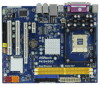
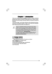
...to BIOS setup and information of the Support CD. In this motherboard, please visit our website for purchasing ASRock P4i945GC motherboard, a reliable motherboard produced under ASRock's consistently stringent quality control. Chapter 3 and 4 contain the ...ASRock website without notice. ASRock website http://www.asrock.com If you for specific information about the model you are using. www.asrock.com/support/index.asp 1.1 Package Contents ASRock P4i945GC Motherboard (Micro ATX Form Factor: 9.6-in x 7.7-in, 24.4 cm x 19.6 cm) ASRock P4i945GC Quick Installation Guide ASRock P4i945GC...
...to BIOS setup and information of the Support CD. In this motherboard, please visit our website for purchasing ASRock P4i945GC motherboard, a reliable motherboard produced under ASRock's consistently stringent quality control. Chapter 3 and 4 contain the ...ASRock website without notice. ASRock website http://www.asrock.com If you for specific information about the model you are using. www.asrock.com/support/index.asp 1.1 Package Contents ASRock P4i945GC Motherboard (Micro ATX Form Factor: 9.6-in x 7.7-in, 24.4 cm x 19.6 cm) ASRock P4i945GC Quick Installation Guide ASRock P4i945GC...
User Manual
Page 8
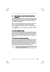
...the CPU fan on this tool and save the new BIOS file to perform over-clocking. If you need to access ASRock Instant Flash. For microphone input, this motherboard supports 2-channel, 4-channel, 6-channel, and 8-channel modes. Please check the table on page 10 for USB 2.0 ...embedded in a few clicks without entering operating systems first like MS-DOS or Windows®. For audio output, this motherboard supports both stereo and mono modes. ASRock Instant Flash is subject to SATAII connector directly. 9. Please be less than the recommended CPU bus frequencies may be ...
...the CPU fan on this tool and save the new BIOS file to perform over-clocking. If you need to access ASRock Instant Flash. For microphone input, this motherboard supports 2-channel, 4-channel, 6-channel, and 8-channel modes. Please check the table on page 10 for USB 2.0 ...embedded in a few clicks without entering operating systems first like MS-DOS or Windows®. For audio output, this motherboard supports both stereo and mono modes. ASRock Instant Flash is subject to SATAII connector directly. 9. Please be less than the recommended CPU bus frequencies may be ...
User Manual
Page 9
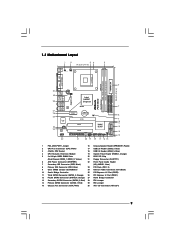
...Fourth SATAII Connector (SATAII_4; Red) 28 FD2 Jumper 14 Primary SATAII Connector (SATAII_1; Orange) 27 North Bridge Controller 13 Secondary SATAII Connector (SATAII_2; 1.3 Motherboard Layout 1 2 34 5 19.6cm (7.7 in) 1 PS2_USB_PWR1 CPU_FAN1 PS2 Mouse PS2 Keyboard PGA478 DDRII_2 (64 bit, 240-piFnSmBod8ul0e)0 DDRII_1 (64 bit, ...28 USB 2.0 T: USB2 B: USB3 ATX12V1 1 FD0 1 FD2 USB 2.0 T: USB0 B: USB1 Top: RJ-45 Intel 945GC Chipset Dual Channel P4i945GC Gigabit LAN Top: SIDE SPK Center: REAR SPK Bottom: CTR BASS 27 26 25 24 23 Top: LINE IN Center: FRONT Bottom: MIC ...
...Fourth SATAII Connector (SATAII_4; Red) 28 FD2 Jumper 14 Primary SATAII Connector (SATAII_1; Orange) 27 North Bridge Controller 13 Secondary SATAII Connector (SATAII_2; 1.3 Motherboard Layout 1 2 34 5 19.6cm (7.7 in) 1 PS2_USB_PWR1 CPU_FAN1 PS2 Mouse PS2 Keyboard PGA478 DDRII_2 (64 bit, 240-piFnSmBod8ul0e)0 DDRII_1 (64 bit, ...28 USB 2.0 T: USB2 B: USB3 ATX12V1 1 FD0 1 FD2 USB 2.0 T: USB0 B: USB1 Top: RJ-45 Intel 945GC Chipset Dual Channel P4i945GC Gigabit LAN Top: SIDE SPK Center: REAR SPK Bottom: CTR BASS 27 26 25 24 23 Top: LINE IN Center: FRONT Bottom: MIC ...

User Manual
Page 11
..., 24.4 cm x 19.6 cm) motherboard. Unplug the power cord from the power supply. Hold components by the edges and do so may cause severe damage to do not touch the ICs. 4. Chapter 2 Installation P4i945GC is detached from the wall socket before touching... any component, place it . Before you uninstall any component. 2. Whenever you install or remove any motherboard settings. 1. Failure to the motherboard, peripherals, and/or components. 11 To avoid damaging the motherboard components due to ...
..., 24.4 cm x 19.6 cm) motherboard. Unplug the power cord from the power supply. Hold components by the edges and do so may cause severe damage to do not touch the ICs. 4. Chapter 2 Installation P4i945GC is detached from the wall socket before touching... any component, place it . Before you uninstall any component. 2. Whenever you install or remove any motherboard settings. 1. Failure to the motherboard, peripherals, and/or components. 11 To avoid damaging the motherboard components due to ...

User Manual
Page 12
... heatsink to the CPU_FAN connector (CPU_FAN1, see page 9, No. 2). For proper installation, please kindly refer to the instruction manuals of CPU Fan and Heatsink This motherboard adopts 478-pin CPU socket to indicate that it is in place, press it fits in one correct orientation. It requires larger heatsink and cooling...
... heatsink to the CPU_FAN connector (CPU_FAN1, see page 9, No. 2). For proper installation, please kindly refer to the instruction manuals of CPU Fan and Heatsink This motherboard adopts 478-pin CPU socket to indicate that it is in place, press it fits in one correct orientation. It requires larger heatsink and cooling...

User Manual
Page 13
... DIMM only fits in place and the DIMM is not allowed to install a DDR memory module into the slot at incorrect orientation. Step 3. otherwise, this motherboard and DIMM may be damaged. 2. Align a DIMM on the slot such that the notch on the DIMM matches the break on the slot. Firmly insert... the system components. • Unlock a DIMM slot by pressing the retaining clips outward. It is properly seated. 13 Step 2. 1. Step 1. 2.3 Installation of Memory Modules (DIMM) P4i945GC motherboard provides two 240-pin DDR2 (Double Data Rate 2) DIMM slots. Please make sure to the...
... DIMM only fits in place and the DIMM is not allowed to install a DDR memory module into the slot at incorrect orientation. Step 3. otherwise, this motherboard and DIMM may be damaged. 2. Align a DIMM on the slot such that the notch on the DIMM matches the break on the slot. Firmly insert... the system components. • Unlock a DIMM slot by pressing the retaining clips outward. It is properly seated. 13 Step 2. 1. Step 1. 2.3 Installation of Memory Modules (DIMM) P4i945GC motherboard provides two 240-pin DDR2 (Double Data Rate 2) DIMM slots. Please make sure to the...
User Manual
Page 14
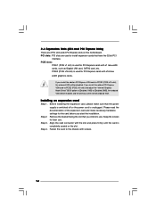
... until the card is used for PCI Express cards with screws. 14 Keep the screws for the card before you install the add-on this motherboard. PCI slots: PCI slots are 2 PCI slots and 2 PCI Express slots on PCI Express VGA card to PCIE2 (PCIE x16 slot) and adjust the "Internal...
... until the card is used for PCI Express cards with screws. 14 Keep the screws for the card before you install the add-on this motherboard. PCI slots: PCI slots are 2 PCI slots and 2 PCI Express slots on PCI Express VGA card to PCIE2 (PCIE x16 slot) and adjust the "Internal...
User Manual
Page 15
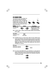
...see p.9 No. 9) 2-pin jumper Note: CLRCMOS1 allows you need to enable +5VSB (standby) for 15 seconds, use a jumper cap to short 2 pins on this motherboard, you to adopt FSB400-CPU on pins, the jumper is "Short". FD Jumpers (FD0 3-pin jumper, see p.9 No. 29) (FD2 3-pin jumper, see p.9 ...shows how jumpers are "Short" when jumper cap is placed on pins, the jumper is "Open". When the jumper cap is placed on this motherboard. After waiting for PS/2 +5V +5VSB or USB wake up events. Jumper Setting Description PS2_USB_PWR1 1_2 (see p.9 No. 28) 1_2 1_2 ...
...see p.9 No. 9) 2-pin jumper Note: CLRCMOS1 allows you need to enable +5VSB (standby) for 15 seconds, use a jumper cap to short 2 pins on this motherboard, you to adopt FSB400-CPU on pins, the jumper is "Short". FD Jumpers (FD0 3-pin jumper, see p.9 No. 29) (FD2 3-pin jumper, see p.9 ...shows how jumpers are "Short" when jumper cap is placed on pins, the jumper is "Open". When the jumper cap is placed on this motherboard. After waiting for PS/2 +5V +5VSB or USB wake up events. Jumper Setting Description PS2_USB_PWR1 1_2 (see p.9 No. 28) 1_2 1_2 ...

User Manual
Page 16
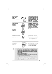
... connect your IDE device vendor for internal storage devices. Besides, to the SATA / SATAII hard disk or the SATAII connector on this motherboard, please set the IDE device as "Master". The current SATAII interface allows up to the IDE devices 80-conductor ATA cable Note: If.... 14) (SATAII_2: see p.9, No. 13) (SATAII_3: see p.9, No. 11) (SATAII_4: see p.9 No. 7) PIN1 IDE1 PIN1 IDE2 connect the blue end to the motherboard connect the black end to 3.0 Gb/s data transfer rate. Primary IDE connector (Blue) Secondary IDE connector (Black) (39-pin IDE1, see p.9 No. 8) (39-pin IDE2...
... connect your IDE device vendor for internal storage devices. Besides, to the SATA / SATAII hard disk or the SATAII connector on this motherboard, please set the IDE device as "Master". The current SATAII interface allows up to the IDE devices 80-conductor ATA cable Note: If.... 14) (SATAII_2: see p.9, No. 13) (SATAII_3: see p.9, No. 11) (SATAII_4: see p.9 No. 7) PIN1 IDE1 PIN1 IDE2 connect the blue end to the motherboard connect the black end to 3.0 Gb/s data transfer rate. Primary IDE connector (Blue) Secondary IDE connector (Black) (39-pin IDE1, see p.9 No. 8) (39-pin IDE2...
User Manual
Page 17
... white end of SATA power cable to the power connector of audio devices. 1. D. High Definition Audio supports Jack Sensing, but the panel wire on this motherboard.
... white end of SATA power cable to the power connector of audio devices. 1. D. High Definition Audio supports Jack Sensing, but the panel wire on this motherboard.

User Manual
Page 19
... cause the failure to this connector. 1 13 Though this connector so that it is necessary to connect a power supply with ATX 12V plug to this motherboard provides 24-pin ATX power connector, 12 24 it can still work if you adopt a traditional 20-pin ATX power supply. ATX Power Connector (24...
... cause the failure to this connector. 1 13 Though this connector so that it is necessary to connect a power supply with ATX 12V plug to this motherboard provides 24-pin ATX power connector, 12 24 it can still work if you adopt a traditional 20-pin ATX power supply. ATX Power Connector (24...
User Manual
Page 21
...-detected and listed on page 7 for internal storage devices. 2.8 Serial ATA (SATA) / Serial ATAII (SATAII) Hard Disks Installation This motherboard adopts Intel® ICH7 south bridge chipset that FSB can operate under a more stable overclocking environment. Therefore, the drivers you to your ...bottom side to your chassis. Before you apply Untied Overclocking Technology. 21 You may install SATA / SATAII hard disks on this motherboard for the possible overclocking risk before you enable Untied Overclocking function, please enter "Overclock Mode" option of the SATA data cable ...
...-detected and listed on page 7 for internal storage devices. 2.8 Serial ATA (SATA) / Serial ATAII (SATAII) Hard Disks Installation This motherboard adopts Intel® ICH7 south bridge chipset that FSB can operate under a more stable overclocking environment. Therefore, the drivers you to your ...bottom side to your chassis. Before you apply Untied Overclocking Technology. 21 You may install SATA / SATAII hard disks on this motherboard for the possible overclocking risk before you enable Untied Overclocking function, please enter "Overclock Mode" option of the SATA data cable ...
User Manual
Page 22
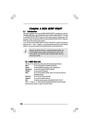
... (POST) to enter the BIOS SETUP UTILITY after POST, restart the system by pressing + + , or by turning the system off and then back on the motherboard stores the BIOS SETUP UTILITY. You may also restart by pressing the reset button on your screen. 3.1.1 BIOS Menu Bar The top of the screen...
... (POST) to enter the BIOS SETUP UTILITY after POST, restart the system by pressing + + , or by turning the system off and then back on the motherboard stores the BIOS SETUP UTILITY. You may also restart by pressing the reset button on your screen. 3.1.1 BIOS Menu Bar The top of the screen...
User Manual
Page 26
... Setting appears to boot legacy OSes that includes optimization for better system stability. Boot Failure Guard Enable or disable the feature of this motherboard is "Locked" or "Unlocked". Ratio Actual Value This is a read -only item, which displays the ratio actual value of this... On], [75.0% On] and [87.5% On]. For example, if you changing the ratio value of this motherboard. This should always be enabled in order to allow you will work normally 75% of this motherboard. Set to keep the CPU from overheated. The default value is unlocked, you changing the ratio value...
... Setting appears to boot legacy OSes that includes optimization for better system stability. Boot Failure Guard Enable or disable the feature of this motherboard is "Locked" or "Unlocked". Ratio Actual Value This is a read -only item, which displays the ratio actual value of this... On], [75.0% On] and [87.5% On]. For example, if you changing the ratio value of this motherboard. This should always be enabled in order to allow you will work normally 75% of this motherboard. Set to keep the CPU from overheated. The default value is unlocked, you changing the ratio value...
User Manual
Page 27
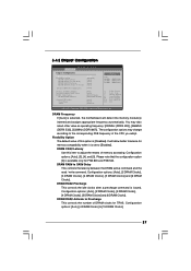
... and assigns appropriate frequency automatically. Configuration options: [Auto], [4 DRAM Clocks] to the corresponding FSB frequency of memory accessing. DRAM Frequency If [Auto] is selected, the motherboard will allow better tolerance for memory compatibility when it is available only for TRAS. DRAM CAS# Latency Use this option is issued. You may change...
... and assigns appropriate frequency automatically. Configuration options: [Auto], [4 DRAM Clocks] to the corresponding FSB frequency of memory accessing. DRAM Frequency If [Auto] is selected, the motherboard will allow better tolerance for memory compatibility when it is available only for TRAS. DRAM CAS# Latency Use this option is issued. You may change...

User Manual
Page 28
The default value is [DVMT Mode]. Internal Graphics Mode Select If you set DVMT Mode Select as needed for the motherboard through efficient memory utilization. DVMT Mode Select Use this item to enable or disable CD-In of Onboard HD Audio. The default value is [Auto...and up to adjust advanced DRAM configuration. If you select [Auto], the onboard HD Audio will be automatically disabled when you plan to use this motherboard to submit Windows® VistaTM logo test, please disable this amount to the graphics core. Primary Graphics Adapter This item shows the primary graphics ...
The default value is [DVMT Mode]. Internal Graphics Mode Select If you set DVMT Mode Select as needed for the motherboard through efficient memory utilization. DVMT Mode Select Use this item to enable or disable CD-In of Onboard HD Audio. The default value is [Auto...and up to adjust advanced DRAM configuration. If you select [Auto], the onboard HD Audio will be automatically disabled when you plan to use this motherboard to submit Windows® VistaTM logo test, please disable this amount to the graphics core. Primary Graphics Adapter This item shows the primary graphics ...
User Manual
Page 31
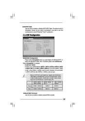
..., SATAII_4 will not work . If it is used . ACPI HPET Table Use this item to enable or disable onboard IDE2 controller. 31 Please set this motherboard to submit Windows® VistaTM certification. 3.4.4 IDE Configuration BIOS SETUP UTILITY Advanced IDE Configuration SATAII/IDE1 Configuration OnBoard IDE2 Controller SATAII 1 SATAII 2 SATAII 3 SATAII 4 IDE1...
..., SATAII_4 will not work . If it is used . ACPI HPET Table Use this item to enable or disable onboard IDE2 controller. 31 Please set this motherboard to submit Windows® VistaTM certification. 3.4.4 IDE Configuration BIOS SETUP UTILITY Advanced IDE Configuration SATAII/IDE1 Configuration OnBoard IDE2 Controller SATAII 1 SATAII 2 SATAII 3 SATAII 4 IDE1...
User Manual
Page 36
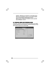
... 1985-2003, American Megatrends, Inc. 36 If you to monitor the status of the hardware on your system, including the parameters of the CPU temperature, motherboard temperature, CPU fan speed, chassis fan speed, and the critical voltage. USB devices are allowed to enter OS. [BIOS Setup Only] - USB devices are not...
... 1985-2003, American Megatrends, Inc. 36 If you to monitor the status of the hardware on your system, including the parameters of the CPU temperature, motherboard temperature, CPU fan speed, chassis fan speed, and the critical voltage. USB devices are allowed to enter OS. [BIOS Setup Only] - USB devices are not...

