
User Manual
Page 3
Contents 1 Introduction 5 1.1 Package Contents 5 1.2 Specifications 6 1.3 Motherboard Layout 8 1.4 ASRock 8CH I/O 9 2 Installation 10 Pre-installation Precautions 10 2.1 CPU Installation 11 2.2 Installation of CPU Fan and Heatsink 11 2.3 Installation of Memory Modules (DIMM 12 2.4 Expansion Slots (...
Contents 1 Introduction 5 1.1 Package Contents 5 1.2 Specifications 6 1.3 Motherboard Layout 8 1.4 ASRock 8CH I/O 9 2 Installation 10 Pre-installation Precautions 10 2.1 CPU Installation 11 2.2 Installation of CPU Fan and Heatsink 11 2.3 Installation of Memory Modules (DIMM 12 2.4 Expansion Slots (...
User Manual
Page 5
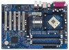
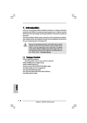
... on our website as well. website without notice. You may find the latest memory and CPU support lists on ASRock. Because the motherboard specifications and the BIOS software might be updated, the content of this manual, chapter 1 and 2 contain introduction of... One Serial ATA (SATA) HDD Power Cable (Optional) One ASRock 8CH I/O 5 ASRock website http://www.asrock.com 1.1 Package Contents ASRock P4i65PE Motherboard (ATX Form Factor: 12.0-in x 8.2-in, 30.5 cm x 20.8 cm) ASRock P4i65PE Quick Installation Guide ASRock P4i65PE Support CD One 80-conductor Ultra ATA 66/100 IDE Ribbon...
... on our website as well. website without notice. You may find the latest memory and CPU support lists on ASRock. Because the motherboard specifications and the BIOS software might be updated, the content of this manual, chapter 1 and 2 contain introduction of... One Serial ATA (SATA) HDD Power Cable (Optional) One ASRock 8CH I/O 5 ASRock website http://www.asrock.com 1.1 Package Contents ASRock P4i65PE Motherboard (ATX Form Factor: 12.0-in x 8.2-in, 30.5 cm x 20.8 cm) ASRock P4i65PE Quick Installation Guide ASRock P4i65PE Support CD One 80-conductor Ultra ATA 66/100 IDE Ribbon...

User Manual
Page 7
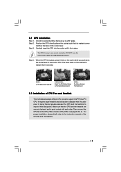
... or damage the CPU. 7 Please check the table below for proper connection. 8. It may cause permanent damage! 6. Although this motherboard offers stepless control, it will automatically shutdown. CPU FSB Frequency Memory Support Frequency 800 DDR266, DDR320*, DDR400 533 DDR266, DDR333 400 ...DDR266 * When you resume the system, please check if the CPU fan on this motherboard supports 2-channel, 4-channel, 6-channel, and 8-channel modes. It may not work properly under Microsoft® Windows® XP SP1 ...
... or damage the CPU. 7 Please check the table below for proper connection. 8. It may cause permanent damage! 6. Although this motherboard offers stepless control, it will automatically shutdown. CPU FSB Frequency Memory Support Frequency 800 DDR266, DDR320*, DDR400 533 DDR266, DDR333 400 ...DDR266 * When you resume the system, please check if the CPU fan on this motherboard supports 2-channel, 4-channel, 6-channel, and 8-channel modes. It may not work properly under Microsoft® Windows® XP SP1 ...

User Manual
Page 10
...following precautions before you handle components. 3. To avoid damaging the motherboard components due to static electricity, NEVER place your chassis to the motherboard, peripherals, and/or components. 10 Before you uninstall any motherboard settings. 1. Pre-installation Precautions Take note of your motherboard directly on a grounded antistatic pad or in , 30.5 cm ...or the power cord is an ATX form factor (12.0-in x 8.2-in the bag that comes with the component. Chapter 2 Installation P4i65PE is detached from the power supply. Before you install or remove any component. 2.
...following precautions before you handle components. 3. To avoid damaging the motherboard components due to static electricity, NEVER place your chassis to the motherboard, peripherals, and/or components. 10 Before you uninstall any motherboard settings. 1. Pre-installation Precautions Take note of your motherboard directly on a grounded antistatic pad or in , 30.5 cm ...or the power cord is an ATX form factor (12.0-in x 8.2-in the bag that comes with the component. Chapter 2 Installation P4i65PE is detached from the power supply. Before you install or remove any component. 2.
User Manual
Page 11
... that it is in place, press it fits in place. Make sure that its marked corner matches the base of CPU Fan and Heatsink This motherboard adopts 478-pin CPU socket to a 90° angle. Unlock the socket by lifting the lever up to support Intel® Pentium®4 CPU. Step...
... that it is in place, press it fits in place. Make sure that its marked corner matches the base of CPU Fan and Heatsink This motherboard adopts 478-pin CPU socket to a 90° angle. Unlock the socket by lifting the lever up to support Intel® Pentium®4 CPU. Step...

User Manual
Page 12
... them in the slots of the same color. You may refer to install identical DDR DIMM pair in the slots of Memory Modules (DIMM) P4i65PE motherboard provides four 184-pin DDR (Double Data Rate) DIMM slots, and supports Dual Channel Memory Technology. see p.8 No. 6), so that Dual ... install identical DDR DIMMs in Dual Channel B (DDR2 and DDR4; see p.8 No. 5) or identical DDR DIMM pair in all four slots. This motherboard also allows you have to the Dual Channel Memory Configuration Table below. Populated - In other words, you to activate the Dual Channel Memory Technology. ...
... them in the slots of the same color. You may refer to install identical DDR DIMM pair in the slots of Memory Modules (DIMM) P4i65PE motherboard provides four 184-pin DDR (Double Data Rate) DIMM slots, and supports Dual Channel Memory Technology. see p.8 No. 6), so that Dual ... install identical DDR DIMMs in Dual Channel B (DDR2 and DDR4; see p.8 No. 5) or identical DDR DIMM pair in all four slots. This motherboard also allows you have to the Dual Channel Memory Configuration Table below. Populated - In other words, you to activate the Dual Channel Memory Technology. ...

User Manual
Page 13
... 2. Step 1. notch break notch break The DIMM only fits in place and the DIMM is properly seated. 13 Installing a DIMM Please make sure to the motherboard and the DIMM if you force the DIMM into the slot until the retaining clips at incorrect orientation.
... 2. Step 1. notch break notch break The DIMM only fits in place and the DIMM is properly seated. 13 Installing a DIMM Please make sure to the motherboard and the DIMM if you force the DIMM into the slot until the retaining clips at incorrect orientation.

User Manual
Page 14
...cord is completely seated on the slot. AGP slot: The AGP slot is already installed in a chassis). Remove the system unit cover (if your motherboard is used to install a graphics card. Step 2. Fasten the card to use. Step 6. 2.4 Expansion Slots (PCI and AGP Slots) There ...card Step 1. Step 4. Step 5. Before installing the expansion card, please make necessary hardware settings for later use a 3.3V AGP card on P4i65PE motherboard. Step 3. Align the card connector with screws. Remove the bracket facing the slot that you start the installation. Keep the screws for the card...
...cord is completely seated on the slot. AGP slot: The AGP slot is already installed in a chassis). Remove the system unit cover (if your motherboard is used to install a graphics card. Step 2. Fasten the card to use. Step 6. 2.4 Expansion Slots (PCI and AGP Slots) There ...card Step 1. Step 4. Step 5. Before installing the expansion card, please make necessary hardware settings for later use a 3.3V AGP card on P4i65PE motherboard. Step 3. Align the card connector with screws. Remove the bracket facing the slot that you start the installation. Keep the screws for the card...

User Manual
Page 16
... current SATA interface allows up to the IDE devices 80-conductor ATA 66/100 cable Note: If you use only one IDE device on the motherboard. 16 FDD connector (33-pin FLOPPY1) (see p.8 No. 21) Pin1 FLOPPY1 the red-striped side to Pin1 Note: Make sure the red-striped side of... the cable is plugged into Pin1 side of the SATA data cable can be connected to the instruction of the motherboard! Do NOT place jumper caps over the headers and connectors will cause permanent damage of your hard disk drive to the primary IDE connector (IDE1...
... current SATA interface allows up to the IDE devices 80-conductor ATA 66/100 cable Note: If you use only one IDE device on the motherboard. 16 FDD connector (33-pin FLOPPY1) (see p.8 No. 21) Pin1 FLOPPY1 the red-striped side to Pin1 Note: Make sure the red-striped side of... the cable is plugged into Pin1 side of the SATA data cable can be connected to the instruction of the motherboard! Do NOT place jumper caps over the headers and connectors will cause permanent damage of your hard disk drive to the primary IDE connector (IDE1...
User Manual
Page 19
...3: Connect one end of the OnBoard IDE Operate Mode option in BIOS setup is complete at this motherboard for internal storage devices. For the configuration details, please refer to the motherboard's secondary SATA connector (SATA2). You may install SATA hard disks on page 26. 19 If you... and ensure the configuration of the SATA data cable to install the SATA hard disks. Before you to the motherboard's primary SATA connector (SATA1). 2.7 Serial ATA (SATA) Hard Disks Installation This motherboard adopts Intel ICH5 south bridge chipset that supports Serial ATA (SATA) hard disks.
...3: Connect one end of the OnBoard IDE Operate Mode option in BIOS setup is complete at this motherboard for internal storage devices. For the configuration details, please refer to the motherboard's secondary SATA connector (SATA2). You may install SATA hard disks on page 26. 19 If you... and ensure the configuration of the SATA data cable to install the SATA hard disks. Before you to the motherboard's primary SATA connector (SATA1). 2.7 Serial ATA (SATA) Hard Disks Installation This motherboard adopts Intel ICH5 south bridge chipset that supports Serial ATA (SATA) hard disks.
User Manual
Page 20
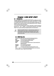
... press to enter the BIOS SETUP UTILITY after POST, restart the system by pressing + + , or by turning the system off and then back on the motherboard stores the BIOS SETUP UTILITY. You may not exactly match what you see on the system chassis. Because the BIOS software is constantly being updated...
... press to enter the BIOS SETUP UTILITY after POST, restart the system by pressing + + , or by turning the system off and then back on the motherboard stores the BIOS SETUP UTILITY. You may not exactly match what you see on the system chassis. Because the BIOS software is constantly being updated...
User Manual
Page 22
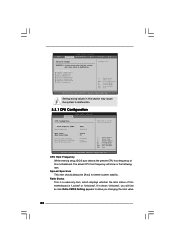
CPU Host Frequency While entering setup, BIOS auto detects the present CPU host frequency of this motherboard. If it shows "Unlocked", you will show in the following item. Main BIOS SETUP UTILITY Advanced H/W Monitor Boot Security Exit Advanced Settings WARNING : ...Exit v02.54 (C) Copyright 1985-2003, American Megatrends, Inc. Ratio Status This is a read-only item, which displays whether the ratio status of this motherboard is "Locked" or "Unlocked". Spread Spectrum This item should always be [Auto] for better system stability. The actual CPU host frequency will find an ...
CPU Host Frequency While entering setup, BIOS auto detects the present CPU host frequency of this motherboard. If it shows "Unlocked", you will show in the following item. Main BIOS SETUP UTILITY Advanced H/W Monitor Boot Security Exit Advanced Settings WARNING : ...Exit v02.54 (C) Copyright 1985-2003, American Megatrends, Inc. Ratio Status This is a read-only item, which displays whether the ratio status of this motherboard is "Locked" or "Unlocked". Spread Spectrum This item should always be [Auto] for better system stability. The actual CPU host frequency will find an ...

User Manual
Page 23
... should be hidden. 23 It will be hidden. Max CPUID Value Limit For Prescott CPU only, some OSes (ex. otherwise, this motherboard. If you use the ratio value to CAS# Delay [4 Clocks] DRAM Precharge Delay [8 Clocks] DRAM Burst Length [4] Memory Hole Init. This option will only work ...
... should be hidden. 23 It will be hidden. Max CPUID Value Limit For Prescott CPU only, some OSes (ex. otherwise, this motherboard. If you use the ratio value to CAS# Delay [4 Clocks] DRAM Precharge Delay [8 Clocks] DRAM Burst Length [4] Memory Hole Init. This option will only work ...
User Manual
Page 24
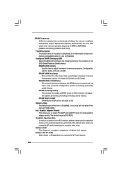
... minimum. Configuration options: [8 Clocks], [7 Clocks], [6 Clocks], and [5 Clocks]. Memory Hole The default value of this option is [Disabled]. DRAM Frequency If [Auto] is selected, the motherboard will configure the following items by SPD Select [Enabled] will detect the memory module(s) inserted and assigns appropriate frequency automatically. Configuration options: [4 Clocks], [3 Clocks], and...
... minimum. Configuration options: [8 Clocks], [7 Clocks], [6 Clocks], and [5 Clocks]. Memory Hole The default value of this option is [Disabled]. DRAM Frequency If [Auto] is selected, the motherboard will configure the following items by SPD Select [Enabled] will detect the memory module(s) inserted and assigns appropriate frequency automatically. Configuration options: [4 Clocks], [3 Clocks], and...

User Manual
Page 31
... support. 3.4 Hardware Health Event Monitoring Screen In this item to enable or disable the support to enable or disable the use of the CPU temperature, motherboard temperature, CPU fan speed, chassis fan speed, and the critical voltage. if there is no USB device connected, "Auto" option will start to enable or...
... support. 3.4 Hardware Health Event Monitoring Screen In this item to enable or disable the support to enable or disable the use of the CPU temperature, motherboard temperature, CPU fan speed, chassis fan speed, and the critical voltage. if there is no USB device connected, "Auto" option will start to enable or...
User Manual
Page 35
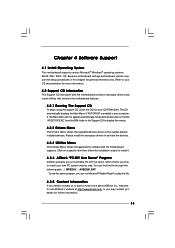
... own PC system step by step. or you how to your OS documentation for more about ASRock Inc., welcome to activate the devices. 4.2.3 Utilities Menu The Utilities Menu shows the applications software that enhance the motherboard features. 4.2.1 Running The Support CD To begin using the support CD, insert the CD into your...
... own PC system step by step. or you how to your OS documentation for more about ASRock Inc., welcome to activate the devices. 4.2.3 Utilities Menu The Utilities Menu shows the applications software that enhance the motherboard features. 4.2.1 Running The Support CD To begin using the support CD, insert the CD into your...
Quick Installation Guide
Page 1
... damages (including damages for loss of profits, loss of business, loss of data, interruption of business and the like), even if ASRock has been advised of the possibility of such damages arising from any defect or error in the guide or product. Disclaimer: Specifications and... names appearing in any form or by any interference received, including interference that may cause undesired operation. All rights reserved. 1 ASRock P4i65PE Motherboard English With respect to the contents of this guide may or may not be registered trademarks or copyrights of their respective companies, and...
... damages (including damages for loss of profits, loss of business, loss of data, interruption of business and the like), even if ASRock has been advised of the possibility of such damages arising from any defect or error in the guide or product. Disclaimer: Specifications and... names appearing in any form or by any interference received, including interference that may cause undesired operation. All rights reserved. 1 ASRock P4i65PE Motherboard English With respect to the contents of this guide may or may not be registered trademarks or copyrights of their respective companies, and...
Quick Installation Guide
Page 2
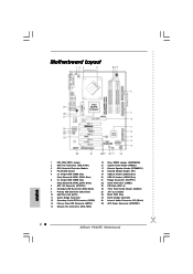
... Jumpers 26 BIOS FWH Chip 27 North Bridge Controller 28 Internal Audio Connector: CD1 (Black) 29 ATX Power Connector (ATXPWR1) 2 ASRock P4i65PE Motherboard Blue) 6 2 x 184-pin DDR DIMM Slots (Dual Channel B: DDR2, DDR4; Motherboard Layout English 1 PS2_USB_PWR1 Jumper 2 CPU Fan Connector (CPU_FAN1) 3 CPU Heatsink Retention Module 4 P4-478 CPU Socket 5 2 x 184-pin DDR DIMM...
... Jumpers 26 BIOS FWH Chip 27 North Bridge Controller 28 Internal Audio Connector: CD1 (Black) 29 ATX Power Connector (ATXPWR1) 2 ASRock P4i65PE Motherboard Blue) 6 2 x 184-pin DDR DIMM Slots (Dual Channel B: DDR2, DDR4; Motherboard Layout English 1 PS2_USB_PWR1 Jumper 2 CPU Fan Connector (CPU_FAN1) 3 CPU Heatsink Retention Module 4 P4-478 CPU Socket 5 2 x 184-pin DDR DIMM...
Quick Installation Guide
Page 3
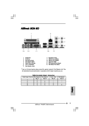
TABLE for connection details in accordance with the type of speaker you use . ASRock 8CH I/O 1 Parallel Port 2 RJ-45 Port 3 Side Speaker (Gray) 4 Rear Speaker (Black) 5 Central / Bass (Orange) 6 Line In (Light Blue) *7 Front Speaker (Lime) 8 Microphone (Pink) 9 USB 2.0 ... Speaker Jack". See the table below for Audio Output Connection Audio Output Channels Front Speaker Rear Speaker Central / Bass (No. 7) (No. 4) (No. 5) 2 V -- -- 4 V V -- 6 V V V 8 V V V Side Speaker (No. 3) ---V 3 ASRock P4i65PE Motherboard English
TABLE for connection details in accordance with the type of speaker you use . ASRock 8CH I/O 1 Parallel Port 2 RJ-45 Port 3 Side Speaker (Gray) 4 Rear Speaker (Black) 5 Central / Bass (Orange) 6 Line In (Light Blue) *7 Front Speaker (Lime) 8 Microphone (Pink) 9 USB 2.0 ... Speaker Jack". See the table below for Audio Output Connection Audio Output Channels Front Speaker Rear Speaker Central / Bass (No. 7) (No. 4) (No. 5) 2 V -- -- 4 V V -- 6 V V V 8 V V V Side Speaker (No. 3) ---V 3 ASRock P4i65PE Motherboard English
Quick Installation Guide
Page 4
... without further notice. You may find the latest memory and CPU support lists on ASRock website without notice. ASRock website http://www.asrock.com 1.1 Package Contents ASRock P4i65PE Motherboard (ATX Form Factor: 12.0-in x 8.2-in, 30.5 cm x 20.8 cm) ASRock P4i65PE Quick Installation Guide ASRock P4i65PE Support CD One 80-conductor Ultra ATA 66/100 IDE Ribbon Cable One Ribbon...
... without further notice. You may find the latest memory and CPU support lists on ASRock website without notice. ASRock website http://www.asrock.com 1.1 Package Contents ASRock P4i65PE Motherboard (ATX Form Factor: 12.0-in x 8.2-in, 30.5 cm x 20.8 cm) ASRock P4i65PE Quick Installation Guide ASRock P4i65PE Support CD One 80-conductor Ultra ATA 66/100 IDE Ribbon Cable One Ribbon...

