
User Manual
Page 3
... Specifications 6 1.3 Motherboard Layout 8 1.4 ASRock 8CH I/O 9 2 Installation 10 Pre-installation Precautions 10 2.1 CPU Installation 11 2.2 Installation of CPU Fan and Heatsink 11 2.3 Installation of Memory Modules (DIMM 12 2.4 Expansion Slots (PCI and AGP Slots 14 2.5 Jumpers Setup 15 2.6 Onboard Headers and Connectors 16 2.7 Serial ATA (SATA) Hard Disks Installation 19 3 BIOS SETUP UTILITY 20 3.1 Introduction 20 3.1.1 BIOS Menu Bar 20 3.1.2 Navigation Keys 21 3.2 Main Screen 21 3.3 Advanced Screen 21 3.3.1 CPU Configuration 22 3.3.2 Chipset Configuration 23 3.3.3 ACPI...
... Specifications 6 1.3 Motherboard Layout 8 1.4 ASRock 8CH I/O 9 2 Installation 10 Pre-installation Precautions 10 2.1 CPU Installation 11 2.2 Installation of CPU Fan and Heatsink 11 2.3 Installation of Memory Modules (DIMM 12 2.4 Expansion Slots (PCI and AGP Slots 14 2.5 Jumpers Setup 15 2.6 Onboard Headers and Connectors 16 2.7 Serial ATA (SATA) Hard Disks Installation 19 3 BIOS SETUP UTILITY 20 3.1 Introduction 20 3.1.1 BIOS Menu Bar 20 3.1.2 Navigation Keys 21 3.2 Main Screen 21 3.3 Advanced Screen 21 3.3.1 CPU Configuration 22 3.3.2 Chipset Configuration 23 3.3.3 ACPI...

User Manual
Page 7
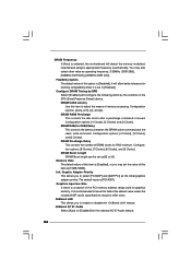
... heatsink when you implement Dual Channel Memory Technology, make sure to perform over-clocking. For audio output, this motherboard supports both stereo and mono modes. BIOS: OS: Audio Jack: Side Speaker / Rear Speaker / Central/Bass / Line In / Front Speaker / Microphone (see CAUTION 7) AMI legal BIOS, Supports "Plug and Play", ACPI 1.1 compliance wake up events, Supports jumperfree, CPU frequency stepless control (only for proper connection. 8. Please check the table on the AGP slot of memory modules on this motherboard...
... heatsink when you implement Dual Channel Memory Technology, make sure to perform over-clocking. For audio output, this motherboard supports both stereo and mono modes. BIOS: OS: Audio Jack: Side Speaker / Rear Speaker / Central/Bass / Line In / Front Speaker / Microphone (see CAUTION 7) AMI legal BIOS, Supports "Plug and Play", ACPI 1.1 compliance wake up events, Supports jumperfree, CPU frequency stepless control (only for proper connection. 8. Please check the table on the AGP slot of memory modules on this motherboard...
User Manual
Page 19
... the SATA hard disk. 2.7 Serial ATA (SATA) Hard Disks Installation This motherboard adopts Intel ICH5 south bridge chipset that supports Serial ATA (SATA) hard disks. STEP 5: Connect the SATA power cable to the instruction on this step. If you to the SATA hard disk. If you need to check and ensure the configuration of the OnBoard IDE Operate Mode option in BIOS setup is complete at this motherboard for internal storage devices. STEP 4: Connect the other end of the second SATA data cable to the motherboard's primary SATA connector (SATA1...
... the SATA hard disk. 2.7 Serial ATA (SATA) Hard Disks Installation This motherboard adopts Intel ICH5 south bridge chipset that supports Serial ATA (SATA) hard disks. STEP 5: Connect the SATA power cable to the instruction on this step. If you to the SATA hard disk. If you need to check and ensure the configuration of the OnBoard IDE Operate Mode option in BIOS setup is complete at this motherboard for internal storage devices. STEP 4: Connect the other end of the second SATA data cable to the motherboard's primary SATA connector (SATA1...
User Manual
Page 20
... PCI features Boot To set up the default system device to locate and load the Operating System Security To set up the security features Chipset To set up the computer. You may not exactly match what you start up the chipset features Exit To exit the current screen or the BIOS SETUP UTILITY Use < > key or < > key to choose among the selections on the menu bar, and then press to enter...
... PCI features Boot To set up the default system device to locate and load the Operating System Security To set up the security features Chipset To set up the computer. You may not exactly match what you start up the chipset features Exit To exit the current screen or the BIOS SETUP UTILITY Use < > key or < > key to choose among the selections on the menu bar, and then press to enter...
User Manual
Page 22
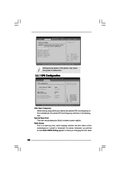
...If it shows "Unlocked", you changing the ratio value 22 CPU Configuration Chipset Configuration ACPI Configuration IDE Configuration PCIPnP Configuration Floppy Configuration SuperIO Configuration USB Configuration Configure CPU Select Screen Select Item Enter Go to allow you will show in this section may cause system to malfunction. CPU Host Frequency While entering setup, BIOS auto detects the present CPU host frequency of this motherboard. Main BIOS SETUP UTILITY Advanced H/W Monitor Boot Security Exit Advanced Settings WARNING : Setting wrong values in below sections may...
...If it shows "Unlocked", you changing the ratio value 22 CPU Configuration Chipset Configuration ACPI Configuration IDE Configuration PCIPnP Configuration Floppy Configuration SuperIO Configuration USB Configuration Configure CPU Select Screen Select Item Enter Go to allow you will show in this section may cause system to malfunction. CPU Host Frequency While entering setup, BIOS auto detects the present CPU host frequency of this motherboard. Main BIOS SETUP UTILITY Advanced H/W Monitor Boot Security Exit Advanced Settings WARNING : Setting wrong values in below sections may...

User Manual
Page 23
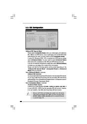
... BIOS SETUP UTILITY Advanced Chipset Configuration Bypass Access [Off] DRAM Frequency [Auto] Flexibility Option [Disabled] Configure DRAM Timing by SPD [Disabled] DRAM CAS# Latency [Auto] DRAM RAS# Precharge [4 Clocks] DRAM RAS# to the core speed of the installed processor. of this motherboard. This should be enabled in order to time the CPU frequency, it shows "Locked", then the item Ratio CMOS Setting will be hidden. CPU Thermal Throttling You may select [Enabled] to enable P4 CPU internal thermal control mechanism to [Auto] if using Microsoft® Windows...
... BIOS SETUP UTILITY Advanced Chipset Configuration Bypass Access [Off] DRAM Frequency [Auto] Flexibility Option [Disabled] Configure DRAM Timing by SPD [Disabled] DRAM CAS# Latency [Auto] DRAM RAS# Precharge [4 Clocks] DRAM RAS# to the core speed of the installed processor. of this motherboard. This should be enabled in order to time the CPU frequency, it shows "Locked", then the item Ratio CMOS Setting will be hidden. CPU Thermal Throttling You may select [Enabled] to enable P4 CPU internal thermal control mechanism to [Auto] if using Microsoft® Windows...
User Manual
Page 24
... This controls the latency between the DRAM active command and the read / write command. Graphics Aperture Size It refers to enable or disable the "OnBoard LAN" feature. Memory Hole The default value of the PCI memory address range used for memory compatibility when it is selected, the motherboard will detect the memory module(s) inserted and assigns appropriate frequency automatically. DRAM Frequency If [Auto] is set to [Enabled]. Flexibility Option The default value of DRAM clocks for the onboard...
... This controls the latency between the DRAM active command and the read / write command. Graphics Aperture Size It refers to enable or disable the "OnBoard LAN" feature. Memory Hole The default value of the PCI memory address range used for memory compatibility when it is selected, the motherboard will detect the memory module(s) inserted and assigns appropriate frequency automatically. DRAM Frequency If [Auto] is set to [Enabled]. Flexibility Option The default value of DRAM clocks for the onboard...
User Manual
Page 26
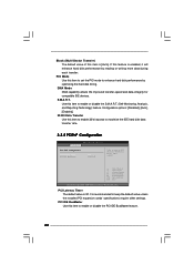
... primary IDE channel or the secondary IDE channel. 3.3.4 IDE Configuration BIOS SETUP UTILITY Advanced IDE Configuration OnBoard IDE Operate Mode OnBoard IDE Controller Primary IDE Master Primary IDE Slave Secondary IDE Master Secondary IDE Slave SATA1 SATA2 [Enhanced Mode] [Both] [Hard Disk] [Not Detected] [Not Detected] [Not Detected] [Not Detected] [Not Detected] Set [Compatible Mode] when both Legacy OS (MS-DOS, Win Me / 98SE) and SATA device are used. When [Enhanced Mode] is used with legacy OS. 26 Set to select between [Pri IDE + SATA] and [SATA + Sec IDE]. Likewise...
... primary IDE channel or the secondary IDE channel. 3.3.4 IDE Configuration BIOS SETUP UTILITY Advanced IDE Configuration OnBoard IDE Operate Mode OnBoard IDE Controller Primary IDE Master Primary IDE Slave Secondary IDE Master Secondary IDE Slave SATA1 SATA2 [Enhanced Mode] [Both] [Hard Disk] [Not Detected] [Not Detected] [Not Detected] [Not Detected] [Not Detected] Set [Compatible Mode] when both Legacy OS (MS-DOS, Win Me / 98SE) and SATA device are used. When [Enhanced Mode] is used with legacy OS. 26 Set to select between [Pri IDE + SATA] and [SATA + Sec IDE]. Likewise...

User Manual
Page 27
... UNIX user, select [Disabled] to select the LBA/Large mode for IDE ARMD (ATAPI Removable Media Device), such as MO. Advanced BIOS SETUP UTILITY Primary IDE Master Device Vendor Size LBA Mode Block Mode PIO Mode Async DMA Ultra DMA S.M.A.R.T. TYPE Use this item to disable the LBA/Large mode. 27 Configuration options: [Not Installed], [Auto], [CD/DVD], and [ARMD]. [Not Installed]: Select [Not Installed] to partition and format the new IDE hard disk drives. This is used for IDE CD/DVD drives. [ARMD...
... UNIX user, select [Disabled] to select the LBA/Large mode for IDE ARMD (ATAPI Removable Media Device), such as MO. Advanced BIOS SETUP UTILITY Primary IDE Master Device Vendor Size LBA Mode Block Mode PIO Mode Async DMA Ultra DMA S.M.A.R.T. TYPE Use this item to disable the LBA/Large mode. 27 Configuration options: [Not Installed], [Auto], [CD/DVD], and [ARMD]. [Not Installed]: Select [Not Installed] to partition and format the new IDE hard disk drives. This is used for IDE CD/DVD drives. [ARMD...
User Manual
Page 28
...Technology) feature. S.M.A.R.T. Configuration options: [Disabled], [Auto], [Enabled]. 32-Bit Data Transfer Use this item is enabled, it will enhance hard disk performance by optimizing the hard disk timing. Block (Multi-Sector Transfer) The default value of this item to enable 32-bit access to maximize the IDE hard disk data transfer rate. 3.3.5 PCIPnP Configuration BIOS SETUP UTILITY Advanced PCI / PnP Configuration PCI Latency Timer PCI IDE BusMaster [32] [Enabled] Value in units of PCI clocks for compatible IDE devices. PIO Mode Use this feature is [Auto]. DMA Mode...
...Technology) feature. S.M.A.R.T. Configuration options: [Disabled], [Auto], [Enabled]. 32-Bit Data Transfer Use this item is enabled, it will enhance hard disk performance by optimizing the hard disk timing. Block (Multi-Sector Transfer) The default value of this item to enable 32-bit access to maximize the IDE hard disk data transfer rate. 3.3.5 PCIPnP Configuration BIOS SETUP UTILITY Advanced PCI / PnP Configuration PCI Latency Timer PCI IDE BusMaster [32] [Enabled] Value in units of PCI clocks for compatible IDE devices. PIO Mode Use this feature is [Auto]. DMA Mode...
User Manual
Page 29
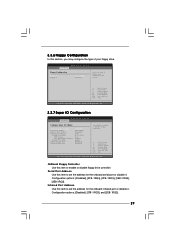
... Advanced BIOS SETUP UTILITY Configure Super IO Chipset OnBoard Floppy Controller Serial Port Address Infrared Port Address Parallel Port Address Parallel Port Mode EPP Version ECP Mode DMA Channel Parallel Port IRQ OnBoard Game Port OnBoard MIDI Port [Enabled] [3F8 / IRQ4] [Disabled] [378] [ECP + EPP] [1.9] [DMA3] [IRQ7] [Enabled] [Disabled] Allow BIOS to Enable or Disable Floppy Controller. +F1 F9 F10 ESC Select Screen Select Item Change Option General Help Load Defaults Save and Exit Exit v02.54 (C) Copyright 1985-2003, American Megatrends, Inc. OnBoard Floppy Controller Use this...
... Advanced BIOS SETUP UTILITY Configure Super IO Chipset OnBoard Floppy Controller Serial Port Address Infrared Port Address Parallel Port Address Parallel Port Mode EPP Version ECP Mode DMA Channel Parallel Port IRQ OnBoard Game Port OnBoard MIDI Port [Enabled] [3F8 / IRQ4] [Disabled] [378] [ECP + EPP] [1.9] [DMA3] [IRQ7] [Enabled] [Disabled] Allow BIOS to Enable or Disable Floppy Controller. +F1 F9 F10 ESC Select Screen Select Item Change Option General Help Load Defaults Save and Exit Exit v02.54 (C) Copyright 1985-2003, American Megatrends, Inc. OnBoard Floppy Controller Use this...

User Manual
Page 31
...of USB controller. if there is no USB device connected, "Auto" option will start to enable or disable the use of the CPU temperature, motherboard temperature, CPU fan speed, chassis fan speed, and the critical voltage. Legacy USB Support Use this item to auto-detect; 3.3.8 USB Configuration Advanced BIOS SETUP UTILITY USB Configuration USB Devices Enabled : None USB Controller USB 2.0 Support Legacy USB Support [Enabled] [Enabled] [Disabled] To enable or disable the onboard USB controllers. +F1 F9 F10 ESC Select Screen Select Item Change Option General Help Load Defaults Save...
...of USB controller. if there is no USB device connected, "Auto" option will start to enable or disable the use of the CPU temperature, motherboard temperature, CPU fan speed, chassis fan speed, and the critical voltage. Legacy USB Support Use this item to auto-detect; 3.3.8 USB Configuration Advanced BIOS SETUP UTILITY USB Configuration USB Devices Enabled : None USB Controller USB 2.0 Support Legacy USB Support [Enabled] [Enabled] [Disabled] To enable or disable the onboard USB controllers. +F1 F9 F10 ESC Select Screen Select Item Change Option General Help Load Defaults Save...

User Manual
Page 32
Main Advanced BIOS SETUP UTILITY H/W Monitor Boot Security Exit Boot Settings Boot Settings Configuration 1st Boot Device 2nd Boot Device 3rd Boot Device Hard Disk Drives Removable Drives CD/DVD Drives [1st Floppy Device] [2nd Floppy Device] [3rd Floppy Device] Configure Settings during System Boot. Boot Up Num-Lock If this item to enable or disable the Boot From Network feature. Boot From Network Use this item is set to [On], it will automatically activate the Numeric Lock function after boot-up. 32 3.5 Boot Screen In this section, it will display the available devices on...
Main Advanced BIOS SETUP UTILITY H/W Monitor Boot Security Exit Boot Settings Boot Settings Configuration 1st Boot Device 2nd Boot Device 3rd Boot Device Hard Disk Drives Removable Drives CD/DVD Drives [1st Floppy Device] [2nd Floppy Device] [3rd Floppy Device] Configure Settings during System Boot. Boot Up Num-Lock If this item to enable or disable the Boot From Network feature. Boot From Network Use this item is set to [On], it will automatically activate the Numeric Lock function after boot-up. 32 3.5 Boot Screen In this section, it will display the available devices on...
User Manual
Page 33
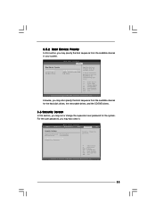
... For the user password, you may also clear it. BIOS SETUP UTILITY Main Advanced H/W Monitor Boot Security Exit Security Settings Supervisor Password : Not Installed User Password : Not Installed Change Supervisor Password Change User Password Install or Change the password. 3.5.2 Boot Device Priority In this section, you may set or change the supervisor/user password for the hard disk drives, the removable drives, and the CD/DVD drives. 3.6 Security Screen In this section, you may specify the boot sequence from the available devices in the corresponding type menu. +F1...
... For the user password, you may also clear it. BIOS SETUP UTILITY Main Advanced H/W Monitor Boot Security Exit Security Settings Supervisor Password : Not Installed User Password : Not Installed Change Supervisor Password Change User Password Install or Change the password. 3.5.2 Boot Device Priority In this section, you may set or change the supervisor/user password for the hard disk drives, the removable drives, and the CD/DVD drives. 3.6 Security Screen In this section, you may specify the boot sequence from the available devices in the corresponding type menu. +F1...
User Manual
Page 35
... devices. 4.2.3 Utilities Menu The Utilities Menu shows the applications software that enhance the motherboard features. 4.2.1 Running The Support CD To begin using the support CD, insert the CD into your own PC system step by step. Please install the necessary drivers to install your CD-ROM drive. You can find the file through the following path: ..\ MPEGAV \ AVSEQ01.DAT To see this chapter for more about ASRock...
... devices. 4.2.3 Utilities Menu The Utilities Menu shows the applications software that enhance the motherboard features. 4.2.1 Running The Support CD To begin using the support CD, insert the CD into your own PC system step by step. Please install the necessary drivers to install your CD-ROM drive. You can find the file through the following path: ..\ MPEGAV \ AVSEQ01.DAT To see this chapter for more about ASRock...
Quick Installation Guide
Page 2
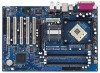
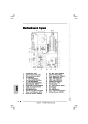
...Secondary Serial ATA Connector (SATA2) 13 Primary Serial ATA Connector (SATA1) 14 Chassis Fan Connector (CHA_FAN1) 15 Clear CMOS Jumper (CLRCMOS0) 16 System Panel Header (PANEL1) 17 Chassis Speaker Header (SPEAKER 1) 18 Infrared Module Header (IR1) 19 USB 2.0 Header (USB67, Blue) 20 USB 2.0 Header (USB45, Blue) 21 Floppy Connector (FLOPPY1) 22 Game Connector (GAME1) 23 PCI Slots (PCI1- 5) 24 Front Panel Audio Header (AUDIO1) 25 JR1 / JL1 Jumpers 26 BIOS FWH Chip 27 North Bridge Controller 28 Internal Audio Connector: CD1 (Black) 29 ATX Power Connector (ATXPWR1) 2 ASRock P4i65PE Motherboard...
...Secondary Serial ATA Connector (SATA2) 13 Primary Serial ATA Connector (SATA1) 14 Chassis Fan Connector (CHA_FAN1) 15 Clear CMOS Jumper (CLRCMOS0) 16 System Panel Header (PANEL1) 17 Chassis Speaker Header (SPEAKER 1) 18 Infrared Module Header (IR1) 19 USB 2.0 Header (USB67, Blue) 20 USB 2.0 Header (USB45, Blue) 21 Floppy Connector (FLOPPY1) 22 Game Connector (GAME1) 23 PCI Slots (PCI1- 5) 24 Front Panel Audio Header (AUDIO1) 25 JR1 / JL1 Jumpers 26 BIOS FWH Chip 27 North Bridge Controller 28 Internal Audio Connector: CD1 (Black) 29 ATX Power Connector (ATXPWR1) 2 ASRock P4i65PE Motherboard...
Quick Installation Guide
Page 4
... the user manual presented in the Support CD. Because the motherboard specifications and the BIOS software might be updated, the content of the motherboard can be subject to quality and endurance. In case any modifications of the motherboard and step-bystep installation guide. ASRock website http://www.asrock.com 1.1 Package Contents ASRock P4i65PE Motherboard (ATX Form Factor: 12.0-in x 8.2-in Floppy Drive One Serial ATA (SATA) Data Cable One Serial ATA (SATA) HDD Power Cable (Optional) One ASRock 8CH I/O Shield 4 ASRock P4i65PE Motherboard English...
... the user manual presented in the Support CD. Because the motherboard specifications and the BIOS software might be updated, the content of the motherboard can be subject to quality and endurance. In case any modifications of the motherboard and step-bystep installation guide. ASRock website http://www.asrock.com 1.1 Package Contents ASRock P4i65PE Motherboard (ATX Form Factor: 12.0-in x 8.2-in Floppy Drive One Serial ATA (SATA) Data Cable One Serial ATA (SATA) HDD Power Cable (Optional) One ASRock 8CH I/O Shield 4 ASRock P4i65PE Motherboard English...
Quick Installation Guide
Page 6
... "User Manual" in the Support CD. 2. BIOS: OS: Audio Jack: Side Speaker / Rear Speaker / Central/Bass / Line In / Front Speaker / Microphone (see CAUTION 7) AMI legal BIOS, Supports "Plug and Play", ACPI 1.1 compliance wake up events, Supports jumperfree, CPU frequency stepless control (only for the memory support frequency and its corresponding CPU FSB frequency. About the setting of "Hyper Threading Technology", please check page 23 of the system or damage the CPU. 6 ASRock P4i65PE Motherboard English Before you install the...
... "User Manual" in the Support CD. 2. BIOS: OS: Audio Jack: Side Speaker / Rear Speaker / Central/Bass / Line In / Front Speaker / Microphone (see CAUTION 7) AMI legal BIOS, Supports "Plug and Play", ACPI 1.1 compliance wake up events, Supports jumperfree, CPU frequency stepless control (only for the memory support frequency and its corresponding CPU FSB frequency. About the setting of "Hyper Threading Technology", please check page 23 of the system or damage the CPU. 6 ASRock P4i65PE Motherboard English Before you install the...
Quick Installation Guide
Page 14
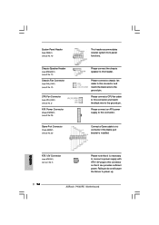
Connect a Game cable to this connector if the Game port bracket is necessary to connect a power supply with ATX 12V plug to this header. Please connect an ATX power supply to power up. 14 ASRock P4i65PE Motherboard Failing to do so will cause the failure to this connector and match the black wire to the ground pin. Please connect a CPU fan cable to this connector. Please connect a chassis fan cable to this connector so that it can provides sufficient power. English ATX 12V Connector (4-pin ATX12V1) (see...
Connect a Game cable to this connector if the Game port bracket is necessary to connect a power supply with ATX 12V plug to this header. Please connect an ATX power supply to power up. 14 ASRock P4i65PE Motherboard Failing to do so will cause the failure to this connector and match the black wire to the ground pin. Please connect a CPU fan cable to this connector. Please connect a chassis fan cable to this connector so that it can provides sufficient power. English ATX 12V Connector (4-pin ATX12V1) (see...
Quick Installation Guide
Page 16
... 16 ASRock P4i65PE Motherboard English To see this demo program, you start up the computer, please press during the Power-On-Self-Test (POST) to install your own PC system. It will enhance motherboard features. If you a step-by pressing + + , or pressing the reset button on the file "ASSETUP.EXE" from the "BIN" folder in your CD-ROM drive. To begin using the Support CD...
... 16 ASRock P4i65PE Motherboard English To see this demo program, you start up the computer, please press during the Power-On-Self-Test (POST) to install your own PC system. It will enhance motherboard features. If you a step-by pressing + + , or pressing the reset button on the file "ASSETUP.EXE" from the "BIN" folder in your CD-ROM drive. To begin using the Support CD...


