
User Manual
Page 3
... 5 1.1 Package Contents 5 1.2 Specifications 6 1.3 Motherboard Layout 8 1.4 ASRock 8CH I/O 9 2 Installation 10 Pre-installation Precautions 10 2.1 CPU Installation 11 2.2 Installation of CPU Fan and Heatsink 11 2.3 Installation of Memory Modules (DIMM 12 2.4 Expansion Slots (PCI and AGP Slots 14 2.5 Jumpers Setup 15 2.6 Onboard Headers and Connectors 16 2.7 Serial ATA (SATA) Hard Disks Installation 19 3 BIOS...
... 5 1.1 Package Contents 5 1.2 Specifications 6 1.3 Motherboard Layout 8 1.4 ASRock 8CH I/O 9 2 Installation 10 Pre-installation Precautions 10 2.1 CPU Installation 11 2.2 Installation of CPU Fan and Heatsink 11 2.3 Installation of Memory Modules (DIMM 12 2.4 Expansion Slots (PCI and AGP Slots 14 2.5 Jumpers Setup 15 2.6 Onboard Headers and Connectors 16 2.7 Serial ATA (SATA) Hard Disks Installation 19 3 BIOS...
User Manual
Page 5
...8.2-in, 30.5 cm x 20.8 cm) ASRock P4i65PE Quick Installation Guide ASRock P4i65PE Support CD One 80-conductor Ultra ATA 66/100 IDE Ribbon Cable One Ribbon Cable for purchasing ASRock P4i65PE motherboard, a reliable motherboard produced under ASRock's consistently stringent quality control. Because the motherboard ... you for a 3.5-in Floppy Drive One Serial ATA (SATA) Data Cable One Serial ATA (SATA) HDD Power Cable (Optional) One ASRock 8CH I/O 5 It delivers excellent performance with robust design conforming to ASRock's commitment to change without further notice. You may find...
...8.2-in, 30.5 cm x 20.8 cm) ASRock P4i65PE Quick Installation Guide ASRock P4i65PE Support CD One 80-conductor Ultra ATA 66/100 IDE Ribbon Cable One Ribbon Cable for purchasing ASRock P4i65PE motherboard, a reliable motherboard produced under ASRock's consistently stringent quality control. Because the motherboard ... you for a 3.5-in Floppy Drive One Serial ATA (SATA) Data Cable One Serial ATA (SATA) HDD Power Cable (Optional) One ASRock 8CH I/O 5 It delivers excellent performance with robust design conforming to ASRock's commitment to change without further notice. You may find...

User Manual
Page 6
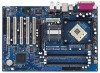
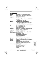
... Bridge: Intel® 865PE chipset, FSB @ 800 / 533 / 400MHz, supports Hyper-Threading Technology (see CAUTION 1) South Bridge: Intel® ICH5, supports SATA 1.5Gb/s Memory: 4 DDR DIMM Slots: DDR1, DDR2, DDR3, and DDR4 4 DDR DIMM Slots Supports PC3200 (DDR400) / PC2700 (DDR333) / PC2100 (...3u (10/100 Ethernet), supports Wake-On-LAN Hardware Monitor: CPU temperature sensing, Chassis temperature sensing, CPU overheat shutdown to protect CPU life (ASRock U-COP)(see CAUTION 4), CPU fan tachometer, Chassis fan tachometer, Voltage monitoring: +12V, +5V, +3.3V, Vcore PCI slots: 5 PCI...
... Bridge: Intel® 865PE chipset, FSB @ 800 / 533 / 400MHz, supports Hyper-Threading Technology (see CAUTION 1) South Bridge: Intel® ICH5, supports SATA 1.5Gb/s Memory: 4 DDR DIMM Slots: DDR1, DDR2, DDR3, and DDR4 4 DDR DIMM Slots Supports PC3200 (DDR400) / PC2700 (DDR333) / PC2100 (...3u (10/100 Ethernet), supports Wake-On-LAN Hardware Monitor: CPU temperature sensing, Chassis temperature sensing, CPU overheat shutdown to protect CPU life (ASRock U-COP)(see CAUTION 4), CPU fan tachometer, Chassis fan tachometer, Voltage monitoring: +12V, +5V, +3.3V, Vcore PCI slots: 5 PCI...

User Manual
Page 16
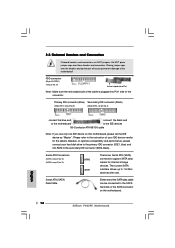
... p.8 No. 21) Pin1 FLOPPY1 the red-striped side to the SATA hard disk or the SATA connector on this motherboard, please set the IDE device as "Master". Serial ATA (SATA) Data Cable Either end of the SATA data cable can be connected to Pin1 Note: Make sure the red...on the motherboard. 16 2.6 Onboard Headers and Connectors Onboard headers and connectors are NOT jumpers. Please refer to 1.5 Gb/s data transfer rate. The current SATA interface allows up to the instruction of the motherboard! Serial ATA Connectors (SATA1: see p.8 No. 13) (SATA2: see p.8 No. 8) PIN1 IDE1...
... p.8 No. 21) Pin1 FLOPPY1 the red-striped side to the SATA hard disk or the SATA connector on this motherboard, please set the IDE device as "Master". Serial ATA (SATA) Data Cable Either end of the SATA data cable can be connected to Pin1 Note: Make sure the red...on the motherboard. 16 2.6 Onboard Headers and Connectors Onboard headers and connectors are NOT jumpers. Please refer to 1.5 Gb/s data transfer rate. The current SATA interface allows up to the instruction of the motherboard! Serial ATA Connectors (SATA1: see p.8 No. 13) (SATA2: see p.8 No. 8) PIN1 IDE1...

User Manual
Page 17
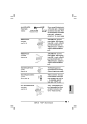
... DVD-ROM, TV tuner card, or MPEG card. USB 2.0 Header (9-pin USB67) (see p.8, No. 20) USB_PWR P-5 P+5 GND DUMMY 1 GND P+4 P-4 USB_PWR ASRock 8CH I /O provides you 4 ready-to -use USB 2.0 ports on the drive. Infrared Module Header (5-pin IR1) (see p.8, No. 24) GND +5VA BACKOUT-R ...) (see p.8, No. 19) USB_PWR P-6 P+6 GND DUMMY 1 GND P+7 P-7 USB_PWR ASRock 8CH I /OTM provides you 4 ready-to -use USB 2.0 ports on the rear panel. O U T- Serial ATA (SATA) Power Cable (Optional) connect to the SATA HDD power connector connect to the power supply Please connect the black end of...
... DVD-ROM, TV tuner card, or MPEG card. USB 2.0 Header (9-pin USB67) (see p.8, No. 20) USB_PWR P-5 P+5 GND DUMMY 1 GND P+4 P-4 USB_PWR ASRock 8CH I /O provides you 4 ready-to -use USB 2.0 ports on the drive. Infrared Module Header (5-pin IR1) (see p.8, No. 24) GND +5VA BACKOUT-R ...) (see p.8, No. 19) USB_PWR P-6 P+6 GND DUMMY 1 GND P+7 P-7 USB_PWR ASRock 8CH I /OTM provides you 4 ready-to -use USB 2.0 ports on the rear panel. O U T- Serial ATA (SATA) Power Cable (Optional) connect to the SATA HDD power connector connect to the power supply Please connect the black end of...
User Manual
Page 19
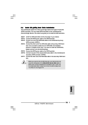
... steps. If you just want to install two SATA HDDs, please continue to the motherboard's primary SATA connector (SATA1). STEP 5: Connect the SATA power cable to the condition of your system. STEP 1: Install the SATA hard disks into the SATA hard disk, you to the instruction on this step...drive bays of your chassis. You may install SATA hard disks on page 26. 19 STEP 2: Connect the SATA power cable to the motherboard's secondary SATA connector (SATA2). STEP 6: Connect one end of the SATA data cable to the secondary SATA hard disk. For the configuration details, please refer...
... steps. If you just want to install two SATA HDDs, please continue to the motherboard's primary SATA connector (SATA1). STEP 5: Connect the SATA power cable to the condition of your system. STEP 1: Install the SATA hard disks into the SATA hard disk, you to the instruction on this step...drive bays of your chassis. You may install SATA hard disks on page 26. 19 STEP 2: Connect the SATA power cable to the motherboard's secondary SATA connector (SATA2). STEP 6: Connect one end of the SATA data cable to the secondary SATA hard disk. For the configuration details, please refer...
User Manual
Page 26
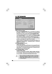
...[Not Detected] [Not Detected] [Not Detected] [Not Detected] Set [Compatible Mode] when both Legacy OS (MS-DOS, Win Me / 98SE) and SATA device are used. OnBoard IDE Operate Mode Please select [Compatible Mode] when you also need to select [Enhanced Mode] while native OS is installed into... following options will not work . Configuration options: [Disabled], [Primary], [Secondary], [Both]. When [Compatible Mode] is installed into IDE HDD and SATA devices are used with legacy OS. 26 If native OS (Windows 2000 / XP) is selected Combined Mode Option It allows you selected. You also...
...[Not Detected] [Not Detected] [Not Detected] [Not Detected] Set [Compatible Mode] when both Legacy OS (MS-DOS, Win Me / 98SE) and SATA device are used. OnBoard IDE Operate Mode Please select [Compatible Mode] when you also need to select [Enhanced Mode] while native OS is installed into... following options will not work . Configuration options: [Disabled], [Primary], [Secondary], [Both]. When [Compatible Mode] is installed into IDE HDD and SATA devices are used with legacy OS. 26 If native OS (Windows 2000 / XP) is selected Combined Mode Option It allows you selected. You also...
Quick Installation Guide
Page 4
..., the content of the motherboard can be found in the user manual presented in Floppy Drive One Serial ATA (SATA) Data Cable One Serial ATA (SATA) HDD Power Cable (Optional) One ASRock 8CH I/O Shield 4 ASRock P4i65PE Motherboard English 1. This Quick Installation Guide contains introduction of this manual will be subject to quality and endurance. It...
..., the content of the motherboard can be found in the user manual presented in Floppy Drive One Serial ATA (SATA) Data Cable One Serial ATA (SATA) HDD Power Cable (Optional) One ASRock 8CH I/O Shield 4 ASRock P4i65PE Motherboard English 1. This Quick Installation Guide contains introduction of this manual will be subject to quality and endurance. It...
Quick Installation Guide
Page 5
...Bridge: Intel® 865PE chipset, FSB @ 800 / 533 / 400MHz, supports Hyper-Threading Technology (see CAUTION 1) South Bridge: Intel® ICH5, supports SATA 1.5Gb/s Memory: 4 DDR DIMM Slots: DDR1, DDR2, DDR3, and DDR4 4 DDR DIMM Slots Supports PC3200 (DDR400) / PC2700 (DDR333) / PC2100... USB 2.0 ports on the rear panel, plus two headers to support 4 additional USB 2.0 ports (see CAUTION 6) ASRock 8CH I/O: 1 PS/2 Mouse Port, 1 PS/2 Keyboard Port 1 Serial Port: COM1 1 Parallel Port (ECP/EPP Support) 4 Ready-to-Use USB 2.0 Ports 1 RJ-45 Port English 5 ASRock P4i65PE Motherboard
...Bridge: Intel® 865PE chipset, FSB @ 800 / 533 / 400MHz, supports Hyper-Threading Technology (see CAUTION 1) South Bridge: Intel® ICH5, supports SATA 1.5Gb/s Memory: 4 DDR DIMM Slots: DDR1, DDR2, DDR3, and DDR4 4 DDR DIMM Slots Supports PC3200 (DDR400) / PC2700 (DDR333) / PC2100... USB 2.0 ports on the rear panel, plus two headers to support 4 additional USB 2.0 ports (see CAUTION 6) ASRock 8CH I/O: 1 PS/2 Mouse Port, 1 PS/2 Keyboard Port 1 Serial Port: COM1 1 Parallel Port (ECP/EPP Support) 4 Ready-to-Use USB 2.0 Ports 1 RJ-45 Port English 5 ASRock P4i65PE Motherboard
Quick Installation Guide
Page 12
...) and CD-ROM to the IDE devices 80-Conductor ATA 66/100 cable Note: If you use only one IDE device on the motherboard. 12 ASRock P4i65PE Motherboard English Primary IDE connector (Blue) Secondary IDE connector (Black) (39-pin IDE1, see p.2 No. 9) (39-pin IDE2, see p.2 No. ...12) SATA2 SATA1 These two Serial ATA (SATA) connectors support SATA data cables for the details. The current SATA interface allows up to the instruction of the motherboard! Serial ATA Connectors (SATA1: see p.2 No. 13) (SATA2: see p.2 No. ...
...) and CD-ROM to the IDE devices 80-Conductor ATA 66/100 cable Note: If you use only one IDE device on the motherboard. 12 ASRock P4i65PE Motherboard English Primary IDE connector (Blue) Secondary IDE connector (Black) (39-pin IDE1, see p.2 No. 9) (39-pin IDE2, see p.2 No. ...12) SATA2 SATA1 These two Serial ATA (SATA) connectors support SATA data cables for the details. The current SATA interface allows up to the instruction of the motherboard! Serial ATA Connectors (SATA1: see p.2 No. 13) (SATA2: see p.2 No. ...
Quick Installation Guide
Page 13
... the I /O panel are not sufficient, this USB 2.0 header is available to support 2 additional USB 2.0 ports. Serial ATA (SATA) Power Cable (Optional) connect to the SATA HDD power connector Please connect the black end of SATA power cable to the power connect to receive stereo audio input from sound sources such as a CD-ROM... (9-pin USB45) (see p.2 No. 18) This header supports an optional wireless transmitting and receiving infrared module. If those USB 2.0 ports on each drive. English 13 ASRock P4i65PE Motherboard
... the I /O panel are not sufficient, this USB 2.0 header is available to support 2 additional USB 2.0 ports. Serial ATA (SATA) Power Cable (Optional) connect to the SATA HDD power connector Please connect the black end of SATA power cable to the power connect to receive stereo audio input from sound sources such as a CD-ROM... (9-pin USB45) (see p.2 No. 18) This header supports an optional wireless transmitting and receiving infrared module. If those USB 2.0 ports on each drive. English 13 ASRock P4i65PE Motherboard
Quick Installation Guide
Page 15
... the other end of the second SATA data cable to the SATA hard disk. STEP 4: Connect the other end of the OnBoard IDE Operate Mode option in the Support CD. 15 ASRock P4i65PE Motherboard English 2.6 Serial ATA (SATA) Hard Disks Installation This motherboard adopts... Intel ICH5 south bridge chipset that supports Serial ATA (SATA) hard disks. STEP 3: Connect one end of the SATA data cable to the motherboard's primary SATA connector (SATA1). STEP 5: Connect the SATA ...
... the other end of the second SATA data cable to the SATA hard disk. STEP 4: Connect the other end of the OnBoard IDE Operate Mode option in the Support CD. 15 ASRock P4i65PE Motherboard English 2.6 Serial ATA (SATA) Hard Disks Installation This motherboard adopts... Intel ICH5 south bridge chipset that supports Serial ATA (SATA) hard disks. STEP 3: Connect one end of the SATA data cable to the motherboard's primary SATA connector (SATA1). STEP 5: Connect the SATA ...
