User Manual
Page 1
All rights reserved. 1 Motherboard P4i45D+ User Manual Version 1.0 Published March 2004 Copyright©2004 ASRock INC.
All rights reserved. 1 Motherboard P4i45D+ User Manual Version 1.0 Published March 2004 Copyright©2004 ASRock INC.

User Manual
Page 3
Boot Menu 28 5. Security Menu 26 3. Advanced Menu 22 2. Power Menu 27 4. Contents 1 Introduction 4 1.1 Package Contents 4 1.2 Specifications 5 1.3 Motherboard Layout 8 1.4 ASRock I/OTM 9 2 Installation 10 2.1 Screw Holes 10 2.2 Pre-installation Precautions 10 2.3 CPU Installation 11 2.4 Installation of Heatsink and CPU fan 11 2.5 Installation of Memory Modules (DIMM ...
Boot Menu 28 5. Security Menu 26 3. Advanced Menu 22 2. Power Menu 27 4. Contents 1 Introduction 4 1.1 Package Contents 4 1.2 Specifications 5 1.3 Motherboard Layout 8 1.4 ASRock I/OTM 9 2 Installation 10 2.1 Screw Holes 10 2.2 Pre-installation Precautions 10 2.3 CPU Installation 11 2.4 Installation of Heatsink and CPU fan 11 2.5 Installation of Memory Modules (DIMM ...

User Manual
Page 4
... manual will be subject to quality and endurance. Chapter 1 Introduction Thank you for new DIY system builders. ASRock website http://www.asrock.com 1.1 Package Contents ASRock P4i45D+ motherboard (ATX form factor: 12.0" x 7.0", 30.5 x 17.8 cm) ASRock P4i45D+ Quick Installation Guide ASRock Intel-Intel Series Support CD 1 cable for IDE devices (1 x ATA 66 / 100) 1 cable for floppy drive (1 x Ribbon...
... manual will be subject to quality and endurance. Chapter 1 Introduction Thank you for new DIY system builders. ASRock website http://www.asrock.com 1.1 Package Contents ASRock P4i45D+ motherboard (ATX form factor: 12.0" x 7.0", 30.5 x 17.8 cm) ASRock P4i45D+ Quick Installation Guide ASRock Intel-Intel Series Support CD 1 cable for IDE devices (1 x ATA 66 / 100) 1 cable for floppy drive (1 x Ribbon...

User Manual
Page 6
.... To improve heat dissipation, remember to the NOTE on P4i45D+'s AGP slot! BIOS: OS: AMI legal BIOS; Supports "Plug and Play"; ACPI 1.1 compliance wake up events; SMBIOS 2.3.1 support; Please check if the CPU fan on the motherboard functions properly before you install the PC system. 4. Supports... the system. It may cause the instability of the system or damage the CPU and the motherboard. 6 When the CPU frequency of "User Manual" in the Support CD. 3. Although P4i45D+ offers stepless control, it is set to Microsoft® official document at http://www.microsoft....
.... To improve heat dissipation, remember to the NOTE on P4i45D+'s AGP slot! BIOS: OS: AMI legal BIOS; Supports "Plug and Play"; ACPI 1.1 compliance wake up events; SMBIOS 2.3.1 support; Please check if the CPU fan on the motherboard functions properly before you install the PC system. 4. Supports... the system. It may cause the instability of the system or damage the CPU and the motherboard. 6 When the CPU frequency of "User Manual" in the Support CD. 3. Although P4i45D+ offers stepless control, it is set to Microsoft® official document at http://www.microsoft....

User Manual
Page 7
... SINGLE SIDE SINGLE SIDE SINGLE SIDE SINGLE SIDE SINGLE SIDE SINGLE SIDE DOUBLE SIDE SINGLE SIDE Since the memory types are changing rapidly, Please visit ASRock website (http://www.asrock.com/support/index.htm) for P4i45D+ motherboard. NOTE The Recommended Memory Modules lists for the latest recommended memory support list. 7
... SINGLE SIDE SINGLE SIDE SINGLE SIDE SINGLE SIDE SINGLE SIDE SINGLE SIDE DOUBLE SIDE SINGLE SIDE Since the memory types are changing rapidly, Please visit ASRock website (http://www.asrock.com/support/index.htm) for P4i45D+ motherboard. NOTE The Recommended Memory Modules lists for the latest recommended memory support list. 7

User Manual
Page 8
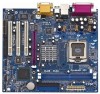
1.3 Motherboard Layout 1 23 4 56 7 17.8cm (7.0 in) PS/2 Mouse PS/2 Keyboard 1 PS2_USB_PWR1 CPU_FAN1 COM1 mPGA478B DDR 1 (64/72 bit, 184-pin module) DDR2 (64/72 bit, ... JR1 JL1 23 22 AUDIO CODEC IDE2 IDE1 Intel 845D Chipsets 8 9 Prescott 800 01 23 CMOS Battery AGP1 10 CLRCMOS0 11 PCI 1 21 PCI LAN P4i45D+ Intel 12 ICH2 20 Super I/O PCI 2 PCI 3 USB45 1 13 FSB 800 DDR400 14 2MB 19 BIOS PCI 4 FLOPPY1 PANEL 1 USB2.0 5.1CH 1 IR1 CHA_FAN1 PLED PWRBTN...
1.3 Motherboard Layout 1 23 4 56 7 17.8cm (7.0 in) PS/2 Mouse PS/2 Keyboard 1 PS2_USB_PWR1 CPU_FAN1 COM1 mPGA478B DDR 1 (64/72 bit, 184-pin module) DDR2 (64/72 bit, ... JR1 JL1 23 22 AUDIO CODEC IDE2 IDE1 Intel 845D Chipsets 8 9 Prescott 800 01 23 CMOS Battery AGP1 10 CLRCMOS0 11 PCI 1 21 PCI LAN P4i45D+ Intel 12 ICH2 20 Super I/O PCI 2 PCI 3 USB45 1 13 FSB 800 DDR400 14 2MB 19 BIOS PCI 4 FLOPPY1 PANEL 1 USB2.0 5.1CH 1 IR1 CHA_FAN1 PLED PWRBTN...
User Manual
Page 10
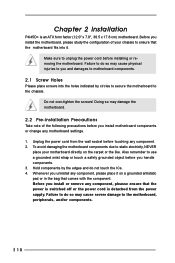
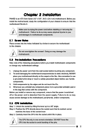
... power is switched off or the power cord is an ATX form factor (12.0" x 7.0", 30.5 x 17.8 cm) motherboard. Before you install the motherboard, please study the configuration of the following precautions before touching any component, please place it . Doing so may cause physical injuries... Failure to do so may damage the motherboard. 2.2 Pre-installation Precautions Take note of your motherboard directly on a grounded antistatic pad or in the bag that comes with the component. Do not over-tighten the screws! Chapter 2 Installation P4i45D+ is detached from the wall socket before...
... power is switched off or the power cord is an ATX form factor (12.0" x 7.0", 30.5 x 17.8 cm) motherboard. Before you install the motherboard, please study the configuration of the following precautions before touching any component, please place it . Doing so may cause physical injuries... Failure to do so may damage the motherboard. 2.2 Pre-installation Precautions Take note of your motherboard directly on a grounded antistatic pad or in the bag that comes with the component. Do not over-tighten the screws! Chapter 2 Installation P4i45D+ is detached from the wall socket before...
User Manual
Page 12
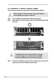
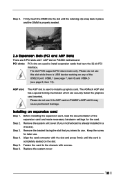
Please make sure to the motherboard and the DIMM if you force the DIMM into the slot until the retaining clips at incorrect orientation. Step 2. Align a DIMM on the slot such ... in place and the DIMM is properly seated. 12 Unlock a DIMM slot by pressing the retaining clips outward. Step 3. 2.5 Installation of Memory Modules (DIMM) This motherboard provides two 184-pin DDR (Double Data Rate) DIMM slots.
Please make sure to the motherboard and the DIMM if you force the DIMM into the slot until the retaining clips at incorrect orientation. Step 2. Align a DIMM on the slot such ... in place and the DIMM is properly seated. 12 Unlock a DIMM slot by pressing the retaining clips outward. Step 3. 2.5 Installation of Memory Modules (DIMM) This motherboard provides two 184-pin DDR (Double Data Rate) DIMM slots.

User Manual
Page 13
Please read the documentation of the expansion card and make sure that you start the installation. Remove the system unit cover (if your motherboard is unplugged. Step 4. Step 6. Please do not plug a 3.3V AGP card in a chassis). Step 2. Fasten the card to the chassis with...the bracket facing the slot that the power supply is switched off or the power cord is already installed in the AGP slot on this motherboard! The ASRock AGP slot has a special locking mechanism which can securely fasten the graphics card inserted. Installing an expansion card Step 1. Step 5. 2.6 ...
Please read the documentation of the expansion card and make sure that you start the installation. Remove the system unit cover (if your motherboard is unplugged. Step 4. Step 6. Please do not plug a 3.3V AGP card in a chassis). Step 2. Fasten the card to the chassis with...the bracket facing the slot that the power supply is switched off or the power cord is already installed in the AGP slot on this motherboard! The ASRock AGP slot has a special locking mechanism which can securely fasten the graphics card inserted. Installing an expansion card Step 1. Step 5. 2.6 ...
User Manual
Page 15
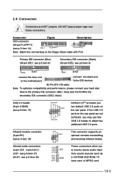
...) (39-pin IDE1, see p.8 item 8) Secondary IDE connector (Black) (39-pin IDE2, see p.8 item 13) USB_PWR P-5 P+5 GND DUMMY 1 GND P+4 P-4 USB_PWR ASRock I/OTM provides you two default USB 2.0 ports on the rear panel. If the USB 2.0 ports on the floppy ribbon cable with Pin1. USB 2.0 header (9-pin ...USB45) (see p.8 item 9) PIN1 IDE1 PIN1 IDE2 connect the blue end to the motherboard connect the black end to the IDE devices 80-Pin ATA 100 cable Note: To optimize compatibility and performance, please connect your hard disk drive...
...) (39-pin IDE1, see p.8 item 8) Secondary IDE connector (Black) (39-pin IDE2, see p.8 item 13) USB_PWR P-5 P+5 GND DUMMY 1 GND P+4 P-4 USB_PWR ASRock I/OTM provides you two default USB 2.0 ports on the rear panel. If the USB 2.0 ports on the floppy ribbon cable with Pin1. USB 2.0 header (9-pin ...USB45) (see p.8 item 9) PIN1 IDE1 PIN1 IDE2 connect the blue end to the motherboard connect the black end to the IDE devices 80-Pin ATA 100 cable Note: To optimize compatibility and performance, please connect your hard disk drive...

User Manual
Page 17
... System EXIT Exits the current menu or the BIOS Setup To access the menu bar items, press the right or left arrow key on the motherboard stores the BIOS Setup Utility. Chapter 3 BIOS Setup 3.1 BIOS Setup Utility This section explains how to use the BIOS Setup Utility to configure your screen...
... System EXIT Exits the current menu or the BIOS Setup To access the menu bar items, press the right or left arrow key on the motherboard stores the BIOS Setup Utility. Chapter 3 BIOS Setup 3.1 BIOS Setup Utility This section explains how to use the BIOS Setup Utility to configure your screen...

User Manual
Page 21
..." is enabled in the Support CD to activate the devices. 4.2.3 Utilities Menu The Utilities Menu shows the applications software that will enhance the motherboard features. 4.2.1 Running The Support CD To begin using the support CD, insert the CD into your CD-ROM drive. Install the necessary drivers... and double click on a specific item then follow the installation wizard to your computer. Chapter 4 Software Support 4.1 Install Operating System This motherboard supports various Microsoft® Windows® operating systems: 98 SE / ME / 2000 / XP. Refer to install it. 21 Because...
..." is enabled in the Support CD to activate the devices. 4.2.3 Utilities Menu The Utilities Menu shows the applications software that will enhance the motherboard features. 4.2.1 Running The Support CD To begin using the support CD, insert the CD into your CD-ROM drive. Install the necessary drivers... and double click on a specific item then follow the installation wizard to your computer. Chapter 4 Software Support 4.1 Install Operating System This motherboard supports various Microsoft® Windows® operating systems: 98 SE / ME / 2000 / XP. Refer to install it. 21 Because...
User Manual
Page 22
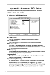
...Auto Disabled Auto [ Setup Help ] to enable or disable the feature of this option is [Disabled]. CPU Ratio Selection: CPU Ratio is selected, the motherboard will introduce you the following BIOS Setup menus: "Advanced," "Security," "Power," "Boot," and "Exit." 1. Flexibility Option The default value of spread ...processor at 3.06 GHz or higher and an operating system that times the frontside bus frequency will equal the core speed of the installed motherboard. Advanced BIOS Setup Menu Main Advanced AMIBIOS SETUP UTILITY - Whether the option is open or locked is set to [Auto] if ...
...Auto Disabled Auto [ Setup Help ] to enable or disable the feature of this option is [Disabled]. CPU Ratio Selection: CPU Ratio is selected, the motherboard will introduce you the following BIOS Setup menus: "Advanced," "Security," "Power," "Boot," and "Exit." 1. Flexibility Option The default value of spread ...processor at 3.06 GHz or higher and an operating system that times the frontside bus frequency will equal the core speed of the installed motherboard. Advanced BIOS Setup Menu Main Advanced AMIBIOS SETUP UTILITY - Whether the option is open or locked is set to [Auto] if ...

User Manual
Page 25
... options: [Disabled], [Primary], [Secondary], [Both]. It allows you may enable both . Configuration options: [Auto], [Disabled], [378], [278]. OnBoard Midi Port: Select address for CPU temperature, Motherboard temperature, CPU fan speed, and critical voltage. Advanced AMIBIOS SETUP UTILITY - Configuration options: [Disabled], [330], [300], [290], [292]. OnBoard IDE: You may check the status...
... options: [Disabled], [Primary], [Secondary], [Both]. It allows you may enable both . Configuration options: [Auto], [Disabled], [378], [278]. OnBoard Midi Port: Select address for CPU temperature, Motherboard temperature, CPU fan speed, and critical voltage. Advanced AMIBIOS SETUP UTILITY - Configuration options: [Disabled], [330], [300], [290], [292]. OnBoard IDE: You may check the status...

User Manual
Page 3
Boot Menu 23 5. Contents 1 Introduction 4 1.1 Package Contents 4 1.2 Specifications 4 1.3 Motherboard Layout 6 1.4 ASRock I/OTM 7 2 Installation 8 2.1 Screw Holes 8 2.2 Pre-installation Precautions 8 2.3 CPU Installation 8 2.4 Installation of Heatsink and CPU fan 9 2.5 ...18 4.1 Installing Operating System 18 4.2 Support CD Information 18 4.2.1 Running Support CD 18 4.2.2 Drivers Menu 18 4.2.3 Utilities Menu 18 4.2.4 ASRock Live Demo Program 18 4.2.5 Contact Information 18 Appendix: Advanced BIOS Setup 19 1. Advanced Menu 19 2. Exit Menu 23 3 Security Menu 21 3....
Boot Menu 23 5. Contents 1 Introduction 4 1.1 Package Contents 4 1.2 Specifications 4 1.3 Motherboard Layout 6 1.4 ASRock I/OTM 7 2 Installation 8 2.1 Screw Holes 8 2.2 Pre-installation Precautions 8 2.3 CPU Installation 8 2.4 Installation of Heatsink and CPU fan 9 2.5 ...18 4.1 Installing Operating System 18 4.2 Support CD Information 18 4.2.1 Running Support CD 18 4.2.2 Drivers Menu 18 4.2.3 Utilities Menu 18 4.2.4 ASRock Live Demo Program 18 4.2.5 Contact Information 18 Appendix: Advanced BIOS Setup 19 1. Advanced Menu 19 2. Exit Menu 23 3 Security Menu 21 3....

User Manual
Page 4
...' reference, the Appendix offers more advanced BIOS setup information. 1.1 Package Contents ASRock P4I45D motherboard (ATX form factor: 12" x 9.6", 30.5 x 24.4 cm) ASRock P4I45D Quick Installation Guide ASRock Intel-Intel Series Support CD 1 Cable for IDE devices (1 x ATA 66... Cable for floppy drive (1 x ribbon cable) 1 ASRock I/O shield 1.2 Specifications Platform: ATX form factor (12" x 9.6", 30.5 x 24.4 cm) CPU: Socket 478 for purchasing ASRock P4I45D motherboard, a reliable motherboard produced under ASRock's consistently stringent quality control. Chapter 1 Introduction Thank you ...
...' reference, the Appendix offers more advanced BIOS setup information. 1.1 Package Contents ASRock P4I45D motherboard (ATX form factor: 12" x 9.6", 30.5 x 24.4 cm) ASRock P4I45D Quick Installation Guide ASRock Intel-Intel Series Support CD 1 Cable for IDE devices (1 x ATA 66... Cable for floppy drive (1 x ribbon cable) 1 ASRock I/O shield 1.2 Specifications Platform: ATX form factor (12" x 9.6", 30.5 x 24.4 cm) CPU: Socket 478 for purchasing ASRock P4I45D motherboard, a reliable motherboard produced under ASRock's consistently stringent quality control. Chapter 1 Introduction Thank you ...

User Manual
Page 5
... system or damage the CPU. 5 Although P4I45D offers stepless control, it is detected, the system will automatically shutdown. Please check if the CPU fan on P4I45D's AGP slot! To improve heat dissipation, ...see page 7 item 7. 5. Frequencies other than the recommended CPU bus frequency may cause permanent damage! 4. AGP slot: USB 2.0: USB 1.1: ASRock I/OTM: BIOS: OS: 1 AGP slot, supports 1.5v, 4X / 2X / 1X AGP card (see CAUTION 3) 2 default USB 2.0 ... PCI slave mode only. [ DO NOT use 3.3V AGP card on the motherboard functions properly before you install the PC system. 2.
... system or damage the CPU. 5 Although P4I45D offers stepless control, it is detected, the system will automatically shutdown. Please check if the CPU fan on P4I45D's AGP slot! To improve heat dissipation, ...see page 7 item 7. 5. Frequencies other than the recommended CPU bus frequency may cause permanent damage! 4. AGP slot: USB 2.0: USB 1.1: ASRock I/OTM: BIOS: OS: 1 AGP slot, supports 1.5v, 4X / 2X / 1X AGP card (see CAUTION 3) 2 default USB 2.0 ... PCI slave mode only. [ DO NOT use 3.3V AGP card on the motherboard functions properly before you install the PC system. 2.
User Manual
Page 8
... P4I45D is detached from the wall socket before touching any component. 2. Failure to do so may cause physical injuries to you install or remove any component, ensure that comes with the component. Unplug the power cord from the power supply. Hold components by lifting the lever up to the motherboard,...fits in one correct orientation. Make sure to use a grounded wrist strap or touch a safety grounded object before installing or removing the motherboard. DO NOT force the CPU into it on the carpet or the like. Also remember to unplug the power cord before you install...
... P4I45D is detached from the wall socket before touching any component. 2. Failure to do so may cause physical injuries to you install or remove any component, ensure that comes with the component. Unplug the power cord from the power supply. Hold components by lifting the lever up to the motherboard,...fits in one correct orientation. Make sure to use a grounded wrist strap or touch a safety grounded object before installing or removing the motherboard. DO NOT force the CPU into it on the carpet or the like. Also remember to unplug the power cord before you install...
User Manual
Page 10
...slot while there is completely seated on any of the expansion card and make necessary hardware settings for later use . The ASRock AGP slot has a special locking mechanism which can securely fasten the graphics card inserted. Before installing the expansion card, read ...item 8) and USB4,5 (see page 6, item 13). Fasten the card to install a graphics card. Please do not use 3.3v AGP card on P4I45D motherboard. Keep the screw for the card. Step 4. It may cause permanent damage. Installing an expansion card Step 1. Step 3. Align the card connector with...
...slot while there is completely seated on any of the expansion card and make necessary hardware settings for later use . The ASRock AGP slot has a special locking mechanism which can securely fasten the graphics card inserted. Before installing the expansion card, read ...item 8) and USB4,5 (see page 6, item 13). Fasten the card to install a graphics card. Please do not use 3.3v AGP card on P4I45D motherboard. Keep the screw for the card. Step 4. It may cause permanent damage. Installing an expansion card Step 1. Step 3. Align the card connector with...

User Manual
Page 11
... (Blue) Secondary IDE connector (Black) (39-pin IDE1, see p.6 item 7) (39-pin IDE2, see p.6 item 8) PIN1 IDE1 PIN1 IDE2 Connect this BLUE end to the motherboard 80-Pin ATA 100 cable Connect this BLACK end to set at (see p.6 item 22) +5VSB (standby) and +5VSB (Default) +5V enable PS/2 or USB...
... (Blue) Secondary IDE connector (Black) (39-pin IDE1, see p.6 item 7) (39-pin IDE2, see p.6 item 8) PIN1 IDE1 PIN1 IDE2 Connect this BLUE end to the motherboard 80-Pin ATA 100 cable Connect this BLACK end to set at (see p.6 item 22) +5VSB (standby) and +5VSB (Default) +5V enable PS/2 or USB...

