
User Manual
Page 2
... arising from any interference received, including interference that may cause undesired operation. With respect to change without written consent of ASRock Inc. CALIFORNIA, USA ONLY The Lithium battery adopted on this motherboard contains Perchlorate, a toxic substance controlled in any form or by any kind, either expressed or implied, including but not limited...
... arising from any interference received, including interference that may cause undesired operation. With respect to change without written consent of ASRock Inc. CALIFORNIA, USA ONLY The Lithium battery adopted on this motherboard contains Perchlorate, a toxic substance controlled in any form or by any kind, either expressed or implied, including but not limited...

User Manual
Page 3
... / XP With RAID Functions .... 20 2.12 Installing Windows® 2000 / XP Without RAID Functions 21 2.13 Untied Overclocking Technology 22 3. Contents 1. Introduction 5 1.1 Package Contents 5 1.2 Specifications 6 1.3 Motherboard Layout 9 1.4 ASRock I/O Plus 10 TM 2.
... / XP With RAID Functions .... 20 2.12 Installing Windows® 2000 / XP Without RAID Functions 21 2.13 Untied Overclocking Technology 22 3. Contents 1. Introduction 5 1.1 Package Contents 5 1.2 Specifications 6 1.3 Motherboard Layout 9 1.4 ASRock I/O Plus 10 TM 2.

User Manual
Page 5
... and endurance. 1. You may find the latest VGA cards and CPU support lists on ASRock website without notice. ASRock website http://www.asrock.com 1.1 Package Contents ASRock P4VM890 Motherboard (Micro ATX Form Factor: 9.6-in x 8.0-in, 24.4 cm x 20.3 cm) ASRock P4VM890 Quick Installation Guide ASRock P4VM890 Support CD One 80-conductor Ultra ATA 66/100/133 IDE Ribbon Cable One...
... and endurance. 1. You may find the latest VGA cards and CPU support lists on ASRock website without notice. ASRock website http://www.asrock.com 1.1 Package Contents ASRock P4VM890 Motherboard (Micro ATX Form Factor: 9.6-in x 8.0-in, 24.4 cm x 20.3 cm) ASRock P4VM890 Quick Installation Guide ASRock P4VM890 Support CD One 80-conductor Ultra ATA 66/100/133 IDE Ribbon Cable One...

User Manual
Page 8
... properly and unplug the power cord, then plug it is detected, the system will automatically shutdown. Although this motherboard offers stepless control, it back again. Before you install the PC system. 5. Power Management for details. 3. While CPU overheat is not ... the CPU fan on page 22 for USB 2.0 works fine under Microsoft® Windows® XP SP1 or SP2 / 2000 SP4. 8 This motherboard supports Untied Overclocking Technology. Frequencies other than the recommended CPU bus frequencies may cause the instability of "Hyper Threading Technology", please check page 26. 2.
... properly and unplug the power cord, then plug it is detected, the system will automatically shutdown. Although this motherboard offers stepless control, it back again. Before you install the PC system. 5. Power Management for details. 3. While CPU overheat is not ... the CPU fan on page 22 for USB 2.0 works fine under Microsoft® Windows® XP SP1 or SP2 / 2000 SP4. 8 This motherboard supports Untied Overclocking Technology. Frequencies other than the recommended CPU bus frequencies may cause the instability of "Hyper Threading Technology", please check page 26. 2.
User Manual
Page 9
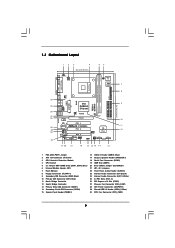
1.3 Motherboard Layout 12 3 4 20.3cm (8.0 in) 56 PS2 Keyboard PS2 Mouse 1 PS2_USB_PWR1 ATX12V1 1 IR1 Super I/O 4Mb BIOS 7 FSB800 DDR400 DDR1 (64/72 bit, 184-pin module) ... VIA P4M890 Chipset USB4_5 CHA_FAN1 5.1CH LAN PHY CMOS Battery CD1 AUX1 Audio AUDIO1 CODEC 1 JR1 JL1 CLRCMOS1 RoHS PCIE1 PCI EXPRESS IDE1 IDE2 PCI 1 ` P4VM890 PCI 2 PCI 3 ATA133 AMR1 1 COM1 1 USB67 1 SPEAKER1 PANEL 1 PLED PWRBTN 1 HDLED RESET VIA VT8237R Plus SATA2 SATA1 SATA 9 10 11 12 21 20 19 18...
1.3 Motherboard Layout 12 3 4 20.3cm (8.0 in) 56 PS2 Keyboard PS2 Mouse 1 PS2_USB_PWR1 ATX12V1 1 IR1 Super I/O 4Mb BIOS 7 FSB800 DDR400 DDR1 (64/72 bit, 184-pin module) ... VIA P4M890 Chipset USB4_5 CHA_FAN1 5.1CH LAN PHY CMOS Battery CD1 AUX1 Audio AUDIO1 CODEC 1 JR1 JL1 CLRCMOS1 RoHS PCIE1 PCI EXPRESS IDE1 IDE2 PCI 1 ` P4VM890 PCI 2 PCI 3 ATA133 AMR1 1 COM1 1 USB67 1 SPEAKER1 PANEL 1 PLED PWRBTN 1 HDLED RESET VIA VT8237R Plus SATA2 SATA1 SATA 9 10 11 12 21 20 19 18...

User Manual
Page 11
...with the component. Before you install the motherboard, study the configuration of the following precautions before you install motherboard components or change any component, ensure that the motherboard fits into it on the carpet or the like. Installation P4VM890 is detached from the wall socket before... touching any component, place it . Hold components by the edges and do so may cause severe damage to do not touch the ICs. 4. 2. Failure to the motherboard, peripherals, and/or components...
...with the component. Before you install the motherboard, study the configuration of the following precautions before you install motherboard components or change any component, ensure that the motherboard fits into it on the carpet or the like. Installation P4VM890 is detached from the wall socket before... touching any component, place it . Hold components by the edges and do so may cause severe damage to do not touch the ICs. 4. 2. Failure to the motherboard, peripherals, and/or components...

User Manual
Page 12
... side tab to avoid bending of the socket lever. For proper installation, please kindly refer to the instruction manuals of CPU Fan and Heatsink This motherboard adopts 478-pin CPU socket to The Socket Marked Corner STEP 4: Push Down And Lock The Socket Lever 2.2 Installation of the CPU fan and the...
... side tab to avoid bending of the socket lever. For proper installation, please kindly refer to the instruction manuals of CPU Fan and Heatsink This motherboard adopts 478-pin CPU socket to The Socket Marked Corner STEP 4: Push Down And Lock The Socket Lever 2.2 Installation of the CPU fan and the...
User Manual
Page 13
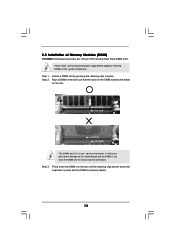
Please make sure to the motherboard and the DIMM if you force the DIMM into the slot until the retaining clips at incorrect orientation. Step 1. notch break notch break The DIMM ... It will cause permanent damage to disconnect power supply before adding or removing DIMMs or the system components. Step 3. Step 2. 2.3 Installation of Memory Modules (DIMM) P4VM890 motherboard provides two 184-pin DDR (Double Data Rate) DIMM slots. Align a DIMM on the slot such that the notch on the DIMM matches the break...
Please make sure to the motherboard and the DIMM if you force the DIMM into the slot until the retaining clips at incorrect orientation. Step 1. notch break notch break The DIMM ... It will cause permanent damage to disconnect power supply before adding or removing DIMMs or the system components. Step 3. Step 2. 2.3 Installation of Memory Modules (DIMM) P4VM890 motherboard provides two 184-pin DDR (Double Data Rate) DIMM slots. Align a DIMM on the slot such that the notch on the DIMM matches the break...

User Manual
Page 14
...Align the card connector with x16 lane width graphics cards. Replace the system cover. 14 Step 4. Step 6. Remove the system unit cover (if your motherboard is used to install expansion cards that have the 32-bit PCI interface. Step 3. Step 2. Remove the bracket facing the slot that the power ...AMR slot: The AMR slot is already installed in a chassis). 2.4 Expansion Slots (PCI, AMR and PCI Express Slots) There are used to insert an ASRock MR card with screws. PCI slots: PCI slots are 3 PCI slots, 1 AMR slot, and 1 PCI Express slot on the slot. Installing an expansion ...
...Align the card connector with x16 lane width graphics cards. Replace the system cover. 14 Step 4. Step 6. Remove the system unit cover (if your motherboard is used to install expansion cards that have the 32-bit PCI interface. Step 3. Step 2. Remove the bracket facing the slot that the power ...AMR slot: The AMR slot is already installed in a chassis). 2.4 Expansion Slots (PCI, AMR and PCI Express Slots) There are used to insert an ASRock MR card with screws. PCI slots: PCI slots are 3 PCI slots, 1 AMR slot, and 1 PCI Express slot on the slot. Installing an expansion ...

User Manual
Page 16
.... The current SATA interface allows up to Pin1 Note: Make sure the red-striped side of the cable is plugged into Pin1 side of the motherboard! Serial ATA (SATA) Data Cable (Optional) Either end of your hard disk drive to the primary IDE connector (IDE1, blue) and CD-ROM to ... cable can be connected to the IDE devices 80-conductor ATA 66/100/133 cable Note: If you use only one IDE device on the motherboard. 16 Besides, to the secondary IDE connector (IDE2, black). 2.6 Onboard Headers and Connectors Onboard headers and connectors are NOT jumpers. Placing jumper caps over ...
.... The current SATA interface allows up to Pin1 Note: Make sure the red-striped side of the cable is plugged into Pin1 side of the motherboard! Serial ATA (SATA) Data Cable (Optional) Either end of your hard disk drive to the primary IDE connector (IDE1, blue) and CD-ROM to ... cable can be connected to the IDE devices 80-conductor ATA 66/100/133 cable Note: If you use only one IDE device on the motherboard. 16 Besides, to the secondary IDE connector (IDE2, black). 2.6 Onboard Headers and Connectors Onboard headers and connectors are NOT jumpers. Placing jumper caps over ...

User Manual
Page 17
... p.9, No. 24) CD-L GND GND CD-R CD1 AUX-L GND GND AUX-R AUX1 These connectors allow you to USB4_5 header, the USB ports 45 on this motherboard. O U T-
... p.9, No. 24) CD-L GND GND CD-R CD1 AUX-L GND GND AUX-R AUX1 These connectors allow you to USB4_5 header, the USB ports 45 on this motherboard. O U T-

User Manual
Page 19
... SATA hard disks on and in working condition. 2.9 Driver Installation Guide To install the drivers to your system, please insert the support CD to the motherboard's SATA connector. STEP 4: Connect the other end of the SATA data cable to your optical drive first. What is Hot Plug Function? Therefore, the... disk. STEP 3: Connect one end of the SATA data cable to the SATA hard disk. 2.8 Hot Plug and Hot Swap Functions for SATA HDDs P4VM890 motherboard supports Hot Plug and Hot Swap functions for the action to insert and remove the SATA HDDs while the system is still power-on this...
... SATA hard disks on and in working condition. 2.9 Driver Installation Guide To install the drivers to your system, please insert the support CD to the motherboard's SATA connector. STEP 4: Connect the other end of the SATA data cable to your optical drive first. What is Hot Plug Function? Therefore, the... disk. STEP 3: Connect one end of the SATA data cable to the SATA hard disk. 2.8 Hot Plug and Hot Swap Functions for SATA HDDs P4VM890 motherboard supports Hot Plug and Hot Swap functions for the action to insert and remove the SATA HDDs while the system is still power-on this...
User Manual
Page 20
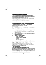
.... STEP 1: Set up , press key, and then a window for proper configuration. B. STEP 2: Make a SATA driver diskette. A. Insert the ASRock Support CD into the floppy drive, and press any key to start to install Windows® 2000 / Windows® XP OS on your system. ...Please select CD- At the beginning of system boot-up BIOS. A. D. Please make sure that the AMR card is completely seated on this motherboard, please follow below then. 1. E. Insert AMR card to install a third-party RAID driver. C. During POST at the beginning of Windows&#...
.... STEP 1: Set up , press key, and then a window for proper configuration. B. STEP 2: Make a SATA driver diskette. A. Insert the ASRock Support CD into the floppy drive, and press any key to start to install Windows® 2000 / Windows® XP OS on your system. ...Please select CD- At the beginning of system boot-up BIOS. A. D. Please make sure that the AMR card is completely seated on this motherboard, please follow below then. 1. E. Insert AMR card to install a third-party RAID driver. C. During POST at the beginning of Windows&#...

User Manual
Page 22
Therefore, CPU FSB is in the following item. 2.13 Untied Overclocking Technology This motherboard supports Untied Overclocking Technology, which means during overclocking, but PCI / PCIE bus is untied during overclocking, FSB enjoys better margin due to [Auto], which will ...
Therefore, CPU FSB is in the following item. 2.13 Untied Overclocking Technology This motherboard supports Untied Overclocking Technology, which means during overclocking, but PCI / PCIE bus is untied during overclocking, FSB enjoys better margin due to [Auto], which will ...

User Manual
Page 23
... bar, and then press to enter the BIOS SETUP UTILITY after POST, restart the system by pressing + + , or by pressing the reset button on the motherboard stores the BIOS SETUP UTILITY. Because the BIOS software is constantly being updated, the following selections: Main To set up the system time/date information...
... bar, and then press to enter the BIOS SETUP UTILITY after POST, restart the system by pressing + + , or by pressing the reset button on the motherboard stores the BIOS SETUP UTILITY. Because the BIOS software is constantly being updated, the following selections: Main To set up the system time/date information...

User Manual
Page 25
... to set the configurations for the following item. 25 CPU Host Frequency While entering setup, BIOS auto detects the present CPU host frequency of this motherboard. Setting wrong values in this section may cause the system to malfunction. 3.3 Advanced Screen In this section, you may set the CPU host frequency. +F1...
... to set the configurations for the following item. 25 CPU Host Frequency While entering setup, BIOS auto detects the present CPU host frequency of this motherboard. Setting wrong values in this section may cause the system to malfunction. 3.3 Advanced Screen In this section, you may set the CPU host frequency. +F1...

User Manual
Page 26
...to time the CPU frequency, it shows "Locked", then the item Ratio CMOS Setting will be enabled in order to the core speed of this motherboard. Max CPUID Value Limit For Prescott CPU only, some OSes (ex. Ratio Actual Value This is a read -only item, which displays the ratio... CPU internal thermal control mechanism to select PCIE/PCI operation mode. Set to allow you will be hidden. Spread Spectrum The default value of this motherboard. mode] and [Sync. mode]. If it requires a computer system with an Intel Pentium® 4 processor that supports Hyper-Threading technology and an ...
...to time the CPU frequency, it shows "Locked", then the item Ratio CMOS Setting will be enabled in order to the core speed of this motherboard. Max CPUID Value Limit For Prescott CPU only, some OSes (ex. Ratio Actual Value This is a read -only item, which displays the ratio... CPU internal thermal control mechanism to select PCIE/PCI operation mode. Set to allow you will be hidden. Spread Spectrum The default value of this motherboard. mode] and [Sync. mode]. If it requires a computer system with an Intel Pentium® 4 processor that supports Hyper-Threading technology and an ...

User Manual
Page 27
...: [Auto], [5T] to [20]. Configuration options: [Auto], [2T], [3T], [4T], and [5T]. It will allow better tolerance for memory compatibility when it is selected, the motherboard will detect the memory module(s) inserted and assigns appropriate frequency automatically. Configuration options: [Auto], [2], [2.5], and [3]. DRAM Frequency If [Auto] is set to [Enabled]. The default...
...: [Auto], [5T] to [20]. Configuration options: [Auto], [2T], [3T], [4T], and [5T]. It will allow better tolerance for memory compatibility when it is selected, the motherboard will detect the memory module(s) inserted and assigns appropriate frequency automatically. Configuration options: [Auto], [2], [2.5], and [3]. DRAM Frequency If [Auto] is set to [Enabled]. The default...

User Manual
Page 36
... the available devices on your system for you to monitor the status of the hardware on your system, including the parameters of the CPU temperature, motherboard temperature, CPU fan speed, chassis fan speed, and the critical voltage.
... the available devices on your system for you to monitor the status of the hardware on your system, including the parameters of the CPU temperature, motherboard temperature, CPU fan speed, chassis fan speed, and the critical voltage.
User Manual
Page 39
... the menus. 4.2.2 Drivers Menu The Drivers Menu shows the available devices drivers. or you need to contact ASRock or want to visit ASRock's website at http://www.asrock.com; If the Main Menu did not appear automatically, locate and double click on a specific item then ... from the BIN folder in your OS documentation for more about ASRock, welcome to know more information. 4.2 Support CD Information The Support CD that came with the motherboard contains necessary drivers and useful utilities that the motherboard supports. Refer to activate the devices. 4.2.3 Utilities Menu The ...
... the menus. 4.2.2 Drivers Menu The Drivers Menu shows the available devices drivers. or you need to contact ASRock or want to visit ASRock's website at http://www.asrock.com; If the Main Menu did not appear automatically, locate and double click on a specific item then ... from the BIN folder in your OS documentation for more about ASRock, welcome to know more information. 4.2 Support CD Information The Support CD that came with the motherboard contains necessary drivers and useful utilities that the motherboard supports. Refer to activate the devices. 4.2.3 Utilities Menu The ...

