
RAID Installation Guide
Page 1
... Installation Guide ...2 1.1 Introduction of RAID ...2 1.2 RAID Configuration Precautions 3 1.3 BIOS Configuration Utility ...3 1.3.1 Enter BIOS Configuration Utility 3 1.3.2 Create Disk Array ...3 1.3.3 Delete Disk Array ...6 1.3.4 Select Boot Array ...6 2. VIA Windows RAID Installation Guide 7 2.1 Create RAID Array ...8 2.2 Delete Disk Array ...10 2.3 Check All ...
... Installation Guide ...2 1.1 Introduction of RAID ...2 1.2 RAID Configuration Precautions 3 1.3 BIOS Configuration Utility ...3 1.3.1 Enter BIOS Configuration Utility 3 1.3.2 Create Disk Array ...3 1.3.3 Delete Disk Array ...6 1.3.4 Select Boot Array ...6 2. VIA Windows RAID Installation Guide 7 2.1 Create RAID Array ...8 2.2 Delete Disk Array ...10 2.3 Check All ...

RAID Installation Guide
Page 2
... that copies and maintains an identical image of data from one drive to a second drive. VIA BIOS RAID Installation Guide You are allowed to VIA RAID installation guide part, including VIA BIOS RAID installation guide and VIA Windows RAID installation guide. 1. RAID 0 (Data Striping) RAID 0 ... you insert two HDDs to VIA SATA connectors and plan to configure RAID functions, please refer to configure RAID functions under BIOS environment. 1.1 Introduction of RAID VIA VT8237 south bridge chipset integrates RAID controller supporting RAID 0, RAID 1, and JBOD functions with two independent ...
... that copies and maintains an identical image of data from one drive to a second drive. VIA BIOS RAID Installation Guide You are allowed to VIA RAID installation guide part, including VIA BIOS RAID installation guide and VIA Windows RAID installation guide. 1. RAID 0 (Data Striping) RAID 0 ... you insert two HDDs to VIA SATA connectors and plan to configure RAID functions, please refer to configure RAID functions under BIOS environment. 1.1 Introduction of RAID VIA VT8237 south bridge chipset integrates RAID controller supporting RAID 0, RAID 1, and JBOD functions with two independent ...

RAID Installation Guide
Page 3
...set is 60GB. 2. Please verify the status of your new RAID array. 1.3 BIOS Configuration Utility 1.3.1 Enter BIOS Configuration Utility After the system powers on, the following information will appear. The main interface of BIOS configuration utility is recommended to use two SATA drives of different sizes, the smaller ...capacity hard disk will be the base storage size. Just highlight the target array mode that you want to enter BIOS configuration utility. For example, if one hard disk has an 80GB storage capacity and the other hard disk has 60GB, the maximum...
...set is 60GB. 2. Please verify the status of your new RAID array. 1.3 BIOS Configuration Utility 1.3.1 Enter BIOS Configuration Utility After the system powers on, the following information will appear. The main interface of BIOS configuration utility is recommended to use two SATA drives of different sizes, the smaller ...capacity hard disk will be the base storage size. Just highlight the target array mode that you want to enter BIOS configuration utility. For example, if one hard disk has an 80GB storage capacity and the other hard disk has 60GB, the maximum...

RAID Installation Guide
Page 4
When using Select Disk Drives method, the channel column will popup. Create RAID 0 If RAID 0 array is "Select Disk Drives". Select "Auto Setup" to allow BIOS to confirm the selection. 3. The block size can also select a block size for the array. create, and press to select the disk drives and create ...
When using Select Disk Drives method, the channel column will popup. Create RAID 0 If RAID 0 array is "Select Disk Drives". Select "Auto Setup" to allow BIOS to confirm the selection. 3. The block size can also select a block size for the array. create, and press to select the disk drives and create ...

User Manual
Page 3
... 23 3.1 Introduction 23 3.1.1 BIOS Menu Bar 23 3.1.2 Navigation Keys 24 3.2 Main Screen 24 3.3 Advanced Screen 25 3.3.1 CPU Configuration 25 3.3.2 Chipset Configuration 27 3.3.3 ACPI Configuration 30 3.3.4 IDE Configuration 31 3.3.5 PCIPnP ... With RAID Functions .... 20 2.12 Installing Windows® 2000 / XP Without RAID Functions 21 2.13 Untied Overclocking Technology 22 3. Introduction 5 1.1 Package Contents 5 1.2 Specifications 6 1.3 Motherboard Layout 9 1.4 ASRock I/O Plus 10 TM 2.
... 23 3.1 Introduction 23 3.1.1 BIOS Menu Bar 23 3.1.2 Navigation Keys 24 3.2 Main Screen 24 3.3 Advanced Screen 25 3.3.1 CPU Configuration 25 3.3.2 Chipset Configuration 27 3.3.3 ACPI Configuration 30 3.3.4 IDE Configuration 31 3.3.5 PCIPnP ... With RAID Functions .... 20 2.12 Installing Windows® 2000 / XP Without RAID Functions 21 2.13 Untied Overclocking Technology 22 3. Introduction 5 1.1 Package Contents 5 1.2 Specifications 6 1.3 Motherboard Layout 9 1.4 ASRock I/O Plus 10 TM 2.

User Manual
Page 5
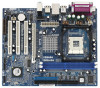
It delivers excellent performance with robust design conforming to ASRock's commitment to BIOS setup and information of the Support CD. Because the motherboard specifications and the BIOS software might be updated, the content of the motherboard and step-bystep guide to ... of this manual will be subject to the hardware installation. ASRock website http://www.asrock.com 1.1 Package Contents ASRock P4VM890 Motherboard (Micro ATX Form Factor: 9.6-in x 8.0-in, 24.4 cm x 20.3 cm) ASRock P4VM890 Quick Installation Guide ASRock P4VM890 Support CD One 80-conductor Ultra ATA 66/100/133 IDE...
It delivers excellent performance with robust design conforming to ASRock's commitment to BIOS setup and information of the Support CD. Because the motherboard specifications and the BIOS software might be updated, the content of the motherboard and step-bystep guide to ... of this manual will be subject to the hardware installation. ASRock website http://www.asrock.com 1.1 Package Contents ASRock P4VM890 Motherboard (Micro ATX Form Factor: 9.6-in x 8.0-in, 24.4 cm x 20.3 cm) ASRock P4VM890 Quick Installation Guide ASRock P4VM890 Support CD One 80-conductor Ultra ATA 66/100/133 IDE...

User Manual
Page 7
... thirdparty overclocking tools. Front panel audio connector - 2 x USB 2.0 headers (support 4 USB 2.0 ports; 2 of your own risk and expense. AMI Legal BIOS - AMBIOS 2.3.1 Support - Voltage Monitoring: +12V, +5V, +3.3V, Vcore - Overclocking may affect your system stability, or even cause damage to the components ... 1.1 Compliance Wake Up Events - Chassis Fan Tachometer - Microsoft® Windows® 2000 / XP compliant - Supports "Plug and Play" - BIOS Feature Support CD Hardware Monitor OS Certifications - 20 pin ATX power connector - 4 pin 12V power connector - CD in header -
... thirdparty overclocking tools. Front panel audio connector - 2 x USB 2.0 headers (support 4 USB 2.0 ports; 2 of your own risk and expense. AMI Legal BIOS - AMBIOS 2.3.1 Support - Voltage Monitoring: +12V, +5V, +3.3V, Vcore - Overclocking may affect your system stability, or even cause damage to the components ... 1.1 Compliance Wake Up Events - Chassis Fan Tachometer - Microsoft® Windows® 2000 / XP compliant - Supports "Plug and Play" - BIOS Feature Support CD Hardware Monitor OS Certifications - 20 pin ATX power connector - 4 pin 12V power connector - CD in header -
User Manual
Page 9
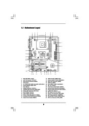
1.3 Motherboard Layout 12 3 4 20.3cm (8.0 in) 56 PS2 Keyboard PS2 Mouse 1 PS2_USB_PWR1 ATX12V1 1 IR1 Super I/O 4Mb BIOS 7 FSB800 DDR400 DDR1 (64/72 bit, 184-pin module) DDR2 (64/72 bit, 184-pin module) FLOPPY1 24.4cm (9.6 in) PGA478 PARALLEL PORT VGA1 8 ... VIA P4M890 Chipset USB4_5 CHA_FAN1 5.1CH LAN PHY CMOS Battery CD1 AUX1 Audio AUDIO1 CODEC 1 JR1 JL1 CLRCMOS1 RoHS PCIE1 PCI EXPRESS IDE1 IDE2 PCI 1 ` P4VM890 PCI 2 PCI 3 ATA133 AMR1 1 COM1 1 USB67 1 SPEAKER1 PANEL 1 PLED PWRBTN 1 HDLED RESET VIA VT8237R Plus SATA2 SATA1 SATA 9 10 11 12 21 20 19 ...
1.3 Motherboard Layout 12 3 4 20.3cm (8.0 in) 56 PS2 Keyboard PS2 Mouse 1 PS2_USB_PWR1 ATX12V1 1 IR1 Super I/O 4Mb BIOS 7 FSB800 DDR400 DDR1 (64/72 bit, 184-pin module) DDR2 (64/72 bit, 184-pin module) FLOPPY1 24.4cm (9.6 in) PGA478 PARALLEL PORT VGA1 8 ... VIA P4M890 Chipset USB4_5 CHA_FAN1 5.1CH LAN PHY CMOS Battery CD1 AUX1 Audio AUDIO1 CODEC 1 JR1 JL1 CLRCMOS1 RoHS PCIE1 PCI EXPRESS IDE1 IDE2 PCI 1 ` P4VM890 PCI 2 PCI 3 ATA133 AMR1 1 COM1 1 USB67 1 SPEAKER1 PANEL 1 PLED PWRBTN 1 HDLED RESET VIA VT8237R Plus SATA2 SATA1 SATA 9 10 11 12 21 20 19 ...
User Manual
Page 20
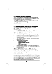
...VIA® RAID driver. Please make sure that the AMR card is completely seated on this motherboard, please follow below then. 1. Insert the ASRock Support CD into the floppy diskette. B. Please select CD- Please refer to the document in the following path in the Support CD: .. \...diskette and copy SATA drivers into your optical drive to boot your system. Install AMR card driver from our support CD to your system. Enter BIOS SETUP UTILITY Advanced screen IDE Configuration. D. The system will start Please insert a floppy diskette into the floppy drive, and press any key. ...
...VIA® RAID driver. Please make sure that the AMR card is completely seated on this motherboard, please follow below then. 1. Insert the ASRock Support CD into the floppy diskette. B. Please select CD- Please refer to the document in the following path in the Support CD: .. \...diskette and copy SATA drivers into your optical drive to boot your system. Install AMR card driver from our support CD to your system. Enter BIOS SETUP UTILITY Advanced screen IDE Configuration. D. The system will start Please insert a floppy diskette into the floppy drive, and press any key. ...

User Manual
Page 21
... IDE HDDs and want to install Windows® 2000 / XP on your SATA HDDs without RAID functions, please follow below steps. Enter BIOS SETUP UTILITY Advanced screen IDE Configuration. If you can start to [RAID] in Windows® environment, please install SATA drivers from the ...Support CD again so that "VIA RAID Tool" will be installed to [non-RAID]. B. A. After setting up BIOS. Then, please set up "SATA Operation Mode" to install Windows® 2000 / XP on your system. 21 STEP 2: Install Windows® 2000 ...
... IDE HDDs and want to install Windows® 2000 / XP on your SATA HDDs without RAID functions, please follow below steps. Enter BIOS SETUP UTILITY Advanced screen IDE Configuration. If you can start to [RAID] in Windows® environment, please install SATA drivers from the ...Support CD again so that "VIA RAID Tool" will be installed to [non-RAID]. B. A. After setting up BIOS. Then, please set up "SATA Operation Mode" to install Windows® 2000 / XP on your system. 21 STEP 2: Install Windows® 2000 ...

User Manual
Page 22
You may set "CPU Host Frequency" option of BIOS setup to [Auto], which means during overclocking, but PCI / PCIE bus is untied during overclocking, FSB enjoys better margin due to the warning on page 7 ...
You may set "CPU Host Frequency" option of BIOS setup to [Auto], which means during overclocking, but PCI / PCIE bus is untied during overclocking, FSB enjoys better margin due to the warning on page 7 ...

User Manual
Page 23
... POST, restart the system by pressing + + , or by turning the system off and then back on the motherboard stores the BIOS SETUP UTILITY. The Flash Memory on . If you wish to configure your screen. 3.1.1 BIOS Menu Bar The top of the screen has a menu bar with its test routines. Because the... is constantly being updated, the following selections: Main To set up the system time/date information Advanced To set up the advanced BIOS features H/W Monitor To display current hardware status Boot To set up the default system device to locate and load the Operating System Security To ...
... POST, restart the system by pressing + + , or by turning the system off and then back on the motherboard stores the BIOS SETUP UTILITY. The Flash Memory on . If you wish to configure your screen. 3.1.1 BIOS Menu Bar The top of the screen has a menu bar with its test routines. Because the... is constantly being updated, the following selections: Main To set up the system time/date information Advanced To set up the advanced BIOS features H/W Monitor To display current hardware status Boot To set up the default system device to locate and load the Operating System Security To ...

User Manual
Page 24
... item to specify the system date. 24 3.1.2 Navigation Keys Please check the following table for all the settings To save changes and exit the BIOS SETUP UTILITY To jump to the Exit Screen or exit the current screen 3.2 Main Screen When you enter the... UTILITY Main Advanced H/W Monitor Boot Security Exit System Overview System Time System Date [16:15:31] [Mon 12/25/2006] BIOS Version : P4VM890 BIOS P1.00 Processor Type : Intel (R) Pentium (R) 4 CPU 2.40GHz Processor Speed : 2400MHz Microcode Update : F33/C Cache Size : 1024KB Total Memory DDR1 DDR2 : 256MB with 64MB shared...
... item to specify the system date. 24 3.1.2 Navigation Keys Please check the following table for all the settings To save changes and exit the BIOS SETUP UTILITY To jump to the Exit Screen or exit the current screen 3.2 Main Screen When you enter the... UTILITY Main Advanced H/W Monitor Boot Security Exit System Overview System Time System Date [16:15:31] [Mon 12/25/2006] BIOS Version : P4VM890 BIOS P1.00 Processor Type : Intel (R) Pentium (R) 4 CPU 2.40GHz Processor Speed : 2400MHz Microcode Update : F33/C Cache Size : 1024KB Total Memory DDR1 DDR2 : 256MB with 64MB shared...

User Manual
Page 25
...Value Max CPUID Value Limit CPU Thermal Throttling Hyper Threading Technology [Auto] [133] [Auto] [Async. CPU Host Frequency While entering setup, BIOS auto detects the present CPU host frequency of this section, you may set the CPU host frequency. +F1 F9 F10 ESC Select Screen ...Select Item Change Option General Help Load Defaults Save and Exit Exit v02.54 (C) Copyright 1985-2003, American Megatrends, Inc. Main BIOS SETUP UTILITY Advanced H/W Monitor Boot Security Exit Advanced Settings WARNING : Setting wrong values in below sections may cause the system to malfunction....
...Value Max CPUID Value Limit CPU Thermal Throttling Hyper Threading Technology [Auto] [133] [Auto] [Async. CPU Host Frequency While entering setup, BIOS auto detects the present CPU host frequency of this section, you may set the CPU host frequency. +F1 F9 F10 ESC Select Screen ...Select Item Change Option General Help Load Defaults Save and Exit Exit v02.54 (C) Copyright 1985-2003, American Megatrends, Inc. Main BIOS SETUP UTILITY Advanced H/W Monitor Boot Security Exit Advanced Settings WARNING : Setting wrong values in below sections may cause the system to malfunction....

User Manual
Page 27
...]. The default value is selected, the motherboard will allow better tolerance for memory compatibility when it is set the timing by dram SPD. 3.3.2 Chipset Configuration BIOS SETUP UTILITY Advanced Chipset Settings DRAM Frequency Flexibility Option DRAM CAS# Latency DRAM Bank Interleave Precharge to Active (Trp) Active to Precharge (Tras) Active to...
...]. The default value is selected, the motherboard will allow better tolerance for memory compatibility when it is set the timing by dram SPD. 3.3.2 Chipset Configuration BIOS SETUP UTILITY Advanced Chipset Settings DRAM Frequency Flexibility Option DRAM CAS# Latency DRAM Bank Interleave Precharge to Active (Trp) Active to Precharge (Tras) Active to...

User Manual
Page 30
... recovers. Select [Auto] will enable this feature if the system supports it. If [Power On] is selected, the AC/Power remains off mode. 3.3.3 ACPI Configuration BIOS SETUP UTILITY Advanced ACPI Configuration Suspend To RAM Restore on AC/Power Loss This allows you to select whether to auto-detect or disable the...
... recovers. Select [Auto] will enable this feature if the system supports it. If [Power On] is selected, the AC/Power remains off mode. 3.3.3 ACPI Configuration BIOS SETUP UTILITY Advanced ACPI Configuration Suspend To RAM Restore on AC/Power Loss This allows you to select whether to auto-detect or disable the...

User Manual
Page 31
3.3.4 IDE Configuration BIOS SETUP UTILITY Advanced IDE Configuration OnBoard IDE Controller SATA Operation Mode [Enabled] [RAID] To enable or disable the onboard IDE controller. Primary IDE Master Primary ... F10 ESC Select Screen Select Item Change Option General Help Load Defaults Save and Exit Exit v02.54 (C) Copyright 1985-2003, American Megatrends, Inc. 31 BIOS SETUP UTILITY Advanced Primary IDE Master Device Vendor Size LBA Mode Block Mode PIO Mode Async DMA Ultra DMA S.M.A.R.T. SATA Operation Mode Use this item...
3.3.4 IDE Configuration BIOS SETUP UTILITY Advanced IDE Configuration OnBoard IDE Controller SATA Operation Mode [Enabled] [RAID] To enable or disable the onboard IDE controller. Primary IDE Master Primary ... F10 ESC Select Screen Select Item Change Option General Help Load Defaults Save and Exit Exit v02.54 (C) Copyright 1985-2003, American Megatrends, Inc. 31 BIOS SETUP UTILITY Advanced Primary IDE Master Device Vendor Size LBA Mode Block Mode PIO Mode Async DMA Ultra DMA S.M.A.R.T. SATA Operation Mode Use this item...

User Manual
Page 32
...-Sector Transfer) The default value of IDE device. [Auto]: Select [Auto] to automatically detect the hard disk drive. After selecting the hard disk information into BIOS, use of this feature is [Auto]. S.M.A.R.T. DMA Mode DMA capability allows the improved transfer-speed and data-integrity for Netware and UNIX user, select [Disabled...
...-Sector Transfer) The default value of IDE device. [Auto]: Select [Auto] to automatically detect the hard disk drive. After selecting the hard disk information into BIOS, use of this feature is [Auto]. S.M.A.R.T. DMA Mode DMA capability allows the improved transfer-speed and data-integrity for Netware and UNIX user, select [Disabled...

User Manual
Page 33
... the type of floppy drive connected to keep the default value unless the installed PCI expansion cards' specifications require other settings. BIOS SETUP UTILITY Advanced Floppy Configuration Floppy A Floppy B [1.44 MB 312"] [Disabled] Select the type of your floppy drive. 3.3.5 PCIPnP Configuration... BIOS SETUP UTILITY Advanced Advanced PCI / PnP Settings PCI Latency Timer PCI IDE BusMaster [32] [Enabled] Value in units of PCI clocks...
... the type of floppy drive connected to keep the default value unless the installed PCI expansion cards' specifications require other settings. BIOS SETUP UTILITY Advanced Floppy Configuration Floppy A Floppy B [1.44 MB 312"] [Disabled] Select the type of your floppy drive. 3.3.5 PCIPnP Configuration... BIOS SETUP UTILITY Advanced Advanced PCI / PnP Settings PCI Latency Timer PCI IDE BusMaster [32] [Enabled] Value in units of PCI clocks...

User Manual
Page 34
... Address Use this item to set the ECP mode DMA channel. Configuration options: [IRQ5] and [IRQ7]. 34 3.3.7 Super IO Configuration BIOS SETUP UTILITY Advanced Configure Super IO Chipset OnBoard Floppy Controller Serial Port Address Infrared Port Address Parallel Port Address Parallel Port Mode EPP Version ECP... Mode DMA Channel Parallel Port IRQ [Enabled] [3F8 / IRQ4] [Disabled] [378] [ECP + EPP] [1.9] [DMA3] [IRQ7] Allow BIOS to set the address for the onboard parallel port or disable it. Parallel Port Mode Use this item to set the EPP version. Infrared Port...
... Address Use this item to set the ECP mode DMA channel. Configuration options: [IRQ5] and [IRQ7]. 34 3.3.7 Super IO Configuration BIOS SETUP UTILITY Advanced Configure Super IO Chipset OnBoard Floppy Controller Serial Port Address Infrared Port Address Parallel Port Address Parallel Port Mode EPP Version ECP... Mode DMA Channel Parallel Port IRQ [Enabled] [3F8 / IRQ4] [Disabled] [378] [ECP + EPP] [1.9] [DMA3] [IRQ7] Allow BIOS to set the address for the onboard parallel port or disable it. Parallel Port Mode Use this item to set the EPP version. Infrared Port...


