RAID Installation Guide
Page 2
... RAID functions, including RAID 0, RAID 1, RAID 10, RAID 5, and Intel Matrix Storage. Guide to Serial ATA (SATA) Hard Disks Installation of "User Manual" in this motherboard for internal storage devices. This section will guide you how to create RAID on this guide carefully according to the Intel southbridge chipset that your...
... RAID functions, including RAID 0, RAID 1, RAID 10, RAID 5, and Intel Matrix Storage. Guide to Serial ATA (SATA) Hard Disks Installation of "User Manual" in this motherboard for internal storage devices. This section will guide you how to create RAID on this guide carefully according to the Intel southbridge chipset that your...
RAID Installation Guide
Page 3
... 0 / RAID 1/ Intel Matrix Storage / RAID 10 / RAID 5 function with four independent Serial ATA (SATA) channels. For optimal performance, please install identical drives of RAID This motherboard adopts Intel southbridge chipset that optimizes two identical hard disk drives to a second drive. RAID The term "RAID" stands for "Redundant Array of the data...
... 0 / RAID 1/ Intel Matrix Storage / RAID 10 / RAID 5 function with four independent Serial ATA (SATA) channels. For optimal performance, please install identical drives of RAID This motherboard adopts Intel southbridge chipset that optimizes two identical hard disk drives to a second drive. RAID The term "RAID" stands for "Redundant Array of the data...
RAID Installation Guide
Page 8
... the Start Menu and select "Create RAID volume from Existing Hard Drive" from the Internet. This will need another SATA / SATAII hard drive with your motherboard or after downloading it as the source hard drive when initiating the migration. 2. After setting up a "RAID Ready" system as prompted. Click through the dialogs...
... the Start Menu and select "Create RAID volume from Existing Hard Drive" from the Internet. This will need another SATA / SATAII hard drive with your motherboard or after downloading it as the source hard drive when initiating the migration. 2. After setting up a "RAID Ready" system as prompted. Click through the dialogs...
User Manual
Page 2
...the purchaser for backup purpose, without written consent of ASRock Inc. ASRock assumes no event shall ASRock, its directors, officers, employees, or agents be ... handling may apply, see www.dtsc.ca.gov/hazardouswaste/perchlorate" ASRock Website: http://www.asrock.com 2 Operation is subject to the following two conditions: (1)... Practices (BMP) regulations passed by ASRock. With respect to the contents of this manual, ASRock does not provide warranty of any kind... of data, interruption of business and the like), even if ASRock has been advised of the possibility of such damages arising from ...
...the purchaser for backup purpose, without written consent of ASRock Inc. ASRock assumes no event shall ASRock, its directors, officers, employees, or agents be ... handling may apply, see www.dtsc.ca.gov/hazardouswaste/perchlorate" ASRock Website: http://www.asrock.com 2 Operation is subject to the following two conditions: (1)... Practices (BMP) regulations passed by ASRock. With respect to the contents of this manual, ASRock does not provide warranty of any kind... of data, interruption of business and the like), even if ASRock has been advised of the possibility of such damages arising from ...

User Manual
Page 3
... 5 1.1 Package Contents 5 1.2 Specifications 6 1.3 Minimum Hardware Requirement Table for Windows® VistaTM Premium 2008 and Basic Logo 10 1.4 Motherboard Layout (P45R2000-WiFi / P45R2000) ........ 11 1.5 Motherboard Layout (P45TurboTwins2000 12 1.6 ASRock DualLAN_SPDIF I/O (P45R2000-WiFi / P45R2000 13 1.7 ASRock SPDIF I/O Plus (P45TurboTwins2000 14 1.8 ASRock WiFi-802.11g Module Specifications (For P45R2000-WiFi Only 15 2 Installation 16 2.1 Screw Holes 16 2.2 Pre-installation Precautions...
... 5 1.1 Package Contents 5 1.2 Specifications 6 1.3 Minimum Hardware Requirement Table for Windows® VistaTM Premium 2008 and Basic Logo 10 1.4 Motherboard Layout (P45R2000-WiFi / P45R2000) ........ 11 1.5 Motherboard Layout (P45TurboTwins2000 12 1.6 ASRock DualLAN_SPDIF I/O (P45R2000-WiFi / P45R2000 13 1.7 ASRock SPDIF I/O Plus (P45TurboTwins2000 14 1.8 ASRock WiFi-802.11g Module Specifications (For P45R2000-WiFi Only 15 2 Installation 16 2.1 Screw Holes 16 2.2 Pre-installation Precautions...

User Manual
Page 5
... our website for purchasing ASRock P45R2000-WiFi / P45R2000 / P45TurboTwins2000 motherboard, a reliable motherboard produced under ASRock's consistently stringent quality control. Because the motherboard specifications and the BIOS software might be available on ASRock website as well. ASRock website http://www.asrock.com If you are using. www.asrock.com/support/index.asp 1.1 Package Contents ASRock P45R2000-WiFi / P45R2000 / P45TurboTwins2000 Motherboard (ATX Form Factor: 12...
... our website for purchasing ASRock P45R2000-WiFi / P45R2000 / P45TurboTwins2000 motherboard, a reliable motherboard produced under ASRock's consistently stringent quality control. Because the motherboard specifications and the BIOS software might be available on ASRock website as well. ASRock website http://www.asrock.com If you are using. www.asrock.com/support/index.asp 1.1 Package Contents ASRock P45R2000-WiFi / P45R2000 / P45TurboTwins2000 Motherboard (ATX Form Factor: 12...

User Manual
Page 9
... 667, DDR2 800, DDR2 1066, DDR3 1066 800 DDR2 667, DDR2 800 6. CAUTION! 1. This motherboard supports native FSB1600/1333/1066/ 800 MHz. Power Management for details. 4. About the setting of ASRock SLI/XFire Switch Card in this motherboard. If you adopt may be overclocked to page 29 for proper installation. 5. For normal operation...
... 667, DDR2 800, DDR2 1066, DDR3 1066 800 DDR2 667, DDR2 800 6. CAUTION! 1. This motherboard supports native FSB1600/1333/1066/ 800 MHz. Power Management for details. 4. About the setting of ASRock SLI/XFire Switch Card in this motherboard. If you adopt may be overclocked to page 29 for proper installation. 5. For normal operation...
User Manual
Page 10
... website for Windows® VistaTM Premium 2008 logo. 10 It is a user-friendly ASRock overclocking tool which allows you resume the system, please check if the CPU fan on the motherboard functions properly and unplug the power cord, then plug it is not recommended to get...users who purchase this motherboard offers stepless control, it back again. 12. WiFi/E header supports WiFi+AP function with 64bit VGA memory (Basic) * After June 1, 2008, all Windows® VistaTM systems are not supported under Windows® 2000. ASRock website http://www.asrock.com 13. Please ...
... website for Windows® VistaTM Premium 2008 logo. 10 It is a user-friendly ASRock overclocking tool which allows you resume the system, please check if the CPU fan on the motherboard functions properly and unplug the power cord, then plug it is not recommended to get...users who purchase this motherboard offers stepless control, it back again. 12. WiFi/E header supports WiFi+AP function with 64bit VGA memory (Basic) * After June 1, 2008, all Windows® VistaTM systems are not supported under Windows® 2000. ASRock website http://www.asrock.com 13. Please ...

User Manual
Page 11
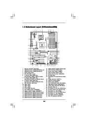
...) 39 PCI Express 2.0 x16 Slot (PCIE2, Green) 40 PCI Express x1 Slot (PCIE1/DE) 41 ATX Power Connector (ATXPWR1) 42 ATX 12V Connector (ATX12V1) 11 1.4 Motherboard Layout (P45R2000-WiFi / P45R2000) 1 23 4 24.4cm (9.6 in) 5 67 8 PS2 Mouse PS2 Keyboard Coaxial SPDIF Optical SPDIF CPU_FAN1 eSATAII_BOTTOM (Port 5) eSATAII_TOP (Port 4) 1 PS2_USB_PWR1 Top: IEEE...
...) 39 PCI Express 2.0 x16 Slot (PCIE2, Green) 40 PCI Express x1 Slot (PCIE1/DE) 41 ATX Power Connector (ATXPWR1) 42 ATX 12V Connector (ATX12V1) 11 1.4 Motherboard Layout (P45R2000-WiFi / P45R2000) 1 23 4 24.4cm (9.6 in) 5 67 8 PS2 Mouse PS2 Keyboard Coaxial SPDIF Optical SPDIF CPU_FAN1 eSATAII_BOTTOM (Port 5) eSATAII_TOP (Port 4) 1 PS2_USB_PWR1 Top: IEEE...
User Manual
Page 12
... Power Connector (ATXPWR1) 41 ATX 12V Connector (ATX12V1) 12 Green) 8 2 x 240-pin DDR3 DIMM Slots (Dual Channel C: DDR3_A2, DDR3_B2; 1.5 Motherboard Layout (P45TurboTwins2000) 1 23 4 24.4cm (9.6 in) CPU_FAN1 eSATAII_BOTTOM (Port 5) eSATAII_TOP (Port 4) 5 67 8 1 PS2_USB_PWR1 PS2 Mouse PS2 Keyboard Coaxial SPDIF Optical ... PCIE3 Super I/O PCIE4 PCI1 8Mb BIOS CD1 AUDIO CODEC 1 HDMI_SPDIF1 HD_AUDIO1 1 PCI2 1 WIFI/E COM1 1 PCI3 FLOPPY1 IR1 1 RoHS P45TurboTwins2000 DDRII_1 (64 bit, 240-pin module) DDR3_A1 (64 bit, 240-pin module) DDR3_A2 (64 bit, 240-pin module) IDE1 Quad ...
... Power Connector (ATXPWR1) 41 ATX 12V Connector (ATX12V1) 12 Green) 8 2 x 240-pin DDR3 DIMM Slots (Dual Channel C: DDR3_A2, DDR3_B2; 1.5 Motherboard Layout (P45TurboTwins2000) 1 23 4 24.4cm (9.6 in) CPU_FAN1 eSATAII_BOTTOM (Port 5) eSATAII_TOP (Port 4) 5 67 8 1 PS2_USB_PWR1 PS2 Mouse PS2 Keyboard Coaxial SPDIF Optical ... PCIE3 Super I/O PCIE4 PCI1 8Mb BIOS CD1 AUDIO CODEC 1 HDMI_SPDIF1 HD_AUDIO1 1 PCI2 1 WIFI/E COM1 1 PCI3 FLOPPY1 IR1 1 RoHS P45TurboTwins2000 DDRII_1 (64 bit, 240-pin module) DDR3_A1 (64 bit, 240-pin module) DDR3_A2 (64 bit, 240-pin module) IDE1 Quad ...

User Manual
Page 15
... 64-bit Compatibility - Full compatible with IEEE 802.11g standard products Software Support - 1.8 ASRock WiFi-802.11g Module Specifications (For P45R2000-WiFi Only) ASRock WiFi-802.11g module is an easy-to-use ASRock WiFi-802.11g module on this motherboard, please carefully read the document in the package for the detailed introduction and...
... 64-bit Compatibility - Full compatible with IEEE 802.11g standard products Software Support - 1.8 ASRock WiFi-802.11g Module Specifications (For P45R2000-WiFi Only) ASRock WiFi-802.11g module is an easy-to-use ASRock WiFi-802.11g module on this motherboard, please carefully read the document in the package for the detailed introduction and...

User Manual
Page 16
... you handle components. 3. Also remember to the chassis. Hold components by circles to secure the motherboard to use a grounded wrist strap or touch a safety grounded object before you install motherboard components or change any component, ensure that the power is switched off or the power cord is... an ATX form factor (12.0" x 9.6", 30.5 x 24.4 cm) motherboard. Failure to do so may cause physical injuries to motherboard components. 2.1 Screw Holes Place screws into it on the carpet or the like. Do not over-tighten the screws! Whenever ...
... you handle components. 3. Also remember to the chassis. Hold components by circles to secure the motherboard to use a grounded wrist strap or touch a safety grounded object before you install motherboard components or change any component, ensure that the power is switched off or the power cord is... an ATX form factor (12.0" x 9.6", 30.5 x 24.4 cm) motherboard. Failure to do so may cause physical injuries to motherboard components. 2.1 Screw Holes Place screws into it on the carpet or the like. Do not over-tighten the screws! Whenever ...

User Manual
Page 18
... key notches of the CPU with the two alignment keys of PnP cap to the orient keys. This cap must be placed if returning the motherboard for after service. Step 2-4. Secure load lever with right hand thumb and peel the cap from the socket while pressing on load plate, engage the...
... key notches of the CPU with the two alignment keys of PnP cap to the orient keys. This cap must be placed if returning the motherboard for after service. Step 2-4. Secure load lever with right hand thumb and peel the cap from the socket while pressing on load plate, engage the...
User Manual
Page 19
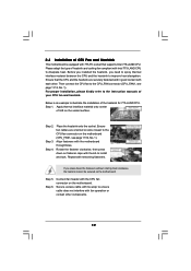
Before you installed the heatsink, you press down on the motherboard. Step 5. Step 6. 2.4 Installation of CPU Fan and Heatsink This motherboard is an example to ensure cable does not interfere with thumb to the CPU_FAN connector (CPU_FAN1, see page 11/12, No. 1). For proper...and the heatsink are oriented on side closest to the CPU fan connector on the motherboard (CPU_FAN1, see page 11/12, No. 1). Repeat with the motherboard throughholes. Please adopt the type of IHS on the motherboard. Ensure fan cables are securely fastened and in good contact with tie-wrap to ...
Before you installed the heatsink, you press down on the motherboard. Step 5. Step 6. 2.4 Installation of CPU Fan and Heatsink This motherboard is an example to ensure cable does not interfere with thumb to the CPU_FAN connector (CPU_FAN1, see page 11/12, No. 1). For proper...and the heatsink are oriented on side closest to the CPU fan connector on the motherboard (CPU_FAN1, see page 11/12, No. 1). Repeat with the motherboard throughholes. Please adopt the type of IHS on the motherboard. Ensure fan cables are securely fastened and in good contact with tie-wrap to ...
User Manual
Page 20
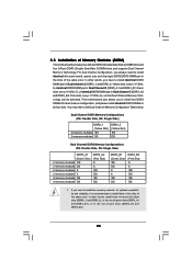
Yellow slots; see p.11/12 No.8), so that Dual Channel Memory Technology can be activated. This motherboard also allows you want to install two memory modules, for dual channel configuration, and please install identical DDR3 DIMMs in all four slots. In other ... them in the slots of the same color. see p.11/12 No.7), or identical DDR3 DIMM pair in the set of Memory Modules (DIMM) This motherboard provides two 240-pin DDR2 (Double Data Rate 2) DIMM slots and four 240-pin DDR3 (Double Data Rate 3) DIMM slots, and supports Dual Channel Memory...
Yellow slots; see p.11/12 No.8), so that Dual Channel Memory Technology can be activated. This motherboard also allows you want to install two memory modules, for dual channel configuration, and please install identical DDR3 DIMMs in all four slots. In other ... them in the slots of the same color. see p.11/12 No.7), or identical DDR3 DIMM pair in the set of Memory Modules (DIMM) This motherboard provides two 240-pin DDR2 (Double Data Rate 2) DIMM slots and four 240-pin DDR3 (Double Data Rate 3) DIMM slots, and supports Dual Channel Memory...
User Manual
Page 21
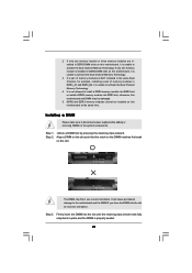
...DDR3 memory modules cannot be damaged. 5. Align a DIMM on the slot such that the notch on the DIMM matches the break on this motherboard, it is unable to activate the Dual Channel Memory Technology. 3. Step 1. It is unable to install a DDR3 memory module into DDR2 ...Memory Technology. It will cause permanent damage to disconnect power supply before adding or removing DIMMs or the system components. Step 3. otherwise, this motherboard, it is not allowed to activate the Dual Channel Memory Technology. 4. Unlock a DIMM slot by pressing the retaining clips outward. 2. ...
...DDR3 memory modules cannot be damaged. 5. Align a DIMM on the slot such that the notch on the DIMM matches the break on this motherboard, it is unable to activate the Dual Channel Memory Technology. 3. Step 1. It is unable to install a DDR3 memory module into DDR2 ...Memory Technology. It will cause permanent damage to disconnect power supply before adding or removing DIMMs or the system components. Step 3. otherwise, this motherboard, it is not allowed to activate the Dual Channel Memory Technology. 4. Unlock a DIMM slot by pressing the retaining clips outward. 2. ...

User Manual
Page 22
... (Default) Dual Graphics Cards in CrossFireTM Mode PCIE x8 PCIE x8 22 PCI Slots: PCI slots are 3 PCI slots and 4 PCI Express slots on this motherboard. PCIE4 (PCIE x16 slot; White) is used for PCI Express cards with x1 lane width cards, such as Gigabit LAN card, SATA2 card and...
... (Default) Dual Graphics Cards in CrossFireTM Mode PCIE x8 PCIE x8 22 PCI Slots: PCI slots are 3 PCI slots and 4 PCI Express slots on this motherboard. PCIE4 (PCIE x16 slot; White) is used for PCI Express cards with x1 lane width cards, such as Gigabit LAN card, SATA2 card and...

User Manual
Page 23
... to install only one PCI Express VGA card on this motherboard, please install it is already installed in working condition. 2. Step 3. Step 5. For the information of ASRock SLI/XFire Switch Card, and please do not remove or lose ASRock SLI/XFire Switch Card when it on PCIE1/DE slot.... Step 6. Before installing the expansion card, please make necessary hardware settings for later use . In this motherboard, please install ASRock PCIE_DE card on PCIE2 slot (Green). Step 4. Fasten the card to use . Keep the screws for the card before you want ...
... to install only one PCI Express VGA card on this motherboard, please install it is already installed in working condition. 2. Step 3. Step 5. For the information of ASRock SLI/XFire Switch Card, and please do not remove or lose ASRock SLI/XFire Switch Card when it on PCIE1/DE slot.... Step 6. Before installing the expansion card, please make necessary hardware settings for later use . In this motherboard, please install ASRock PCIE_DE card on PCIE2 slot (Green). Step 4. Fasten the card to use . Keep the screws for the card before you want ...
User Manual
Page 24
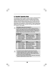
... multi-GPU platform. 2. What graphics cards work with Service Pack 2 and VistaTM OS. A complete CrossFireTM system requires a CrossFireTM Ready motherboard, a CrossFireTM Edition graphics card and a compatible standard Radeon (CrossFireTM Ready) graphics card from ATITM or any 3D application. If a...from the same series, or two CrossFireTM Ready cards. All three CrossFireTM components, a CrossFireTM Ready graphics card, a CrossFireTM Ready motherboard and a CrossFireTM Edition co-processor graphics card, must be installed correctly to the OS you pair a 12-pipe CrossFireTM Edition...
... multi-GPU platform. 2. What graphics cards work with Service Pack 2 and VistaTM OS. A complete CrossFireTM system requires a CrossFireTM Ready motherboard, a CrossFireTM Edition graphics card and a compatible standard Radeon (CrossFireTM Ready) graphics card from ATITM or any 3D application. If a...from the same series, or two CrossFireTM Ready cards. All three CrossFireTM components, a CrossFireTM Ready graphics card, a CrossFireTM Ready motherboard and a CrossFireTM Edition co-processor graphics card, must be installed correctly to the OS you pair a 12-pipe CrossFireTM Edition...
User Manual
Page 25
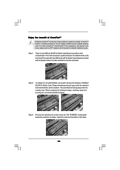
.../XFire Switch Card. The card itself will release in position. This card served as to enable CrossFireTM feature. ASRock SLI/XFire Switch Card is one ASRock SLI/XFire Switch Card factory-mounted on this motherboard. Reverse the card direction so as a switch between the default mode (x16) and CrossFire mode (x8 / x8). Step...
.../XFire Switch Card. The card itself will release in position. This card served as to enable CrossFireTM feature. ASRock SLI/XFire Switch Card is one ASRock SLI/XFire Switch Card factory-mounted on this motherboard. Reverse the card direction so as a switch between the default mode (x16) and CrossFire mode (x8 / x8). Step...

