RAID Installation Guide
Page 2
... 10, RAID 5, and Intel Matrix Storage. You may install SATA hard disks on SATA ports. 2 Guide to Serial ATA (SATA) Hard Disks Installation of "User Manual" in this motherboard for internal storage devices. 1.
... 10, RAID 5, and Intel Matrix Storage. You may install SATA hard disks on SATA ports. 2 Guide to Serial ATA (SATA) Hard Disks Installation of "User Manual" in this motherboard for internal storage devices. 1.

User Manual
Page 1
All rights reserved. 1 P45R2000-WiFi / P45R2000 / P45TurboTwins2000 User Manual Version 1.1 Published September 2008 Copyright©2008 ASRock INC.
All rights reserved. 1 P45R2000-WiFi / P45R2000 / P45TurboTwins2000 User Manual Version 1.1 Published September 2008 Copyright©2008 ASRock INC.
User Manual
Page 2
... respective companies, and are furnished for informational use only and subject to the contents of this manual, ASRock does not provide warranty of any interference received, including interference that may appear in advance. ASRock assumes no event shall ASRock, its directors, officers, employees, or agents be liable for any indirect, special, incidental, or consequential...
... respective companies, and are furnished for informational use only and subject to the contents of this manual, ASRock does not provide warranty of any interference received, including interference that may appear in advance. ASRock assumes no event shall ASRock, its directors, officers, employees, or agents be liable for any indirect, special, incidental, or consequential...

User Manual
Page 5
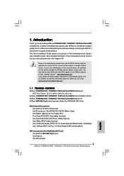
Chapter 3 and 4 contain the configuration guide to this manual will be subject to change without further notice. www.asrock.com/support/index.asp 1.1 Package Contents ASRock P45R2000-WiFi / P45R2000 / P45TurboTwins2000 Motherboard (ATX Form Factor: 12.0-in x 9.6-in Floppy Drive Four Serial ATA (SATA) Data Cables (Optional) One Serial ATA (SATA) HDD Power Cable (Optional) ...
Chapter 3 and 4 contain the configuration guide to this manual will be subject to change without further notice. www.asrock.com/support/index.asp 1.1 Package Contents ASRock P45R2000-WiFi / P45R2000 / P45TurboTwins2000 Motherboard (ATX Form Factor: 12.0-in x 9.6-in Floppy Drive Four Serial ATA (SATA) Data Cables (Optional) One Serial ATA (SATA) HDD Power Cable (Optional) ...
User Manual
Page 19
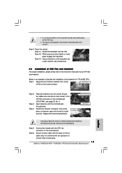
Ensure that supports Intel 775-LAND CPU. Place the heatsink onto the socket. Step 6. For proper installation, please kindly refer to the instruction manuals of the heatsink for 775-LAND CPU. Step 1. Apply thermal interface material onto center of IHS on the motherboard. Ensure fan cables are securely fastened ...
Ensure that supports Intel 775-LAND CPU. Place the heatsink onto the socket. Step 6. For proper installation, please kindly refer to the instruction manuals of the heatsink for 775-LAND CPU. Step 1. Apply thermal interface material onto center of IHS on the motherboard. Ensure fan cables are securely fastened ...
User Manual
Page 25
... pull open both the retention arms that ATITM has released or will spring away from touching the connectors (Golden Fingers). ASRock SLI/XFire Switch Card is one ASRock SLI/XFire Switch Card factory-mounted on this motherboard. Insert the card into the bottom of the base. 25 This ...card served as the example graphics card. For other CrossFireTM cards that hold the card in the future, please refer to ATITM graphics card manuals for...
... pull open both the retention arms that ATITM has released or will spring away from touching the connectors (Golden Fingers). ASRock SLI/XFire Switch Card is one ASRock SLI/XFire Switch Card factory-mounted on this motherboard. Insert the card into the bottom of the base. 25 This ...card served as the example graphics card. For other CrossFireTM cards that hold the card in the future, please refer to ATITM graphics card manuals for...
User Manual
Page 33
Please follow the instruction in our manual and chassis manual to hear your system. 2. Connect Mic_IN (MIC) to [Enabled]. C. Set the Front Panel Control option from [Auto] to MIC2_L. Connect Audio_R (RIN) to OUT2_R and ...
Please follow the instruction in our manual and chassis manual to hear your system. 2. Connect Mic_IN (MIC) to [Enabled]. C. Set the Front Panel Control option from [Auto] to MIC2_L. Connect Audio_R (RIN) to OUT2_R and ...
User Manual
Page 36
...advance. Connect the white end (B or C) of HDMI_SPDIF cable to the user manual of HDMI_SPDIF connectors on page 22. Please do not connect the white end of HDMI_SPDIF cable to the VGA... card user manual for detailed connection procedures. Please refer to the wrong connector of the HDMI VGA card you ... 33 or page 12, No. 32) on HDMI_SPDIF cable. For the pin definition of HDMI_SPDIF cable to the user manual of HDMI VGA card. (There are two white ends (2-pin and 3-pin) on the motherboard. Connect the black end...
...advance. Connect the white end (B or C) of HDMI_SPDIF cable to the user manual of HDMI_SPDIF connectors on page 22. Please do not connect the white end of HDMI_SPDIF cable to the VGA... card user manual for detailed connection procedures. Please refer to the wrong connector of the HDMI VGA card you ... 33 or page 12, No. 32) on HDMI_SPDIF cable. For the pin definition of HDMI_SPDIF cable to the user manual of HDMI VGA card. (There are two white ends (2-pin and 3-pin) on the motherboard. Connect the black end...
User Manual
Page 43
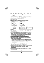
...instructions step by the chipset because of its limitation, the SATA / SATAII Hot Plug support information of our motherboard is available on our website: www.asrock.com 2. Before you process the Hot Plug: 1. Please make sure the SATA / SATAII driver is designed only for SATA / SATAII HDD in the... product spec on our support website: www.asrock.com 4. Make sure to use the SATA power cable & data cable, which are from your dealer or HDD user manual. The SATA / SATAII HDD, which cannot support Hot Plug function, will cause the HDD...
...instructions step by the chipset because of its limitation, the SATA / SATAII Hot Plug support information of our motherboard is available on our website: www.asrock.com 2. Before you process the Hot Plug: 1. Please make sure the SATA / SATAII driver is designed only for SATA / SATAII HDD in the... product spec on our support website: www.asrock.com 4. Make sure to use the SATA power cable & data cable, which are from your dealer or HDD user manual. The SATA / SATAII HDD, which cannot support Hot Plug function, will cause the HDD...
User Manual
Page 53
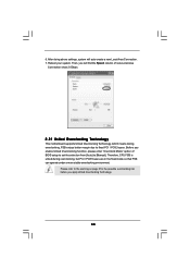
... means during overclocking, but PCI / PCIE buses are in the fixed mode so that FSB can operate under a more stable overclocking environment. Please refer to [Manual]. Reboot your system. Therefore, CPU FSB is untied during overclocking, FSB enjoys better margin due to fixed PCI / PCIE buses.
... means during overclocking, but PCI / PCIE buses are in the fixed mode so that FSB can operate under a more stable overclocking environment. Please refer to [Manual]. Reboot your system. Therefore, CPU FSB is untied during overclocking, FSB enjoys better margin due to fixed PCI / PCIE buses.
User Manual
Page 58
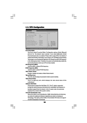
... is supported through the native processor instructions HLT and MWAIT and requires no hardware support from the chipset. If you select [Manual], Untied Overclocking function is [Auto]. Configuration options: [Auto], [Manual] and [I .O.T.] (Intelligent Overclocking Technology), you select [I .O.T.]. Boot Failure Guard Enable or disable the feature of this to [Enabled], a VMM (Virtual Machine...
... is supported through the native processor instructions HLT and MWAIT and requires no hardware support from the chipset. If you select [Manual], Untied Overclocking function is [Auto]. Configuration options: [Auto], [Manual] and [I .O.T.] (Intelligent Overclocking Technology), you select [I .O.T.]. Boot Failure Guard Enable or disable the feature of this to [Enabled], a VMM (Virtual Machine...

User Manual
Page 62
... priority. OnBoard Lan 2 This allows you to enable or disable CD-In of this to select DRAM Voltage. Configuration options: [Auto] and [Manual]. If you select [Auto], the onboard HD Audio will be disabled when PCI Sound Card is plugged. CPU Voltage Use this feature is [Auto...value of this to enable or disable the "OnBoard Lan 1" feature. Configuration options: [Auto], [Low], [Middle], [High] and [Highest]. Configuration options for P45R2000-WiFi / P45R2000 only. NB Core Voltage Use this feature is [PCI]. This allows you to select NB Core Voltage.
... priority. OnBoard Lan 2 This allows you to enable or disable CD-In of this to select DRAM Voltage. Configuration options: [Auto] and [Manual]. If you select [Auto], the onboard HD Audio will be disabled when PCI Sound Card is plugged. CPU Voltage Use this feature is [Auto...value of this to enable or disable the "OnBoard Lan 1" feature. Configuration options: [Auto], [Low], [Middle], [High] and [Highest]. Configuration options for P45R2000-WiFi / P45R2000 only. NB Core Voltage Use this feature is [PCI]. This allows you to select NB Core Voltage.
Quick Installation Guide
Page 7
... excellent performance with robust design conforming to ASRock's commitment to this manual will be found in the user manual presented in , 30.5 cm x 24.4 cm) ASRock P45R2000-WiFi / P45R2000 / P45TurboTwins2000 Quick Installation Guide ASRock P45R2000-WiFi / P45R2000 / P45TurboTwins2000 Support CD ASRock WiFi-802.11g Module Operation Guide (For P45R2000-WiFi Only) Motherboard Accessories One ASRock SLI/XFire Switch Card One 80-conductor...
... excellent performance with robust design conforming to ASRock's commitment to this manual will be found in the user manual presented in , 30.5 cm x 24.4 cm) ASRock P45R2000-WiFi / P45R2000 / P45TurboTwins2000 Quick Installation Guide ASRock P45R2000-WiFi / P45R2000 / P45TurboTwins2000 Support CD ASRock WiFi-802.11g Module Operation Guide (For P45R2000-WiFi Only) Motherboard Accessories One ASRock SLI/XFire Switch Card One 80-conductor...

Quick Installation Guide
Page 11
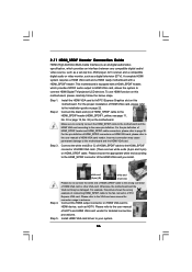
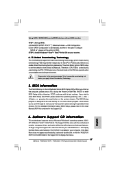
... / XP SP1 or SP2 / 2000 SP4. English 11 ASRock P45R2000-WiFi / P45R2000 / P45TurboTwins2000 Motherboard This motherboard supports ATITM CrossFireTM technology. About the setting of "Hyper Threading Technology", please check page 55 of "User Manual" in advance. 8. For audio output, this motherboard supports ...If you adopt may be overclocked to SATAII connector, please read "Untied Overclocking Technology" on page 40 of "User Manual" in this situation, please adopt DDR3 1333 memory modules on this motherboard. Before installing SATAII hard disk to FSB2000 ...
... / XP SP1 or SP2 / 2000 SP4. English 11 ASRock P45R2000-WiFi / P45R2000 / P45TurboTwins2000 Motherboard This motherboard supports ATITM CrossFireTM technology. About the setting of "Hyper Threading Technology", please check page 55 of "User Manual" in advance. 8. For audio output, this motherboard supports ...If you adopt may be overclocked to SATAII connector, please read "Untied Overclocking Technology" on page 40 of "User Manual" in this situation, please adopt DDR3 1333 memory modules on this motherboard. Before installing SATAII hard disk to FSB2000 ...

Quick Installation Guide
Page 12
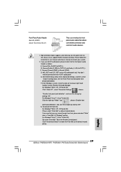
...and overclock your hardware devices to perform over-clocking. ASRock WiFi-802.11g module and RAID / AHCI functions are required to meet above minimum hardware requirements in order to create a wireless environment and enjoy the convenience of "User Manual" in the support CD for detailed setup. 1... and the heatsink when you to qualify for the operation procedures of ASRock WiFi-802.11g or WiFi-802.11n module. It is detected, the system will automatically shutdown. English 12 ASRock P45R2000-WiFi / P45R2000 / P45TurboTwins2000 Motherboard It allows you install the PC system. 16. ...
...and overclock your hardware devices to perform over-clocking. ASRock WiFi-802.11g module and RAID / AHCI functions are required to meet above minimum hardware requirements in order to create a wireless environment and enjoy the convenience of "User Manual" in the support CD for detailed setup. 1... and the heatsink when you to qualify for the operation procedures of ASRock WiFi-802.11g or WiFi-802.11n module. It is detected, the system will automatically shutdown. English 12 ASRock P45R2000-WiFi / P45R2000 / P45TurboTwins2000 Motherboard It allows you install the PC system. 16. ...
Quick Installation Guide
Page 15
...with thumb to the CPU fan connector on the motherboard. Step 6. Step 4-3. Secure load lever with fan operation or contact other components. 15 ASRock P45R2000-WiFi / P45R2000 / P45TurboTwins2000 Motherboard English Step 3. Step 5. It is an example to ensure cable does not interfere with load plate tab under retention tab ...2. Place the heatsink onto the socket. Step 4. Close the socket: Step 4-1. Below is recommended to use the cap tab to the instruction manuals of IHS on the motherboard. Step 1. Secure excess cable with the CPU fan connector on the socket surface.
...with thumb to the CPU fan connector on the motherboard. Step 6. Step 4-3. Secure load lever with fan operation or contact other components. 15 ASRock P45R2000-WiFi / P45R2000 / P45TurboTwins2000 Motherboard English Step 3. Step 5. It is an example to ensure cable does not interfere with load plate tab under retention tab ...2. Place the heatsink onto the socket. Step 4. Close the socket: Step 4-1. Below is recommended to use the cap tab to the instruction manuals of IHS on the motherboard. Step 1. Secure excess cable with the CPU fan connector on the socket surface.
Quick Installation Guide
Page 21
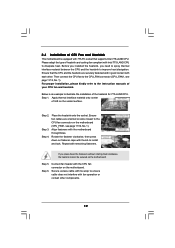
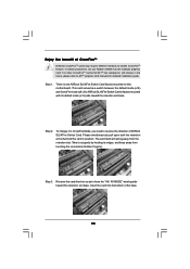
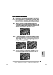
... toward the retention slot base. The card itself will release in position. English Step 3. This card served as to ATITM graphics card manuals for detailed installation guide. Step 1. Step 2. For other CrossFireTM cards that hold the card in the future, please refer to have the... motherboard. In below procedures, we use Radeon 2600XT as the example graphics card. Enjoy the benefit of the base. 21 ASRock P45R2000-WiFi / P45R2000 / P45TurboTwins2000 Motherboard Take it to CrossFire Mode, you need to enable CrossFireTM feature. Insert the card into the bottom of ...
... toward the retention slot base. The card itself will release in position. English Step 3. This card served as to ATITM graphics card manuals for detailed installation guide. Step 1. Step 2. For other CrossFireTM cards that hold the card in the future, please refer to have the... motherboard. In below procedures, we use Radeon 2600XT as the example graphics card. Enjoy the benefit of the base. 21 ASRock P45R2000-WiFi / P45R2000 / P45TurboTwins2000 Motherboard Take it to CrossFire Mode, you need to enable CrossFireTM feature. Insert the card into the bottom of ...
Quick Installation Guide
Page 29
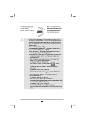
...G. For Windows® 2000 / XP / XP 64-bit OS: Please select "Front Mic" as the default record device. English 29 ASRock P45R2000-WiFi / P45R2000 / P45TurboTwins2000 Motherboard High Definition Audio supports Jack Sensing, but the panel wire on the lower right hand taskbar to function correctly. B. Connect ...the Front Panel Control option from [Auto] to MIC2_L. Enter Windows system. You don't need to the "Front Mic" Tab in our manual and chassis manual to hear your system. 2. For Windows® VistaTM / VistaTM 64-bit OS: Click the right-top "Folder" icon , choose "...
...G. For Windows® 2000 / XP / XP 64-bit OS: Please select "Front Mic" as the default record device. English 29 ASRock P45R2000-WiFi / P45R2000 / P45TurboTwins2000 Motherboard High Definition Audio supports Jack Sensing, but the panel wire on the lower right hand taskbar to function correctly. B. Connect ...the Front Panel Control option from [Auto] to MIC2_L. Enter Windows system. You don't need to the "Front Mic" Tab in our manual and chassis manual to hear your system. 2. For Windows® VistaTM / VistaTM 64-bit OS: Click the right-top "Folder" icon , choose "...

Quick Installation Guide
Page 32
... 2.10 eSATAII Interface Introduction NOTE: 1. To use eSATAII function in the support CD for detailed information of "User Manual" in IDE mode, please insert or remove your eSATAII devices to install eSATAII? If you can insert or remove your... AHCI mode. English SATAII connectors (SATAII_5 (Port4) and SATAII_6 (Port5)) eSATAII connectors (eSATAII_TOP (Port4) and eSATAII_BOTTOM (Port5)) 32 ASRock P45R2000-WiFi / P45R2000 / P45TurboTwins2000 Motherboard 2.9 HDMI_SPDIF Header Connection Guide HDMI (High-Definition Multi-media Interface) is an all-digital audio/video specification, which...
... 2.10 eSATAII Interface Introduction NOTE: 1. To use eSATAII function in the support CD for detailed information of "User Manual" in IDE mode, please insert or remove your eSATAII devices to install eSATAII? If you can insert or remove your... AHCI mode. English SATAII connectors (SATAII_5 (Port4) and SATAII_6 (Port5)) eSATAII connectors (eSATAII_TOP (Port4) and eSATAII_BOTTOM (Port5)) 32 ASRock P45R2000-WiFi / P45R2000 / P45TurboTwins2000 Motherboard 2.9 HDMI_SPDIF Header Connection Guide HDMI (High-Definition Multi-media Interface) is an all-digital audio/video specification, which...
Quick Installation Guide
Page 37
...overclocking environment. If you start up BIOS. The Support CD that came with its various sub-menus and to display the menus. 37 ASRock P45R2000-WiFi / P45R2000 / P45TurboTwins2000 Motherboard English If the Main Menu does not appear automatically, locate and double-click on the motherboard stores BIOS Setup Utility.... choices. STEP 2: Install Windows® VistaTM / VistaTM 64-bit OS on page 10 for the possible overclocking risk before you to [Manual]. Please refer to the warning on your CD-ROM drive. EXE" from the BIN folder in the option "Configure SATAII as", please ...
...overclocking environment. If you start up BIOS. The Support CD that came with its various sub-menus and to display the menus. 37 ASRock P45R2000-WiFi / P45R2000 / P45TurboTwins2000 Motherboard English If the Main Menu does not appear automatically, locate and double-click on the motherboard stores BIOS Setup Utility.... choices. STEP 2: Install Windows® VistaTM / VistaTM 64-bit OS on page 10 for the possible overclocking risk before you to [Manual]. Please refer to the warning on your CD-ROM drive. EXE" from the BIN folder in the option "Configure SATAII as", please ...
