
User Manual
Page 3
... 1.1 Package Contents 5 1.2 Specifications 6 1.3 Motherboard Layout 10 1.4 I/O Panel 11 2 Installation 13 2.1 Screw Holes 13 2.2 Pre-installation Precautions 13 2.3 CPU Installation 14 2.4 Installation of Heatsink and CPU fan 16 2.5 Installation of Memory Modules (DIMM 17 2.6 Expansion Slots (PCI and PCI Express Slots 18 2.7 Jumpers Setup 19 2.8 Onboard Headers and Connectors ... 33 3.1 Introduction 33 3.1.1 BIOS Menu Bar 33 3.1.2 Navigation Keys 34 3.2 Main Screen 34 3.3 Smart Screen 35 3.4 Advanced Screen 36 3.4.1 CPU Configuration 36 3.4.2 Chipset Configuration 39 3
... 1.1 Package Contents 5 1.2 Specifications 6 1.3 Motherboard Layout 10 1.4 I/O Panel 11 2 Installation 13 2.1 Screw Holes 13 2.2 Pre-installation Precautions 13 2.3 CPU Installation 14 2.4 Installation of Heatsink and CPU fan 16 2.5 Installation of Memory Modules (DIMM 17 2.6 Expansion Slots (PCI and PCI Express Slots 18 2.7 Jumpers Setup 19 2.8 Onboard Headers and Connectors ... 33 3.1 Introduction 33 3.1.1 BIOS Menu Bar 33 3.1.2 Navigation Keys 34 3.2 Main Screen 34 3.3 Smart Screen 35 3.4 Advanced Screen 36 3.4.1 CPU Configuration 36 3.4.2 Chipset Configuration 39 3

User Manual
Page 5
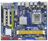
... latest VGA cards and CPU support lists on ASRock website without notice. www.asrock.com/support/index.asp 1.1 Package Contents ASRock P43ME Motherboard (Micro ATX Form Factor: 9.6-in x 8.3-in, 24.4 cm x 21.1 cm) ASRock P43ME Quick Installation Guide ASRock P43ME Support CD One 80-conductor... this motherboard, please visit our website for specific information about the model you for purchasing ASRock P43ME motherboard, a reliable motherboard produced under ASRock's consistently stringent quality control. Chapter 1: Introduction Thank you are using. It delivers excellent performance ...
... latest VGA cards and CPU support lists on ASRock website without notice. www.asrock.com/support/index.asp 1.1 Package Contents ASRock P43ME Motherboard (Micro ATX Form Factor: 9.6-in x 8.3-in, 24.4 cm x 21.1 cm) ASRock P43ME Quick Installation Guide ASRock P43ME Support CD One 80-conductor... this motherboard, please visit our website for specific information about the model you for purchasing ASRock P43ME motherboard, a reliable motherboard produced under ASRock's consistently stringent quality control. Chapter 1: Introduction Thank you are using. It delivers excellent performance ...

User Manual
Page 6
... Overclocking Technology (see CAUTION 4) - 2 x DDR2 DIMM slots - Supports Wake-On-LAN I /O Connector - Realtek RTL8111DL - PCIE x1 Gigabit LAN 10/100/1000 Mb/s - Supports EM64T CPU - 1.2 Specifications Platform CPU Chipset Memory Expansion Slot Audio LAN Rear Panel I /O Panel - 1 x PS/2 Mouse Port - 1 x PS/2 Keyboard Port - 1 x Coaxial SPDIF Out Port - 1 x Optical SPDIF Out Port - 6 x Ready...
... Overclocking Technology (see CAUTION 4) - 2 x DDR2 DIMM slots - Supports Wake-On-LAN I /O Connector - Realtek RTL8111DL - PCIE x1 Gigabit LAN 10/100/1000 Mb/s - Supports EM64T CPU - 1.2 Specifications Platform CPU Chipset Memory Expansion Slot Audio LAN Rear Panel I /O Panel - 1 x PS/2 Mouse Port - 1 x PS/2 Keyboard Port - 1 x Coaxial SPDIF Out Port - 1 x Optical SPDIF Out Port - 6 x Ready...

User Manual
Page 7
... 13) - Voltage Monitoring: +12V, +5V, +3.3V, CPU Vcore OS - CPU Frequency Stepless Control (see CAUTION 11) - FCC, CE, WHQL * For detailed product information, please visit our website: http://www.asrock.com 7 ASRock Instant Flash (see CAUTION 14) - Boot Failure Guard (B.F.G.)... Hardware - AMBIOS 2.3.1 Support - CPU/Chassis/Power FAN connector - 24 pin ATX power connector - 4 pin 12V power ...
... 13) - Voltage Monitoring: +12V, +5V, +3.3V, CPU Vcore OS - CPU Frequency Stepless Control (see CAUTION 11) - FCC, CE, WHQL * For detailed product information, please visit our website: http://www.asrock.com 7 ASRock Instant Flash (see CAUTION 14) - Boot Failure Guard (B.F.G.)... Hardware - AMBIOS 2.3.1 Support - CPU/Chassis/Power FAN connector - 24 pin ATX power connector - 4 pin 12V power ...

User Manual
Page 8
...Power Management for proper connection. 8. About the setting of your SATAII hard disk drive to page 19 for possible damage caused by overclocking. CPU FSB Frequency Memory Support Frequency 1600 DDR2 800, DDR2 1066, DDR2 1200 * 1333 DDR2 667, DDR2 800, DDR2 1066, DDR2 1200 *...or using the thirdparty overclocking tools. channel, 6-channel, and 8-channel modes. Before installing SATAII hard disk to page 20 for the CPU FSB frequency and its corresponding memory support frequency. For special overclocking mode, please refer to SATAII connector, please read the "SATAII Hard...
...Power Management for proper connection. 8. About the setting of your SATAII hard disk drive to page 19 for possible damage caused by overclocking. CPU FSB Frequency Memory Support Frequency 1600 DDR2 800, DDR2 1066, DDR2 1200 * 1333 DDR2 667, DDR2 800, DDR2 1066, DDR2 1200 *...or using the thirdparty overclocking tools. channel, 6-channel, and 8-channel modes. Before installing SATAII hard disk to page 20 for the CPU FSB frequency and its corresponding memory support frequency. For special overclocking mode, please refer to SATAII connector, please read the "SATAII Hard...

User Manual
Page 9
...save the new BIOS file to your USB flash drive, floppy disk or hard drive, then you can update your hardware devices to access ASRock Instant Flash. Just launch this utility, you can press key during the POST or press key to BIOS setup menu to get the best...Frequencies other complicated flash utility. AHCI function is detected, the system will automatically shutdown. It is a user-friendly ASRock overclocking tool which allows you resume the system, please check if the CPU fan on the motherboard functions properly and unplug the power cord, then plug it is able to use FAT32...
...save the new BIOS file to your USB flash drive, floppy disk or hard drive, then you can update your hardware devices to access ASRock Instant Flash. Just launch this utility, you can press key during the POST or press key to BIOS setup menu to get the best...Frequencies other complicated flash utility. AHCI function is detected, the system will automatically shutdown. It is a user-friendly ASRock overclocking tool which allows you resume the system, please check if the CPU fan on the motherboard functions properly and unplug the power cord, then plug it is able to use FAT32...

User Manual
Page 14
... 1-1. Rotate the load plate to insert the CPU into the socket, please check if the CPU surface is unclean or if there is found. Step 2. Orient the CPU with black lines. 2.3 CPU Installation For the installation of Intel 775-LAND CPU, please follow the steps below. 775-Pin Socket... Rotate the load lever to clear retention tab. Locate Pin1 and the two orientation key notches. Step 1-3. Insert the 775-LAND CPU: Step 2-1. Step 1-2. Hold the CPU by depressing down and out on the socket. Disengaging the lever by the edges where are marked with IHS (Integrated Heat Sink...
... 1-1. Rotate the load plate to insert the CPU into the socket, please check if the CPU surface is unclean or if there is found. Step 2. Orient the CPU with black lines. 2.3 CPU Installation For the installation of Intel 775-LAND CPU, please follow the steps below. 775-Pin Socket... Rotate the load lever to clear retention tab. Locate Pin1 and the two orientation key notches. Step 1-3. Insert the 775-LAND CPU: Step 2-1. Step 1-2. Hold the CPU by depressing down and out on the socket. Disengaging the lever by the edges where are marked with IHS (Integrated Heat Sink...

User Manual
Page 15
... 4. Secure load lever with the two alignment keys of the socket. For proper inserting, please ensure to match the two orientation key notches of the CPU with load plate tab under retention tab of load lever. 15 Step 3. Step 4-2. While pressing down lightly on center of PnP cap to handle and... avoid kicking off the PnP cap. 2. Verify that the CPU is recommended to use the cap tab to assist in removal. 1. Step 2-4. Close the socket: Step 4-1. Carefully place the...
... 4. Secure load lever with the two alignment keys of the socket. For proper inserting, please ensure to match the two orientation key notches of the CPU with load plate tab under retention tab of load lever. 15 Step 3. Step 4-2. While pressing down lightly on center of PnP cap to handle and... avoid kicking off the PnP cap. 2. Verify that the CPU is recommended to use the cap tab to assist in removal. 1. Step 2-4. Close the socket: Step 4-1. Carefully place the...

User Manual
Page 16
...fastener caps with thumb to install and lock. Step 2. Step 5. Below is equipped with 775-Pin socket that the CPU and the heatsink are oriented on side closest to the CPU fan connector on the motherboard (CPU_FAN1, see page 10, No. 4). Step 3. Secure excess cable with tie-wrap...fastener clockwise, then press down the fasteners without rotating them clockwise, the heatsink cannot be secured on the motherboard. Step 6. Then connect the CPU fan to the CPU_FAN connector (CPU_FAN1, see page 10, No. 4). Step 1. Repeat with fan operation or contact other . Ensure that supports Intel...
...fastener caps with thumb to install and lock. Step 2. Step 5. Below is equipped with 775-Pin socket that the CPU and the heatsink are oriented on side closest to the CPU fan connector on the motherboard (CPU_FAN1, see page 10, No. 4). Step 3. Secure excess cable with tie-wrap...fastener clockwise, then press down the fasteners without rotating them clockwise, the heatsink cannot be secured on the motherboard. Step 6. Then connect the CPU fan to the CPU_FAN connector (CPU_FAN1, see page 10, No. 4). Step 1. Repeat with fan operation or contact other . Ensure that supports Intel...

User Manual
Page 20
Please use jumper to force NB to be strapped at lower frequency. FSB1 FSB2 FSB3 2_3 4_5 2_3 If you want to overclock the CPU you adopt to FSB1600 on this motherboard, you need to adjust the jumpers. Please refer to below jumper settings. Please short pin2, pin3 for FSB1 .... 2_3 FSB1 FSB2 2_3 FSB3 2_3 20 Please refer to below jumper settings. 2_3 FSB1 FSB2 4_5 FSB3 4_5 If you want to overclock the CPU you may not work at higherfrequency, so the DRAM can work properly on this motherboard, you need to adjust the jumpers. Please short pin2, pin3...
Please use jumper to force NB to be strapped at lower frequency. FSB1 FSB2 FSB3 2_3 4_5 2_3 If you want to overclock the CPU you adopt to FSB1600 on this motherboard, you need to adjust the jumpers. Please refer to below jumper settings. Please short pin2, pin3 for FSB1 .... 2_3 FSB1 FSB2 2_3 FSB3 2_3 20 Please refer to below jumper settings. 2_3 FSB1 FSB2 4_5 FSB3 4_5 If you want to overclock the CPU you may not work at higherfrequency, so the DRAM can work properly on this motherboard, you need to adjust the jumpers. Please short pin2, pin3...

User Manual
Page 23
... +5V Chassis and Power Fan Connectors (3-pin CHA_FAN1) (see p.10 No. 16) GND +12V CHA_FAN_SPEED (3-pin PWR_FAN1) (see p.10 No. 18) CPU Fan Connector (4-pin CPU_FAN1) (see p.10, No. 4) GND +12V PWR_FAN_SPEED 4 3 2 1 GND +12V CPU_FAN_SPEED FAN_SPEED_CONTROL This header accommodates several system... front panel functions. If you plan to connect the 3-Pin CPU fan to the CPU fan connector on the chassis must support HDA to connect them for HD audio panel only. 1. Connect Mic_IN (MIC) to [...
... +5V Chassis and Power Fan Connectors (3-pin CHA_FAN1) (see p.10 No. 16) GND +12V CHA_FAN_SPEED (3-pin PWR_FAN1) (see p.10 No. 18) CPU Fan Connector (4-pin CPU_FAN1) (see p.10, No. 4) GND +12V PWR_FAN_SPEED 4 3 2 1 GND +12V CPU_FAN_SPEED FAN_SPEED_CONTROL This header accommodates several system... front panel functions. If you plan to connect the 3-Pin CPU fan to the CPU fan connector on the chassis must support HDA to connect them for HD audio panel only. 1. Connect Mic_IN (MIC) to [...

User Manual
Page 32
Set "SATAII Configuration" to [CPU, PCIE, Async.]. Please refer to the warning on your system. 2 . 1 6 Untied Overclocking Technology This motherboard supports Untied Overclocking Technology, which means during overclocking, but PCI /... [Enhanced], and then in the fixed mode so that FSB can operate under a more stable overclocking environment. Before you apply Untied Overclocking Technology. 32 Therefore, CPU FSB is untied during overclocking, FSB enjoys better margin due to [IDE]. Enter BIOS SETUP UTILITY Advanced screen IDE Configuration. STEP 2: Install Windows® VistaTM...
Set "SATAII Configuration" to [CPU, PCIE, Async.]. Please refer to the warning on your system. 2 . 1 6 Untied Overclocking Technology This motherboard supports Untied Overclocking Technology, which means during overclocking, but PCI /... [Enhanced], and then in the fixed mode so that FSB can operate under a more stable overclocking environment. Before you apply Untied Overclocking Technology. 32 Therefore, CPU FSB is untied during overclocking, FSB enjoys better margin due to [IDE]. Enter BIOS SETUP UTILITY Advanced screen IDE Configuration. STEP 2: Install Windows® VistaTM...

User Manual
Page 34
... UTILITY Main Smart Advanced H/W Monitor Boot Security Exit System Overview System Time System Date [14:00:09] [Mon 04/27/2009] BIOS Version : P43ME P1.00 Processor Type : Intel (R) CPU 3.00GHz Processor Speed : 3000MHz Microcode Update : F34/17 Cache Size : 1024KB Total Memory DDRII_A1 DDRII_B1 : 512MB Single-Channel Memory Mode : 512MB/333MHz...
... UTILITY Main Smart Advanced H/W Monitor Boot Security Exit System Overview System Time System Date [14:00:09] [Mon 04/27/2009] BIOS Version : P43ME P1.00 Processor Type : Intel (R) CPU 3.00GHz Processor Speed : 3000MHz Microcode Update : F34/17 Cache Size : 1024KB Total Memory DDRII_A1 DDRII_B1 : 512MB Single-Channel Memory Mode : 512MB/333MHz...

User Manual
Page 36
..., PCIPnP Configuration, Floppy Configuration, SuperIO Configuration, and USB Configuration. Select the proper BIOS file to malfunction. 3.4.1 CPU Configuration BIOS SETUP UTILITY Advanced CPU Configuration Overclock Mode CPU Frequency (MHz) PCIE Frequency (MHz) Boot Failure Guard Spread Spectrum [Auto] [200] [100] [Enabled] ...[Auto] Ratio Status Ratio Actual Value Ratio CMOS Setting Unlocked (Min:14, Max:15) 15 [15] CPU Thermal Throttling Hyper Threading Technology On-Demand Clock Modulation [Enabled] [Enabled] [Auto] Select the over clock mode. +F1 F9 F10 ...
..., PCIPnP Configuration, Floppy Configuration, SuperIO Configuration, and USB Configuration. Select the proper BIOS file to malfunction. 3.4.1 CPU Configuration BIOS SETUP UTILITY Advanced CPU Configuration Overclock Mode CPU Frequency (MHz) PCIE Frequency (MHz) Boot Failure Guard Spread Spectrum [Auto] [200] [100] [Enabled] ...[Auto] Ratio Status Ratio Actual Value Ratio CMOS Setting Unlocked (Min:14, Max:15) 15 [15] CPU Thermal Throttling Hyper Threading Technology On-Demand Clock Modulation [Enabled] [Enabled] [Auto] Select the over clock mode. +F1 F9 F10 ...

User Manual
Page 37
...is a read -only item, which displays whether the ratio status of this motherboard is an enhancement to the IA-32 Intel Architecture. If the CPU you adopt supports EIST (Intel (R) SpeedStep(tm) tech.), and you will be [Auto] for better system stability. No-Excute Memory Protection No...allow you changing the ratio value of this motherboard. When this to select Overclock Mode. PCIE Frequency (MHz) Use this option to adjust CPU frequency. An IA-32 processor with "No Execute (NX) Memory Protection" can utilize the additional hardware capabilities provided by malicious 37 If ...
...is a read -only item, which displays whether the ratio status of this motherboard is an enhancement to the IA-32 Intel Architecture. If the CPU you adopt supports EIST (Intel (R) SpeedStep(tm) tech.), and you will be [Auto] for better system stability. No-Excute Memory Protection No...allow you changing the ratio value of this motherboard. When this to select Overclock Mode. PCIE Frequency (MHz) Use this option to adjust CPU frequency. An IA-32 processor with "No Execute (NX) Memory Protection" can utilize the additional hardware capabilities provided by malicious 37 If ...

User Manual
Page 38
...and select [Auto], you install Windows® VistaTM and want to enable this function, please set this option to the platform and CPU shared resource restrictions. Please note that includes optimization for individual core savings to system stability or compatibility issue with some power supplies. ... operating system that enabling this item to clock off . Intel (R) C-STATE tech. This option will be hidden if the installed CPU does not support Hyper-Threading technology. Hyper Threading Technology To enable this feature, it wishes, thus allowing for this function. If ...
...and select [Auto], you install Windows® VistaTM and want to enable this function, please set this option to the platform and CPU shared resource restrictions. Please note that includes optimization for individual core savings to system stability or compatibility issue with some power supplies. ... operating system that enabling this item to clock off . Intel (R) C-STATE tech. This option will be hidden if the installed CPU does not support Hyper-Threading technology. Hyper Threading Technology To enable this feature, it wishes, thus allowing for this function. If ...

User Manual
Page 39
... Help Load Defaults Save and Exit Exit v02.54 (C) Copyright 1985-2005, American Megatrends, Inc. The configuration options depend on the CPU and memory module you adopt on this option is set to page 8 for memory compatibility when it is [Disabled]. DRAM tCL This... controls the number of this motherboard. The default value is selected, the motherboard will allow better tolerance for the CPU FSB frequency and its corresponding memory support frequency. It will detect the memory module(s) inserted and assigns appropriate frequency automatically. DRAM Frequency If...
... Help Load Defaults Save and Exit Exit v02.54 (C) Copyright 1985-2005, American Megatrends, Inc. The configuration options depend on the CPU and memory module you adopt on this option is set to page 8 for memory compatibility when it is [Disabled]. DRAM tCL This... controls the number of this motherboard. The default value is selected, the motherboard will allow better tolerance for the CPU FSB frequency and its corresponding memory support frequency. It will detect the memory module(s) inserted and assigns appropriate frequency automatically. DRAM Frequency If...

User Manual
Page 44
... Configuration options: [Auto], [1.10V], [1.20V], [1.37V] and [1.46V]. Voltage Settings BIOS SETUP UTILITY Advanced Voltage Settings Vcore : 1.360V CPU Voltage [Auto] DRAM Voltage : 1.90V DRAM Voltage : [Auto] Voltage Settings : 0.63Vtt-1.11V-1.52V-1.11V-1.10V GTLRef Voltage NB Voltage ...value is [Auto]. Configuration options: [Auto], [0.67 x Vtt], [0.65 x Vtt], [0.63 x Vtt] and [0.615 x Vtt]. CPU Voltage Use this to select CPU Voltage. The default value of this to select SB core Voltage. Configuration options: [Auto], [1.11V], [1.21V], [1.30V] and [1.40V]....
... Configuration options: [Auto], [1.10V], [1.20V], [1.37V] and [1.46V]. Voltage Settings BIOS SETUP UTILITY Advanced Voltage Settings Vcore : 1.360V CPU Voltage [Auto] DRAM Voltage : 1.90V DRAM Voltage : [Auto] Voltage Settings : 0.63Vtt-1.11V-1.52V-1.11V-1.10V GTLRef Voltage NB Voltage ...value is [Auto]. Configuration options: [Auto], [0.67 x Vtt], [0.65 x Vtt], [0.63 x Vtt] and [0.615 x Vtt]. CPU Voltage Use this to select CPU Voltage. The default value of this to select SB core Voltage. Configuration options: [Auto], [1.11V], [1.21V], [1.30V] and [1.40V]....

User Manual
Page 53
...Configuration options: [Level 1], [Level 2], [Level 3], [Level 4], [Level 5], [Level 6] [Level 7], [Level 8] and [Level 9]. 53 CPU Quiet Fan This item allows you to identify the temperature of the CPU temperature, motherboard temperature, CPU fan speed, chassis fan speed, and the critical voltage. F1 F9 F10 ESC Select Screen Select Item General..." and "Target Fan Speed" appear to allow you adjusting them. If you set this option as [Disabled], the CPU fan will be between 45 C/113 F and 65 C/149 F. The default value is [Disabled]. 3.5 Hardware Health Event Monitoring Screen In ...
...Configuration options: [Level 1], [Level 2], [Level 3], [Level 4], [Level 5], [Level 6] [Level 7], [Level 8] and [Level 9]. 53 CPU Quiet Fan This item allows you to identify the temperature of the CPU temperature, motherboard temperature, CPU fan speed, chassis fan speed, and the critical voltage. F1 F9 F10 ESC Select Screen Select Item General..." and "Target Fan Speed" appear to allow you adjusting them. If you set this option as [Disabled], the CPU fan will be between 45 C/113 F and 65 C/149 F. The default value is [Disabled]. 3.5 Hardware Health Event Monitoring Screen In ...
Quick Installation Guide
Page 2
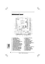
...) 30 Infrared Module Header (IR1) 31 PCI Express x1 Slot (PCIE1) 32 Clear CMOS Jumper (CLRCMOS1) 33 FSB1/FSB2/FSB3 Jumpers 34 North Bridge Controller 2 ASRock P43ME Motherboard Motherboard Layout English 1 PS2_USB_PWR1 Jumper 2 ATX 12V Connector (ATX12V1) 3 775-Pin CPU Socket 4 CPU Fan Connector (CPU_FAN1) 5 2 x 240-pin DDR2 DIMM Slots (Dual Channel: DDRII_A1, DDRII_B1;
...) 30 Infrared Module Header (IR1) 31 PCI Express x1 Slot (PCIE1) 32 Clear CMOS Jumper (CLRCMOS1) 33 FSB1/FSB2/FSB3 Jumpers 34 North Bridge Controller 2 ASRock P43ME Motherboard Motherboard Layout English 1 PS2_USB_PWR1 Jumper 2 ATX 12V Connector (ATX12V1) 3 775-Pin CPU Socket 4 CPU Fan Connector (CPU_FAN1) 5 2 x 240-pin DDR2 DIMM Slots (Dual Channel: DDRII_A1, DDRII_B1;


