
User Manual
Page 2
...cause undesired operation. "Perchlorate Material-special handling may apply, see www.dtsc.ca.gov/hazardouswaste/perchlorate" ASRock Website: http://www.asrock.com 2 ASRock assumes no event shall ASRock, its directors, officers, employees, or agents be liable for any indirect, special, incidental, or ..., without notice, and should not be constructed as a commitment by ASRock. This device complies with Part 15 of the FCC Rules. CALIFORNIA, USA ONLY The Lithium battery adopted on this motherboard contains Perchlorate, a toxic substance controlled in Perchlorate Best Management Practices ...
...cause undesired operation. "Perchlorate Material-special handling may apply, see www.dtsc.ca.gov/hazardouswaste/perchlorate" ASRock Website: http://www.asrock.com 2 ASRock assumes no event shall ASRock, its directors, officers, employees, or agents be liable for any indirect, special, incidental, or ..., without notice, and should not be constructed as a commitment by ASRock. This device complies with Part 15 of the FCC Rules. CALIFORNIA, USA ONLY The Lithium battery adopted on this motherboard contains Perchlorate, a toxic substance controlled in Perchlorate Best Management Practices ...

User Manual
Page 3
Introduction 5 1.1 Package Contents 5 1.2 Specifications 6 1.3 Motherboard Layout 10 1.4 ASRock HD 6CH I/O 11 2 . Installation 12 Pre-installation Precautions 12 2.1 CPU Installation 13 2.2 Installation of CPU Fan and Heatsink 13 2.3 Installation of Memory Modules (DIMM 14 2.4 ...
Introduction 5 1.1 Package Contents 5 1.2 Specifications 6 1.3 Motherboard Layout 10 1.4 ASRock HD 6CH I/O 11 2 . Installation 12 Pre-installation Precautions 12 2.1 CPU Installation 13 2.2 Installation of CPU Fan and Heatsink 13 2.3 Installation of Memory Modules (DIMM 14 2.4 ...
User Manual
Page 5
...be subject to the hardware installation. www.asrock.com/support/index.asp 1.1 Package Contents 1 x ASRock NF6-GLAN Motherboard (ATX Form Factor: 12.0-in x 8.0-in, 30.5 cm x 20.3 cm) 1 x ASRock NF6-GLAN Quick Installation Guide 1 x ASRock NF6-GLAN Support CD 1 x Ultra ATA 66/100...) 1 x Serial ATA (SATA) HDD Power Cable (Optional) 1 x "ASRock HD 6CH I/O" I/O Shield 5 In this motherboard, please visit our website for purchasing ASRock NF6-GLAN motherboard, a reliable motherboard produced under ASRock's consistently stringent quality control. In case any modifications of this manual occur, the...
...be subject to the hardware installation. www.asrock.com/support/index.asp 1.1 Package Contents 1 x ASRock NF6-GLAN Motherboard (ATX Form Factor: 12.0-in x 8.0-in, 30.5 cm x 20.3 cm) 1 x ASRock NF6-GLAN Quick Installation Guide 1 x ASRock NF6-GLAN Support CD 1 x Ultra ATA 66/100...) 1 x Serial ATA (SATA) HDD Power Cable (Optional) 1 x "ASRock HD 6CH I/O" I/O Shield 5 In this motherboard, please visit our website for purchasing ASRock NF6-GLAN motherboard, a reliable motherboard produced under ASRock's consistently stringent quality control. In case any modifications of this manual occur, the...
User Manual
Page 8
... bus frequencies may be less than 4GB for the reservation for the operation procedures of ASRock WiFi-802.11g or WiFi-802.11n module. This motherboard supports Dual Channel Memory Technology. Due to SATAII connector directly. 6. This motherboard supports Untied Overclocking Technology. Whether 1066MHz memory speed is supported depends on the AM2+ CPU...
... bus frequencies may be less than 4GB for the reservation for the operation procedures of ASRock WiFi-802.11g or WiFi-802.11n module. This motherboard supports Dual Channel Memory Technology. Due to SATAII connector directly. 6. This motherboard supports Untied Overclocking Technology. Whether 1066MHz memory speed is supported depends on the AM2+ CPU...
User Manual
Page 9
10. This motherboard supports ASRock AM2 Boost overclocking technology. Before you enable this function in the BIOS setup, the memory performance will improve up to disable this function will automatically ... spray thermal grease between the CPU and the heatsink when you adopt. If you resume the system, please check if the CPU fan on the motherboard functions properly and unplug the power cord, then plug it may choose to 12.5%, but the effect still depends on the AM2 CPU you install...
10. This motherboard supports ASRock AM2 Boost overclocking technology. Before you enable this function in the BIOS setup, the memory performance will improve up to disable this function will automatically ... spray thermal grease between the CPU and the heatsink when you adopt. If you resume the system, please check if the CPU fan on the motherboard functions properly and unplug the power cord, then plug it may choose to 12.5%, but the effect still depends on the AM2 CPU you install...
User Manual
Page 10
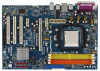
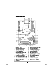
...Floppy Connector (FLOPPY1) 7 2 x 240-pin DDR2 DIMM Slots 23 Internal Audio Connector: CD1 (Black) (Dual Channel B: DDRII_3, DDRII_4; 1.3 Motherboard Layout 1 23 45 20.3cm (8.0-in) PS2 Mouse PS2_USB_PW1 ATX12V1 CPU_FAN1 67 PARALLEL PORT PS2 Keyboard COM1 DDR2 800 DDRII_1 (64 bit, 240-piFnSmBod8ul0e...USB4 B: USB5 30 LAN 29 PHY ATXPWR1 Top: LINE IN Center: FRONT Bottom: MIC IN PCIE1 Dual Channel PCIE2 AM2+ AM2 PCI EXPRESS NF6-GLAN IDE1 CLRCMOS1 1 28 27 26 25 PCIE3/DE Super I/O PCI1 1 HDMI_SPDIF1 AUDIO CODEC HD_AUDIO1 1 1 WIFI PCI2 PCI3 CD1 FLOPPY1 RoHS SATAII...
...Floppy Connector (FLOPPY1) 7 2 x 240-pin DDR2 DIMM Slots 23 Internal Audio Connector: CD1 (Black) (Dual Channel B: DDRII_3, DDRII_4; 1.3 Motherboard Layout 1 23 45 20.3cm (8.0-in) PS2 Mouse PS2_USB_PW1 ATX12V1 CPU_FAN1 67 PARALLEL PORT PS2 Keyboard COM1 DDR2 800 DDRII_1 (64 bit, 240-piFnSmBod8ul0e...USB4 B: USB5 30 LAN 29 PHY ATXPWR1 Top: LINE IN Center: FRONT Bottom: MIC IN PCIE1 Dual Channel PCIE2 AM2+ AM2 PCI EXPRESS NF6-GLAN IDE1 CLRCMOS1 1 28 27 26 25 PCIE3/DE Super I/O PCI1 1 HDMI_SPDIF1 AUDIO CODEC HD_AUDIO1 1 1 WIFI PCI2 PCI3 CD1 FLOPPY1 RoHS SATAII...

User Manual
Page 12
...is an ATX form factor (12.0-in x 8.0-in the bag that the motherboard fits into the screw holes to secure the motherboard to ensure that comes with the component. 5. Failure to do so may damage the motherboard. 12 Hold components by the edges and do not over-tighten the screws!... the power cord from the power supply. Also remember to use a grounded wrist strap or touch a safety grounded object before you uninstall any motherboard settings. When placing screws into it on the carpet or the like. Doing so may cause severe damage to static electricity, NEVER place your ...
...is an ATX form factor (12.0-in x 8.0-in the bag that the motherboard fits into the screw holes to secure the motherboard to ensure that comes with the component. 5. Failure to do so may damage the motherboard. 12 Hold components by the edges and do not over-tighten the screws!... the power cord from the power supply. Also remember to use a grounded wrist strap or touch a safety grounded object before you uninstall any motherboard settings. When placing screws into it on the carpet or the like. Doing so may cause severe damage to static electricity, NEVER place your ...
User Manual
Page 13
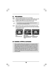
... to secure the CPU. Step 2. Step 3. The CPU fits only in place. The lever clicks on the socket while you install the CPU into this motherboard, it fits in one correct orientation. Then connect the CPU fan to indicate that the CPU corner with the golden triangle matches the socket corner...
... to secure the CPU. Step 2. Step 3. The CPU fits only in place. The lever clicks on the socket while you install the CPU into this motherboard, it fits in one correct orientation. Then connect the CPU fan to indicate that the CPU corner with the golden triangle matches the socket corner...

User Manual
Page 14
... Populated (3)* Populated Populated Populated Populated * For the configuration (3), please install identical DDR2 DIMMs in the set of Memory Modules (DIMM) This motherboard provides four 240-pin DDR2 (Double Data Rate 2) DIMM slots, and supports Dual Channel Memory Technology. If a pair of memory modules is...Channel A (DDRII_1 and DDRII_2; You may be activated. If you to the Dual Channel Memory Configuration Table below. otherwise, this motherboard, it is NOT installed in the same Dual Channel, for dual channel configuration, and please install identical DDR2 DIMMs in the ...
... Populated (3)* Populated Populated Populated Populated * For the configuration (3), please install identical DDR2 DIMMs in the set of Memory Modules (DIMM) This motherboard provides four 240-pin DDR2 (Double Data Rate 2) DIMM slots, and supports Dual Channel Memory Technology. If a pair of memory modules is...Channel A (DDRII_1 and DDRII_2; You may be activated. If you to the Dual Channel Memory Configuration Table below. otherwise, this motherboard, it is NOT installed in the same Dual Channel, for dual channel configuration, and please install identical DDR2 DIMMs in the ...

User Manual
Page 15
Step 1. Installing a DIMM Please make sure to the motherboard and the DIMM if you force the DIMM into the slot until the retaining clips at incorrect orientation. Step 2. notch break notch break The DIMM ...
Step 1. Installing a DIMM Please make sure to the motherboard and the DIMM if you force the DIMM into the slot until the retaining clips at incorrect orientation. Step 2. notch break notch break The DIMM ...

User Manual
Page 16
...PCI slots are 3 PCI slots and 3 PCI Express slots on this motherboard, please install ASRock PCIE_DE card on PCIE3/DE slot. Before installing the expansion card, ... the card to the chassis with x1 lane width cards, such as Gigabit LAN card, SATA2 card and ASRock PCIE_DE card. Step 4. Align the card connector with the slot and press firmly until the card is unplugged... have the 32-bit PCI interface. PCIE slots: PCIE1 (PCIE x1 slot) is used for later use ASRock DeskExpress function on the slot. 2.4 Expansion Slots (PCI and PCI Express Slots) There are used to install...
...PCI slots are 3 PCI slots and 3 PCI Express slots on this motherboard, please install ASRock PCIE_DE card on PCIE3/DE slot. Before installing the expansion card, ... the card to the chassis with x1 lane width cards, such as Gigabit LAN card, SATA2 card and ASRock PCIE_DE card. Step 4. Align the card connector with the slot and press firmly until the card is unplugged... have the 32-bit PCI interface. PCIE slots: PCIE1 (PCIE x1 slot) is used for later use ASRock DeskExpress function on the slot. 2.4 Expansion Slots (PCI and PCI Express Slots) There are used to install...

User Manual
Page 18
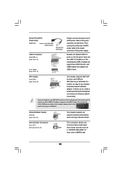
... plugged into Pin1 side of the connector. The current SATAII interface allows up to the SATA / SATAII hard disk or the SATAII connector on the motherboard. 18 Placing jumper caps over these headers and connectors. Primary IDE connector (Blue) (39-pin IDE1, see p.10, No. 10) These four Serial ... (PORT 1.1): see p.10, No. 16) (SATAII_3 (PORT 2.0): see p.10, No. 11) (SATAII_4 (PORT 2.1): see p.10 No. 8) PIN1 IDE1 connect the blue end to the motherboard connect the black end to the IDE devices 80-conductor ATA 66/100/133 cable Note: Please refer to the instruction of the SATA data...
... plugged into Pin1 side of the connector. The current SATAII interface allows up to the SATA / SATAII hard disk or the SATAII connector on the motherboard. 18 Placing jumper caps over these headers and connectors. Primary IDE connector (Blue) (39-pin IDE1, see p.10, No. 10) These four Serial ... (PORT 1.1): see p.10, No. 16) (SATAII_3 (PORT 2.0): see p.10, No. 11) (SATAII_4 (PORT 2.1): see p.10 No. 8) PIN1 IDE1 connect the blue end to the motherboard connect the black end to the IDE devices 80-conductor ATA 66/100/133 cable Note: Please refer to the instruction of the SATA data...
User Manual
Page 19
If you don't plan to use WiFi+AP function on this motherboard, this header, please refer to -use wireless local area network (WLAN) adapter. USB 2.0 Headers (9-pin USB6_7) (see p.10 No. 14) (4-pin USB8) (see p.10 No. ... can be used as a CD-ROM, DVD-ROM, TV tuner card, or MPEG card. 19 D 0 +G N D 1 USB+5V_1 PME# This header supports WiFi+AP function with ASRock WiFi-802.11g or WiFi-802.11n module, an easy-to this motherboard.
If you don't plan to use WiFi+AP function on this motherboard, this header, please refer to -use wireless local area network (WLAN) adapter. USB 2.0 Headers (9-pin USB6_7) (see p.10 No. 14) (4-pin USB8) (see p.10 No. ... can be used as a CD-ROM, DVD-ROM, TV tuner card, or MPEG card. 19 D 0 +G N D 1 USB+5V_1 PME# This header supports WiFi+AP function with ASRock WiFi-802.11g or WiFi-802.11n module, an easy-to this motherboard.
User Manual
Page 21
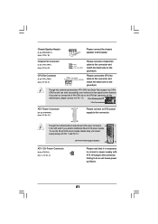
...ATX Power Connector (24-pin ATXPWR1) (see p.10, No. 31) 13 1 Please connect an ATX power supply to this connector. 24 12 Though this motherboard provides 24-pin ATX power connector, 13 1 it is necessary to connect a power supply with Pin 1 and Pin 13. 20-Pin ATX Power Supply ... No. 20) GND +12V CHA_FAN_SPEED Please connect a chassis fan cable to this connector and match the black wire to the ground pin. Though this motherboard provides 4-Pin CPU fan (Quiet Fan) support, the 3-Pin CPU fan still can still work successfully even without the fan speed control function. Failing ...
...ATX Power Connector (24-pin ATXPWR1) (see p.10, No. 31) 13 1 Please connect an ATX power supply to this connector. 24 12 Though this motherboard provides 24-pin ATX power connector, 13 1 it is necessary to connect a power supply with Pin 1 and Pin 13. 20-Pin ATX Power Supply ... No. 20) GND +12V CHA_FAN_SPEED Please connect a chassis fan cable to this connector and match the black wire to the ground pin. Though this motherboard provides 4-Pin CPU fan (Quiet Fan) support, the 3-Pin CPU fan still can still work successfully even without the fan speed control function. Failing ...

User Manual
Page 22
A. Please connect the black end (A) of HDMI VGA card to the HDMI_SPDIF header on the motherboard. white end (2-pin) C. white end (3-pin) blue black SPDIFOUT GND blue black SPDIFOUT GND blue black 22 Please connect the HDMI_SPDIF connector of HDMI_SPDIF cable ...
A. Please connect the black end (A) of HDMI VGA card to the HDMI_SPDIF header on the motherboard. white end (2-pin) C. white end (3-pin) blue black SPDIFOUT GND blue black SPDIFOUT GND blue black 22 Please connect the HDMI_SPDIF connector of HDMI_SPDIF cable ...
User Manual
Page 23
... specification, which provides SPDIF audio output to HDMI VGA card, allows the system to the wrong connector of HDMI VGA card, please refer to this motherboard, please carefully follow the below steps. •Step 1. white end (2-pin) (B) white end (3-pin) (C) Please do not connect the white end...Digital TV/projector/ LCD devices. To use HDMI function on HDMI VGA card, please refer to the user manual of HDMI_SPDIF connectors on this motherboard and the HDMI VGA card. For the pin definition of HDTV and HDMI VGA card vendor for connector usage in advance. Step 5. 2.7 ...
... specification, which provides SPDIF audio output to HDMI VGA card, allows the system to the wrong connector of HDMI VGA card, please refer to this motherboard, please carefully follow the below steps. •Step 1. white end (2-pin) (B) white end (3-pin) (C) Please do not connect the white end...Digital TV/projector/ LCD devices. To use HDMI function on HDMI VGA card, please refer to the user manual of HDMI_SPDIF connectors on this motherboard and the HDMI VGA card. For the pin definition of HDTV and HDMI VGA card vendor for connector usage in advance. Step 5. 2.7 ...

User Manual
Page 25
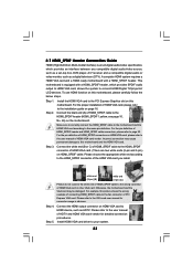
... the SATA power cable to install the SATA / SATAII hard disks. 2.9 Serial ATA (SATA) / Serial ATAII (SATAII) Hard Disks Installation This motherboard adopts NVIDIA® GeForce 6150SE / nForce 430 or GeForce 7025 / nForce 630a chipset that it cannot perform Hot Plug if the OS has been installed.../ SATAII HDDs while the system is Hot Swap Function? STEP 3: Connect one end of the SATA data cable to the motherboard's SATAII connector. What is still power-on this motherboard for SATA / SATAII Devices. STEP 1: Install the SATA / SATAII hard disks into the SATA / SATAII HDD. STEP ...
... the SATA power cable to install the SATA / SATAII hard disks. 2.9 Serial ATA (SATA) / Serial ATAII (SATAII) Hard Disks Installation This motherboard adopts NVIDIA® GeForce 6150SE / nForce 430 or GeForce 7025 / nForce 630a chipset that it cannot perform Hot Plug if the OS has been installed.../ SATAII HDDs while the system is Hot Swap Function? STEP 3: Connect one end of the SATA data cable to the motherboard's SATAII connector. What is still power-on this motherboard for SATA / SATAII Devices. STEP 1: Install the SATA / SATAII hard disks into the SATA / SATAII HDD. STEP ...

User Manual
Page 26
... to power supply Caution 1. Below operation procedure is designed only for SATA / SATAII HDD. The SATA / SATAII HDD, which are from our motherboard package. 5. Make sure to support Hot Plug and will be processed. 2. Before you process the Hot Plug: 1. A. 7-pin SATA data cable ...pin conventional power connector interfaces, the IDE 1x4-pin conventional power connector interface is indicated in the product spec on our support website: www.asrock.com 4. SATA data cable (Red) B. SATA power cable SATA 7-pin connector The SATA 15-pin power connector (Black) connect to SATA...
... to power supply Caution 1. Below operation procedure is designed only for SATA / SATAII HDD. The SATA / SATAII HDD, which are from our motherboard package. 5. Make sure to support Hot Plug and will be processed. 2. Before you process the Hot Plug: 1. A. 7-pin SATA data cable ...pin conventional power connector interfaces, the IDE 1x4-pin conventional power connector interface is indicated in the product spec on our support website: www.asrock.com 4. SATA data cable (Red) B. SATA power cable SATA 7-pin connector The SATA 15-pin power connector (Black) connect to SATA...

User Manual
Page 27
... / SATAII HDD: Points of attention, before you process the Hot Unplug: Please do follow below instruction sequence to the power supply 1x4-pin cable. the motherboard's SATAII connector. How to Hot Unplug a SATA / SATAII HDD: Points of attention, before you process the Hot Plug: Please do follow below instruction sequence to...
... / SATAII HDD: Points of attention, before you process the Hot Unplug: Please do follow below instruction sequence to the power supply 1x4-pin cable. the motherboard's SATAII connector. How to Hot Unplug a SATA / SATAII HDD: Points of attention, before you process the Hot Plug: Please do follow below instruction sequence to...
User Manual
Page 30
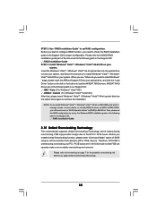
...the Windows RAID installation guide in the following path in the Support CD: .. \ RAID Installation Guide 2.15 Untied Overclocking Technology This motherboard supports Untied Overclocking Technology, which means during overclocking, but PCI / PCIE buses are in the following path in the Support CD: ... RAID functions on page 7 for proper configuration. STEP 2: Use "RAID Installation Guide" to continue the installation. " page, please insert the ASRock Support CD into the optical drive again to set up "SATA Operation Mode" to [CPU, PCIE, Async.]. Therefore, CPU FSB is untied during...
...the Windows RAID installation guide in the following path in the Support CD: .. \ RAID Installation Guide 2.15 Untied Overclocking Technology This motherboard supports Untied Overclocking Technology, which means during overclocking, but PCI / PCIE buses are in the following path in the Support CD: ... RAID functions on page 7 for proper configuration. STEP 2: Use "RAID Installation Guide" to continue the installation. " page, please insert the ASRock Support CD into the optical drive again to set up "SATA Operation Mode" to [CPU, PCIE, Async.]. Therefore, CPU FSB is untied during...

