
User Manual
Page 4
2.20 Untied Overclocking Technology 46 3 BIOS SETUP UTILITY 47 3.1 Introduction 47 3.1.1 BIOS Menu Bar 47 3.1.2 Navigation Keys 48 3.2 Main Screen 48 3.3 Smart Screen 49 3.4 Advanced Screen 50 3.4.1 CPU Configuration 50 3.4.2 Chipset Configuration 52 3.4.3 ACPI Configuration 54 3.4.4 IDE ...
2.20 Untied Overclocking Technology 46 3 BIOS SETUP UTILITY 47 3.1 Introduction 47 3.1.1 BIOS Menu Bar 47 3.1.2 Navigation Keys 48 3.2 Main Screen 48 3.3 Smart Screen 49 3.4 Advanced Screen 50 3.4.1 CPU Configuration 50 3.4.2 Chipset Configuration 52 3.4.3 ACPI Configuration 54 3.4.4 IDE ...

User Manual
Page 5
... CPU support lists on ASRock website without notice. www.asrock.com/support/index.asp 1.1 Package Contents 1 x ASRock N7AD-SLI Motherboard (ATX Form Factor: 12.0-in x 8.2-in, 30.5 cm x 20.8 cm) 1 x ASRock SLI_Bridge_2S Card 1 x ASRock SLI/XFire Switch Card 1 x ASRock N7AD-SLI Quick Installation Guide 1 x ASRock N7AD-SLI Support CD 1 x .... Chapter 1 Introduction Thank you are using. It delivers excellent performance with robust design conforming to ASRock's commitment to BIOS setup and information of the motherboard and step-by-step guide to change without further notice. Because the...
... CPU support lists on ASRock website without notice. www.asrock.com/support/index.asp 1.1 Package Contents 1 x ASRock N7AD-SLI Motherboard (ATX Form Factor: 12.0-in x 8.2-in, 30.5 cm x 20.8 cm) 1 x ASRock SLI_Bridge_2S Card 1 x ASRock SLI/XFire Switch Card 1 x ASRock N7AD-SLI Quick Installation Guide 1 x ASRock N7AD-SLI Support CD 1 x .... Chapter 1 Introduction Thank you are using. It delivers excellent performance with robust design conforming to ASRock's commitment to BIOS setup and information of the motherboard and step-by-step guide to change without further notice. Because the...
User Manual
Page 7
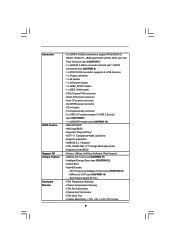
... 9) - 1 x USB/WiFi header (see CAUTION 12) - CPU Temperature Sensing - CPU Fan Tachometer - CPU/Chassis FAN connector - 24 pin ATX power connector - 8 pin 12V power connector - SLI/XFIRE power connector - Supports jumperfree - Intelligent Energy Saver (see CAUTION 10) - 8Mb AMI BIOS - CPU Frequency Stepless Control (see CAUTION 14) - ASRock U-COP (see CAUTION 13) -
... 9) - 1 x USB/WiFi header (see CAUTION 12) - CPU Temperature Sensing - CPU Fan Tachometer - CPU/Chassis FAN connector - 24 pin ATX power connector - 8 pin 12V power connector - SLI/XFIRE power connector - Supports jumperfree - Intelligent Energy Saver (see CAUTION 10) - 8Mb AMI BIOS - CPU Frequency Stepless Control (see CAUTION 14) - ASRock U-COP (see CAUTION 13) -

User Manual
Page 8
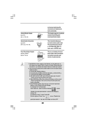
...eSATAII installation procedures. 9. Please check the table on page 34 for proper connection. 7. Please read the installation guide of ASRock SLI/XFire Switch Card. Power Management for details. 3. OS - FCC, CE, WHQL * For detailed product information, please visit our website: http...® VistaTM 64-bit with 64-bit CPU, there is a certain risk involved with overclocking, including adjusting the setting in the BIOS, applying Untied Overclocking Technology, or using the thirdparty overclocking tools. Before installing SATAII hard disk to SATAII connector, please read "Untied ...
...eSATAII installation procedures. 9. Please check the table on page 34 for proper connection. 7. Please read the installation guide of ASRock SLI/XFire Switch Card. Power Management for details. 3. OS - FCC, CE, WHQL * For detailed product information, please visit our website: http...® VistaTM 64-bit with 64-bit CPU, there is a certain risk involved with overclocking, including adjusting the setting in the BIOS, applying Untied Overclocking Technology, or using the thirdparty overclocking tools. Before installing SATAII hard disk to SATAII connector, please read "Untied ...

User Manual
Page 11
...1394 USB 2.0 T: USB0 B: USB1 Top: RJ-45 CPU_FAN1 USB8_9 1 USB6_7 1 NVIDIA nForce 740i SLI Chipset SLI/XFIRE_PWR1 Top: LINE IN Center: FRONT Bottom: MIC IN 35 8Mb BIOS 34 PCIE1 N7AD-SLI RoHS LAN PHY 33 PCIE2 DDR2 800 Dual Channel 32 31 30 29 28 27 26 Super I/O ...(Dual Channel B: DDRII_2, DDRII_4; Orange) 26 Internal Audio Connector: CD1 (Black) 8 ATX Power Connector (ATXPWR1) 27 PCI Slots (PCI1-2) 9 SPI BIOS Chip 28 HDMI_SPDIF Header 10 SATAII Connector (SATAII_2 (Port1), Red) (HDMI_SPDIF1, Yellow) 11 SATAII Connector (SATAII_4 (Port3), Red) 29 PCI Express x16 Slot ...
...1394 USB 2.0 T: USB0 B: USB1 Top: RJ-45 CPU_FAN1 USB8_9 1 USB6_7 1 NVIDIA nForce 740i SLI Chipset SLI/XFIRE_PWR1 Top: LINE IN Center: FRONT Bottom: MIC IN 35 8Mb BIOS 34 PCIE1 N7AD-SLI RoHS LAN PHY 33 PCIE2 DDR2 800 Dual Channel 32 31 30 29 28 27 26 Super I/O ...(Dual Channel B: DDRII_2, DDRII_4; Orange) 26 Internal Audio Connector: CD1 (Black) 8 ATX Power Connector (ATXPWR1) 27 PCI Slots (PCI1-2) 9 SPI BIOS Chip 28 HDMI_SPDIF Header 10 SATAII Connector (SATAII_2 (Port1), Red) (HDMI_SPDIF1, Yellow) 11 SATAII Connector (SATAII_4 (Port3), Red) 29 PCI Express x16 Slot ...

User Manual
Page 26
... clear and reset the system parameters to short pin2 and pin3 on PCI Express VGA card, you update the BIOS. If you need to clear the CMOS when you just finish updating the BIOS, you to enable +5VSB (standby) for PS/2 or USB wake up the system first, and then shut it...
... clear and reset the system parameters to short pin2 and pin3 on PCI Express VGA card, you update the BIOS. If you need to clear the CMOS when you just finish updating the BIOS, you to enable +5VSB (standby) for PS/2 or USB wake up the system first, and then shut it...
User Manual
Page 29
.... Enter Advanced Settings, and then select Chipset Configuration. This header supports an optional wireless transmitting and receiving infrared module. Connect Mic_IN (MIC) to [Enabled]. D. Enter BIOS Setup Utility. Set the Front Panel Control option from sound sources such as below: A. MIC_RET and OUT_RET are for front panel audio cable that allows...
.... Enter Advanced Settings, and then select Chipset Configuration. This header supports an optional wireless transmitting and receiving infrared module. Connect Mic_IN (MIC) to [Enabled]. D. Enter BIOS Setup Utility. Set the Front Panel Control option from sound sources such as below: A. MIC_RET and OUT_RET are for front panel audio cable that allows...

User Manual
Page 34
...SATAII hard disk. Please refer to page 42 to 46 for detailed information of the advantageous transfer speed and the facilitating mobile capability, in BIOS setup to exchange drives easily. If you to IDE mode. Therefore, you may affect the Hot Plug function that enables you set "SATA... option in working condition. 2. For example, with eSATAII devices. eSATAII allows you want to 480Mb/s, and for external interface. Currently, on and in BIOS setup to 3.0Gb/s, and the convenient mobility like USB. If you to enjoy the SATAII function provided by the I/O of USB 2.0 is up to...
...SATAII hard disk. Please refer to page 42 to 46 for detailed information of the advantageous transfer speed and the facilitating mobile capability, in BIOS setup to exchange drives easily. If you to IDE mode. Therefore, you may affect the Hot Plug function that enables you set "SATA... option in working condition. 2. For example, with eSATAII devices. eSATAII allows you want to 480Mb/s, and for external interface. Currently, on and in BIOS setup to 3.0Gb/s, and the convenient mobility like USB. If you to enjoy the SATAII function provided by the I/O of USB 2.0 is up to...

User Manual
Page 42
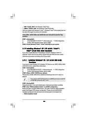
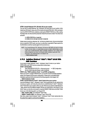
... key, and then a window for WindowsXP/XP64 2. Using SATA / SATAII HDDs and eSATAII devices with NCQ and Hot Plug functions STEP 1: Set Up BIOS. Set the "SATA Operation Mode" option to your SATA / SATAII HDDs without RAID functions, please follow below steps. STEP 2: Make a SATA / ...you choose and the OS you see these messages, Please choose: 1. Then, the drivers compatible to [IDE]. A. A. Insert the ASRock Support CD into the floppy drive. When you install. Generate AHCI Driver diskette for boot devices selection appears. Select your optical drive first.
... key, and then a window for WindowsXP/XP64 2. Using SATA / SATAII HDDs and eSATAII devices with NCQ and Hot Plug functions STEP 1: Set Up BIOS. Set the "SATA Operation Mode" option to your SATA / SATAII HDDs without RAID functions, please follow below steps. STEP 2: Make a SATA / ...you choose and the OS you see these messages, Please choose: 1. Then, the drivers compatible to [IDE]. A. A. Insert the ASRock Support CD into the floppy drive. When you install. Generate AHCI Driver diskette for boot devices selection appears. Select your optical drive first.

User Manual
Page 43
...STEP 4: Install Windows® XP / XP 64-bit OS on your SATA / SATAII HDDs without NCQ and Hot Plug functions STEP 1: Set Up BIOS. NVIDIA nForce Storage Controller (required) Windows XP B. B. When you see "Where do you want to install Windows? The drivers are in the following ... to install Windows® XP / XP 64-bit on your system. " page, please insert the ASRock Support CD into the optical drive to boot your system, and follow below : A. Enter BIOS SETUP UTILITY Advanced screen IDE Configuration. You can start to load the NVIDIA® AHCI drivers. A. ...
...STEP 4: Install Windows® XP / XP 64-bit OS on your SATA / SATAII HDDs without NCQ and Hot Plug functions STEP 1: Set Up BIOS. NVIDIA nForce Storage Controller (required) Windows XP B. B. When you see "Where do you want to install Windows? The drivers are in the following ... to install Windows® XP / XP 64-bit on your system. " page, please insert the ASRock Support CD into the optical drive to boot your system, and follow below : A. Enter BIOS SETUP UTILITY Advanced screen IDE Configuration. You can start to load the NVIDIA® AHCI drivers. A. ...
User Manual
Page 44
... install Windows® XP / Windows® XP 64-bit on your SATA / SATAII HDDs with RAID functions, please follow step 1 to the BIOS RAID installation guide part of the document in the following section 2.18.1 step 2 on your SATA / SATAII HDDs with RAID functions, please follow... below steps. STEP 4: Use "RAID Installation Guide" to set up the BIOS option "SATA Operation Mode" to check the RAID installation guide in the Support CD: .. \ RAID Installation Guide 44 A. Please make a SATA / SATAII ...
... install Windows® XP / Windows® XP 64-bit on your SATA / SATAII HDDs with RAID functions, please follow step 1 to the BIOS RAID installation guide part of the document in the following section 2.18.1 step 2 on your SATA / SATAII HDDs with RAID functions, please follow... below steps. STEP 4: Use "RAID Installation Guide" to set up the BIOS option "SATA Operation Mode" to check the RAID installation guide in the Support CD: .. \ RAID Installation Guide 44 A. Please make a SATA / SATAII ...
User Manual
Page 45
... Advanced screen IDE Configuration. " page, please insert the ASRock Support CD into your optical drive, and click the "Load Driver" button on the left on your system. You can start to configure RAID function, you want to [RAID] in BIOS first. After reading the floppy disk, the drivers will...; VistaTM / Windows® VistaTM 64-bit OS on your SATA / SATAII HDDs with RAID functions, please follow below : A. Please refer to the BIOS RAID installation guide part of Windows® setup, press F6 to continue the installation. 45 Insert the Windows® VistaTM / Windows® VistaTM 64-...
... Advanced screen IDE Configuration. " page, please insert the ASRock Support CD into your optical drive, and click the "Load Driver" button on the left on your system. You can start to configure RAID function, you want to [RAID] in BIOS first. After reading the floppy disk, the drivers will...; VistaTM / Windows® VistaTM 64-bit OS on your SATA / SATAII HDDs with RAID functions, please follow below : A. Please refer to the BIOS RAID installation guide part of Windows® setup, press F6 to continue the installation. 45 Insert the Windows® VistaTM / Windows® VistaTM 64-...

User Manual
Page 46
..., convert, delete, or rebuild) RAID functions on page 8 for the possible overclocking risk before you enable Untied Overclocking function, please enter "Overclock Mode" option of BIOS setup to set the selection from [Auto] to [RAID] in the fixed mode so that FSB can operate under a more stable overclocking environment. Therefore, CPU... the Support CD: .. \ RAID Installation Guide 2 . 2 0 Untied Overclocking Technology This motherboard supports Untied Overclocking Technology, which means during overclocking, but PCI / PCIE buses are in BIOS first.
..., convert, delete, or rebuild) RAID functions on page 8 for the possible overclocking risk before you enable Untied Overclocking function, please enter "Overclock Mode" option of BIOS setup to set the selection from [Auto] to [RAID] in the fixed mode so that FSB can operate under a more stable overclocking environment. Therefore, CPU... the Support CD: .. \ RAID Installation Guide 2 . 2 0 Untied Overclocking Technology This motherboard supports Untied Overclocking Technology, which means during overclocking, but PCI / PCIE buses are in BIOS first.

User Manual
Page 47
... is constantly being updated, the following selections: Main To set up the system time/date information Advanced To set up the advanced BIOS features H/W Monitor To display current hardware status Boot To set up the default system device to locate and load the Operating System Security To set ... for reference purpose only, and they may not exactly match what you start up the security features Exit To exit the current screen or the BIOS SETUP UTILITY Use < > key or < > key to choose among the selections on the menu bar, and then press to enter the...
... is constantly being updated, the following selections: Main To set up the system time/date information Advanced To set up the advanced BIOS features H/W Monitor To display current hardware status Boot To set up the default system device to locate and load the Operating System Security To set ... for reference purpose only, and they may not exactly match what you start up the security features Exit To exit the current screen or the BIOS SETUP UTILITY Use < > key or < > key to choose among the selections on the menu bar, and then press to enter the...

User Manual
Page 48
... this item to specify the system date. 48 3.1.2Navigation Keys Please check the following table for all the settings To save changes and exit the BIOS SETUP UTILITY To jump to the Exit Screen or exit the current screen 3.2 Main Screen When you enter the... UTILITY Main Smart Advanced H/W Monitor Boot Security Exit System Overview System Time System Date [14:00:09] [Tue 09/30/2008] BIOS Version : N7AD-SLI P1.0 Processor Type : Intel (R) Core (TM) 2 CPU 6600 @ 2.40GHz (64bit) Processor Speed : 2400MHz Microcode Update : 6F6/CB Cache Size : 4096KB Total Memory DDRII1 DDRII2 DDRII3 ...
... this item to specify the system date. 48 3.1.2Navigation Keys Please check the following table for all the settings To save changes and exit the BIOS SETUP UTILITY To jump to the Exit Screen or exit the current screen 3.2 Main Screen When you enter the... UTILITY Main Smart Advanced H/W Monitor Boot Security Exit System Overview System Time System Date [14:00:09] [Tue 09/30/2008] BIOS Version : N7AD-SLI P1.0 Processor Type : Intel (R) Core (TM) 2 CPU 6600 @ 2.40GHz (64bit) Processor Speed : 2400MHz Microcode Update : 6F6/CB Cache Size : 4096KB Total Memory DDRII1 DDRII2 DDRII3 ...

User Manual
Page 49
... be used for all system configurations. Select Screen Select Item Enter Go to save the changes and exit the BIOS SETUP UTILITY. Load BIOS Defaults Load BIOS default values for this operation. If system boot failure occurs after loading, please resume optimal default settings. 3.3 Smart...and Exit ESC Exit v02.54 (C) Copyright 1985-2005, American Megatrends, Inc. BIOS SETUP UTILITY Main Smart Advanced H/W Monitor Boot Security Exit Smart Settings Save Changes and Exit Load BIOS Defaults Load Performance Setup Default (IDE/SATA) Load Performance Setup AHCI Mode Load Performance...
... be used for all system configurations. Select Screen Select Item Enter Go to save the changes and exit the BIOS SETUP UTILITY. Load BIOS Defaults Load BIOS default values for this operation. If system boot failure occurs after loading, please resume optimal default settings. 3.3 Smart...and Exit ESC Exit v02.54 (C) Copyright 1985-2005, American Megatrends, Inc. BIOS SETUP UTILITY Main Smart Advanced H/W Monitor Boot Security Exit Smart Settings Save Changes and Exit Load BIOS Defaults Load Performance Setup Default (IDE/SATA) Load Performance Setup AHCI Mode Load Performance...

User Manual
Page 50
... Select Item Change Option General Help Load Defaults Save and Exit Exit v02.54 (C) Copyright 1985-2005, American Megatrends, Inc. BIOS SETUP UTILITY Main Smart Advanced H/W Monitor Boot Security Exit Advanced Settings WARNING : Setting wrong values in this to Sub Screen F1...is [Auto]. Overclock Mode Use this section may cause system to malfunction. 3.4 Advanced Screen In this option to malfunction. 3.4.1CPU Configuration BIOS SETUP UTILITY Advanced CPU Configuration Overclock Mode CPU Frequency (MHz) PCIE Frequency (MHz) Boot Failure Guard CPU Spectrum PCIE Spectrum SATA Spectrum...
... Select Item Change Option General Help Load Defaults Save and Exit Exit v02.54 (C) Copyright 1985-2005, American Megatrends, Inc. BIOS SETUP UTILITY Main Smart Advanced H/W Monitor Boot Security Exit Advanced Settings WARNING : Setting wrong values in this to Sub Screen F1...is [Auto]. Overclock Mode Use this section may cause system to malfunction. 3.4 Advanced Screen In this option to malfunction. 3.4.1CPU Configuration BIOS SETUP UTILITY Advanced CPU Configuration Overclock Mode CPU Frequency (MHz) PCIE Frequency (MHz) Boot Failure Guard CPU Spectrum PCIE Spectrum SATA Spectrum...
User Manual
Page 52
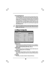
... need to set this option is Intel's new power saving technology. Please note that enabling this item to [Disable] if above issue occurs. 3.4.2Chipset Configuration BIOS SETUP UTILITY Advanced Chipset Configuration DRAM Frequency Flexibility Option Memory Timings Onboard LAN Onboard IDE and 1394 Onboard HD Audio Front Panel Primary Graphics Adapter...
... need to set this option is Intel's new power saving technology. Please note that enabling this item to [Disable] if above issue occurs. 3.4.2Chipset Configuration BIOS SETUP UTILITY Advanced Chipset Configuration DRAM Frequency Flexibility Option Memory Timings Onboard LAN Onboard IDE and 1394 Onboard HD Audio Front Panel Primary Graphics Adapter...
User Manual
Page 53
... is [Disabled]. The default value of this feature is [Auto]. GTLREF Voltage Use this to select Chipset Voltage. The default value is [PCI]. Besides the BIOS option, you to enable this function, please set this feature is [Auto]. If you select [Auto], the onboard HD Audio will be disabled when PCI...
... is [Disabled]. The default value of this feature is [Auto]. GTLREF Voltage Use this to select Chipset Voltage. The default value is [PCI]. Besides the BIOS option, you to enable this function, please set this feature is [Auto]. If you select [Auto], the onboard HD Audio will be disabled when PCI...

User Manual
Page 54
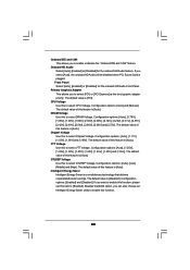
..., American Megatrends, Inc. The default value is selected, the AC/power resumes and the system starts to enable or disable ACPI HPET Table. 3.4.3ACPI Configuration BIOS SETUP UTILITY Advanced ACPI Configuration Suspend To RAM Restore on the system. Suspend to RAM Use this item to boot up when the power recovers.
..., American Megatrends, Inc. The default value is selected, the AC/power resumes and the system starts to enable or disable ACPI HPET Table. 3.4.3ACPI Configuration BIOS SETUP UTILITY Advanced ACPI Configuration Suspend To RAM Restore on the system. Suspend to RAM Use this item to boot up when the power recovers.


