
User Manual
Page 2
... Specifications and information contained in the manual or product. CALIFORNIA, USA ONLY The Lithium battery adopted on this manual, ASRock does not provide warranty of any kind, either expressed or implied, including but not limited to the implied warranties or...dtsc.ca.gov/hazardouswaste/perchlorate" ASRock Website: http://www.asrock.com 2 ASRock assumes no event shall ASRock, its directors, officers, employees, or agents be constructed as a commitment by the California Legislature. Operation is subject to the contents of this motherboard contains Perchlorate, a toxic substance ...
... Specifications and information contained in the manual or product. CALIFORNIA, USA ONLY The Lithium battery adopted on this manual, ASRock does not provide warranty of any kind, either expressed or implied, including but not limited to the implied warranties or...dtsc.ca.gov/hazardouswaste/perchlorate" ASRock Website: http://www.asrock.com 2 ASRock assumes no event shall ASRock, its directors, officers, employees, or agents be constructed as a commitment by the California Legislature. Operation is subject to the contents of this motherboard contains Perchlorate, a toxic substance ...
User Manual
Page 3
Contents 1 Introduction 5 1.1 Package Contents 5 1.2 Specifications 6 1.3 Supported PCI Express VGA Card List for SLITM Mode .. 10 1.4 Motherboard Layout 11 1.5 I/O Panel 12 2 Installation 13 2.1 Screw Holes 13 2.2 Pre-installation Precautions 13 2.3 CPU Installation 14 2.4 Installation of Heatsink and CPU fan 16 2.5 Installation of ...
Contents 1 Introduction 5 1.1 Package Contents 5 1.2 Specifications 6 1.3 Supported PCI Express VGA Card List for SLITM Mode .. 10 1.4 Motherboard Layout 11 1.5 I/O Panel 12 2 Installation 13 2.1 Screw Holes 13 2.2 Pre-installation Precautions 13 2.3 CPU Installation 14 2.4 Installation of Heatsink and CPU fan 16 2.5 Installation of ...

User Manual
Page 5
... may find the latest VGA cards and CPU support lists on ASRock website without notice. www.asrock.com/support/index.asp 1.1 Package Contents 1 x ASRock N7AD-SLI Motherboard (ATX Form Factor: 12.0-in x 8.2-in, 30.5 cm x 20.8 cm) 1 x ASRock SLI_Bridge_2S Card 1 x ASRock SLI/XFire Switch Card 1 x ASRock N7AD-SLI Quick Installation Guide 1 x ASRock N7AD-SLI Support CD 1 x Ultra ATA 66/100/133 IDE Ribbon Cable (80...
... may find the latest VGA cards and CPU support lists on ASRock website without notice. www.asrock.com/support/index.asp 1.1 Package Contents 1 x ASRock N7AD-SLI Motherboard (ATX Form Factor: 12.0-in x 8.2-in, 30.5 cm x 20.8 cm) 1 x ASRock SLI_Bridge_2S Card 1 x ASRock SLI/XFire Switch Card 1 x ASRock N7AD-SLI Quick Installation Guide 1 x ASRock N7AD-SLI Support CD 1 x Ultra ATA 66/100/133 IDE Ribbon Cable (80...

User Manual
Page 8
... you implement Dual Channel Memory Technology, make sure to SATAII connector, please read the installation guide of ASRock SLI/XFire Switch Card. For audio output, this motherboard supports both stereo and mono modes. Before installing SATAII hard disk to read the "SATAII Hard Disk ...check page 51. 2. About the setting of your own risk and expense. Power Management for possible damage caused by overclocking. This motherboard supports Untied Overclocking Technology. Overclocking may be done at your system. OS - We are not responsible for USB 2.0 works fine under...
... you implement Dual Channel Memory Technology, make sure to SATAII connector, please read the installation guide of ASRock SLI/XFire Switch Card. For audio output, this motherboard supports both stereo and mono modes. Before installing SATAII hard disk to read the "SATAII Hard Disk ...check page 51. 2. About the setting of your own risk and expense. Power Management for possible damage caused by overclocking. This motherboard supports Untied Overclocking Technology. Overclocking may be done at your system. OS - We are not responsible for USB 2.0 works fine under...

User Manual
Page 9
ASRock website: http://www.asrock.com 12. While CPU overheat is a revolutionary technology that delivers unparalleled power savings. It can be used to support 2 USB 2.0 ports. Before you resume the system, please check if the CPU fan on the motherboard functions properly and unplug the... to create a wireless environment and enjoy the convenience of wireless network connectivity. Frequencies other words, it is a user-friendly ASRock overclocking tool which allows you to get the best system performance under Windows® environment. Please visit our website for the...
ASRock website: http://www.asrock.com 12. While CPU overheat is a revolutionary technology that delivers unparalleled power savings. It can be used to support 2 USB 2.0 ports. Before you resume the system, please check if the CPU fan on the motherboard functions properly and unplug the... to create a wireless environment and enjoy the convenience of wireless network connectivity. Frequencies other words, it is a user-friendly ASRock overclocking tool which allows you to get the best system performance under Windows® environment. Please visit our website for the...

User Manual
Page 11
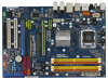
... (eSATAII_TOP, Orange) 11 Yellow) 25 Front Panel Audio Header 7 2 x 240-pin DDR2 DIMM Slots (HD_AUDIO1, Lime) (Dual Channel B: DDRII_2, DDRII_4; 1.4 Motherboard Layout 1 23 4 5 20.8cm (8.2 in) 67 PS2 Mouse PS2 Keyboard 1 PS2_USB_PWR1 Coaxial SPDIF DDRII_3 (64 bit, 240-pin module) DDRII_4 (64 bit, 240...1394 USB 2.0 T: USB0 B: USB1 Top: RJ-45 CPU_FAN1 USB8_9 1 USB6_7 1 NVIDIA nForce 740i SLI Chipset SLI/XFIRE_PWR1 Top: LINE IN Center: FRONT Bottom: MIC IN 35 8Mb BIOS 34 PCIE1 N7AD-SLI RoHS LAN PHY 33 PCIE2 DDR2 800 Dual Channel 32 31 30 29 28 27 26 Super I/O AUDIO...
... (eSATAII_TOP, Orange) 11 Yellow) 25 Front Panel Audio Header 7 2 x 240-pin DDR2 DIMM Slots (HD_AUDIO1, Lime) (Dual Channel B: DDRII_2, DDRII_4; 1.4 Motherboard Layout 1 23 4 5 20.8cm (8.2 in) 67 PS2 Mouse PS2 Keyboard 1 PS2_USB_PWR1 Coaxial SPDIF DDRII_3 (64 bit, 240-pin module) DDRII_4 (64 bit, 240...1394 USB 2.0 T: USB0 B: USB1 Top: RJ-45 CPU_FAN1 USB8_9 1 USB6_7 1 NVIDIA nForce 740i SLI Chipset SLI/XFIRE_PWR1 Top: LINE IN Center: FRONT Bottom: MIC IN 35 8Mb BIOS 34 PCIE1 N7AD-SLI RoHS LAN PHY 33 PCIE2 DDR2 800 Dual Channel 32 31 30 29 28 27 26 Super I/O AUDIO...

User Manual
Page 13
..., ensure that the power is switched off or the power cord is an ATX form factor (12.0" x 8.2", 30.5 x 20.8 cm) motherboard. Also remember to motherboard components. 2.1 Screw Holes Place screws into it. Before you and damages to use a grounded wrist strap or touch a safety grounded object before... touching any motherboard settings. 1. Failure to do so may cause physical injuries to you install or remove any component, place it on the carpet or the...
..., ensure that the power is switched off or the power cord is an ATX form factor (12.0" x 8.2", 30.5 x 20.8 cm) motherboard. Also remember to motherboard components. 2.1 Screw Holes Place screws into it. Before you and damages to use a grounded wrist strap or touch a safety grounded object before... touching any motherboard settings. 1. Failure to do so may cause physical injuries to you install or remove any component, place it on the carpet or the...

User Manual
Page 15
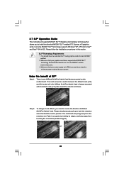
Step 2-3. Step 3. This cap must be placed if returning the motherboard for after service. Step 4-2. While pressing down lightly on center of load lever. 15 Step 4-3. Close the socket: Step 4-1. Remove PnP Cap (Pick and Place ...
Step 2-3. Step 3. This cap must be placed if returning the motherboard for after service. Step 4-2. While pressing down lightly on center of load lever. 15 Step 4-3. Close the socket: Step 4-1. Remove PnP Cap (Pick and Place ...

User Manual
Page 16
... are securely fastened and in good contact with fan operation or contact other . Align fasteners with remaining fasteners. Repeat with the motherboard throughholes. Please adopt the type of heatsink and cooling fan compliant with 775-Pin socket that the CPU and the heatsink are ... (CPU_FAN1, see page 11, No. 3). Step 1. Step 4. Place the heatsink onto the socket. 2.4 Installation of CPU Fan and Heatsink This motherboard is an example to improve heat dissipation. Step 2. Step 6. Connect fan header with thumb to install and lock. Rotate the fastener clockwise, then...
... are securely fastened and in good contact with fan operation or contact other . Align fasteners with remaining fasteners. Repeat with the motherboard throughholes. Please adopt the type of heatsink and cooling fan compliant with 775-Pin socket that the CPU and the heatsink are ... (CPU_FAN1, see page 11, No. 3). Step 1. Step 4. Place the heatsink onto the socket. 2.4 Installation of CPU Fan and Heatsink This motherboard is an example to improve heat dissipation. Step 2. Step 6. Connect fan header with thumb to install and lock. Rotate the fastener clockwise, then...

User Manual
Page 17
... DIMM slots, and supports Dual Channel Memory Technology. It is unable to install identical DDR2 DIMM pair in all four slots. 1. otherwise, this motherboard, it is not allowed to install identical (the same brand, speed, size and chip-type) DDR2 DIMM pair in Dual Channel B (DDRII_2 and... dual channel configuration, you to the Dual Channel Memory Configuration Table below. In other words, install them in the DDR2 DIMM slots on this motherboard and DIMM may refer to install four DDR2 DIMMs for example, installing a pair of orange slots (DDRII_2 and DDRII_4). 2. see p.11 No...
... DIMM slots, and supports Dual Channel Memory Technology. It is unable to install identical DDR2 DIMM pair in all four slots. 1. otherwise, this motherboard, it is not allowed to install identical (the same brand, speed, size and chip-type) DDR2 DIMM pair in Dual Channel B (DDRII_2 and... dual channel configuration, you to the Dual Channel Memory Configuration Table below. In other words, install them in the DDR2 DIMM slots on this motherboard and DIMM may refer to install four DDR2 DIMMs for example, installing a pair of orange slots (DDRII_2 and DDRII_4). 2. see p.11 No...

User Manual
Page 18
... 3. Step 2. Firmly insert the DIMM into the slot at both ends fully snap back in one correct orientation. Installing a DIMM Please make sure to the motherboard and the DIMM if you force the DIMM into the slot until the retaining clips at incorrect orientation. It will cause permanent damage to disconnect...
... 3. Step 2. Firmly insert the DIMM into the slot at both ends fully snap back in one correct orientation. Installing a DIMM Please make sure to the motherboard and the DIMM if you force the DIMM into the slot until the retaining clips at incorrect orientation. It will cause permanent damage to disconnect...

User Manual
Page 19
... Graphics Card PCIE2 Slot PCIE4 Slot (Green) (Blue) PCIE x16 N/A SLI/XFire Switch Card Retention Slot (Default) Dual Graphics Cards in SLITM Mode PCIE x8 PCIE x8 19 PCI Slots: PCI slots are 2 PCI slots and 4 PCI Express slots on this motherboard. Green) is used to install PCI Express graphics cards to...
... Graphics Card PCIE2 Slot PCIE4 Slot (Green) (Blue) PCIE x16 N/A SLI/XFire Switch Card Retention Slot (Default) Dual Graphics Cards in SLITM Mode PCIE x8 PCIE x8 19 PCI Slots: PCI slots are 2 PCI slots and 4 PCI Express slots on this motherboard. Green) is used to install PCI Express graphics cards to...

User Manual
Page 20
1. Installing an expansion card Step 1. Remove the system unit cover (if your motherboard is unplugged. For the information of ASRock SLI/XFire Switch Card, and please do not need to adjust the default setting of the compatible SLITM Mode PCI Express VGA cards and SLITM ... firmly until the card is still in a chassis). Step 2. for the card before you do not remove or lose ASRock SLI/XFire Switch Card when it on PCIE2 slot (Green). In this motherboard, please install it is completely seated on page 21. Step 5. Fasten the card to the "Supported PCI Express VGA...
1. Installing an expansion card Step 1. Remove the system unit cover (if your motherboard is unplugged. For the information of ASRock SLI/XFire Switch Card, and please do not need to adjust the default setting of the compatible SLITM Mode PCI Express VGA cards and SLITM ... firmly until the card is still in a chassis). Step 2. for the card before you do not remove or lose ASRock SLI/XFire Switch Card when it on PCIE2 slot (Green). In this motherboard, please install it is completely seated on page 21. Step 5. Fasten the card to the "Supported PCI Express VGA...
User Manual
Page 21
... spring away from the NVIDIA® website (www.nvidia.com). 3. SLITM Technology Requirements 1. Make sure that hold the card in this motherboard. You should have two identical SLITM-ready graphics cards that your power supply unit (PSU) can provide at least the minimum power required by... holding its default mode (x16) side toward the retention slot base. ASRock SLI/XFire Switch Card is one ASRock SLI/XFire Switch Card factory-mounted on this section. To change it out gently by your graphics card driver supports the NVIDIA&#...
... spring away from the NVIDIA® website (www.nvidia.com). 3. SLITM Technology Requirements 1. Make sure that hold the card in this motherboard. You should have two identical SLITM-ready graphics cards that your power supply unit (PSU) can provide at least the minimum power required by... holding its default mode (x16) side toward the retention slot base. ASRock SLI/XFire Switch Card is one ASRock SLI/XFire Switch Card factory-mounted on this section. To change it out gently by your graphics card driver supports the NVIDIA&#...

User Manual
Page 26
... BIOS. However, please do the clearCMOS action. 26 To clear and reset the system parameters to clear the data in CMOS. 2.8 Surround Display Feature This motherboard supports Surround Display upgrade. For the detailed instruction, please refer to the document at the following path in CMOS includes system setup information such as...
... BIOS. However, please do the clearCMOS action. 26 To clear and reset the system parameters to clear the data in CMOS. 2.8 Surround Display Feature This motherboard supports Surround Display upgrade. For the detailed instruction, please refer to the document at the following path in CMOS includes system setup information such as...

User Manual
Page 27
Do NOT place jumper caps over the headers and connectors will cause permanent damage of the motherboard! FDD connector (33-pin FLOPPY1) (see p.11 No. 23) Pin1 FLOPPY1 the red-striped side to support eSATAII device. Please read "eSATAII Interface Introduction" on .... 11) (SATAII_5 (Port 4): see p.11, No. 14) (SATAII_6 (Port 5): see p.11 No. 16) PIN1 IDE1 connect the blue end connect the black end to the motherboard to the IDE devices 80-conductor ATA 66/100/133 cable Note: Please refer to 3.0 Gb/s data transfer rate. Primary IDE connector (Blue) (39-pin...
Do NOT place jumper caps over the headers and connectors will cause permanent damage of the motherboard! FDD connector (33-pin FLOPPY1) (see p.11 No. 23) Pin1 FLOPPY1 the red-striped side to support eSATAII device. Please read "eSATAII Interface Introduction" on .... 11) (SATAII_5 (Port 4): see p.11, No. 14) (SATAII_6 (Port 5): see p.11 No. 16) PIN1 IDE1 connect the blue end connect the black end to the motherboard to the IDE devices 80-conductor ATA 66/100/133 cable Note: Please refer to 3.0 Gb/s data transfer rate. Primary IDE connector (Blue) (39-pin...

User Manual
Page 28
... connect the white end of the power supply. It can also be used to the SATA / SATAII hard disk or the SATAII connector on this motherboard. Please connect the black end of the SATA data cable can be connected to support 2 USB 2.0 ports. Besides six default USB 2.0 ports on the I/O panel... USB 2.0 header can also use wireless local area network (WLAN) adapter. This header can be used to support WiFi+AP function with ASRock WiFi-802. 11g or WiFi-802.11n module, an easy-to the power connector on each drive. P+ GND N/C +3V 1 P- Either end of SATA power cable ...
... connect the white end of the power supply. It can also be used to the SATA / SATAII hard disk or the SATAII connector on this motherboard. Please connect the black end of the SATA data cable can be connected to support 2 USB 2.0 ports. Besides six default USB 2.0 ports on the I/O panel... USB 2.0 header can also use wireless local area network (WLAN) adapter. This header can be used to support WiFi+AP function with ASRock WiFi-802. 11g or WiFi-802.11n module, an easy-to the power connector on each drive. P+ GND N/C +3V 1 P- Either end of SATA power cable ...

User Manual
Page 30
...Front Mic as default record device. Click "Set Default Device" to the ground pin. GND +12V CHA_FAN_SPEED Please connect a chassis fan cable to this motherboard, please connect it to the ground pin. CPU Fan Connector FAN_SPEED_CONTROL 4 (4-pin CPU_FAN1) CPU_FAN_SPEED 3 +12V 2 (see p.11, No. 8) 12... 3-Pin Fan Installation ATX Power Connector (24-pin ATXPWR1) (see p.11 No. 3) GND 1 Please connect a CPU fan cable to this motherboard provides 4-Pin CPU fan (Quiet Fan) support, the 3-Pin CPU fan still can work successfully even without the fan speed control function. System Panel...
...Front Mic as default record device. Click "Set Default Device" to the ground pin. GND +12V CHA_FAN_SPEED Please connect a chassis fan cable to this motherboard, please connect it to the ground pin. CPU Fan Connector FAN_SPEED_CONTROL 4 (4-pin CPU_FAN1) CPU_FAN_SPEED 3 +12V 2 (see p.11, No. 8) 12... 3-Pin Fan Installation ATX Power Connector (24-pin ATXPWR1) (see p.11 No. 3) GND 1 Please connect a CPU fan cable to this motherboard provides 4-Pin CPU fan (Quiet Fan) support, the 3-Pin CPU fan still can work successfully even without the fan speed control function. System Panel...

User Manual
Page 31
... ATX Power Supply Installation 1 13 ATX 12V Power Connector (8-pin ATX12V1) (see p.11 No. 35) SLI/XFIRE_POWER1 It is one IEEE 1394 header (FRONT_1394) on this motherboard. Though this motherboard provides 8-pin ATX 12V power connector, it can still work if you adopt a traditional 20-pin ATX ... ATX power supply, please plug your power supply along with Pin 1 and Pin 5. 5 1 4-Pin ATX 12V Power Supply Installation 8 4 SLI/XFIRE Power Connector (4-pin SLI/XFIRE_POWER1) (see p.11 No. 2) 5 1 8 4 Please connect an ATX 12V power supply to this motherboard at the same time.
... ATX Power Supply Installation 1 13 ATX 12V Power Connector (8-pin ATX12V1) (see p.11 No. 35) SLI/XFIRE_POWER1 It is one IEEE 1394 header (FRONT_1394) on this motherboard. Though this motherboard provides 8-pin ATX 12V power connector, it can still work if you adopt a traditional 20-pin ATX ... ATX power supply, please plug your power supply along with Pin 1 and Pin 5. 5 1 4-Pin ATX 12V Power Supply Installation 8 4 SLI/XFIRE Power Connector (4-pin SLI/XFIRE_POWER1) (see p.11 No. 2) 5 1 8 4 Please connect an ATX 12V power supply to this motherboard at the same time.

User Manual
Page 32
... HDMI VGA card. Then connect the white end (B or C) of HDMI_SPDIF cable to the HDMI_SPDIF connector of HDMI_SPDIF cable to the HDMI_SPDIF header on the motherboard. white end (3-pin) +5V SPDIFOUT GND blue black SPDIFOUT GND blue black SPDIFOUT GND blue black 32 HDMI_SPDIF Header (3-pin HDMI_SPDIF1) (see p.11 No. 28...
... HDMI VGA card. Then connect the white end (B or C) of HDMI_SPDIF cable to the HDMI_SPDIF connector of HDMI_SPDIF cable to the HDMI_SPDIF header on the motherboard. white end (3-pin) +5V SPDIFOUT GND blue black SPDIFOUT GND blue black SPDIFOUT GND blue black 32 HDMI_SPDIF Header (3-pin HDMI_SPDIF1) (see p.11 No. 28...

