RAID Installation Guide
Page 2
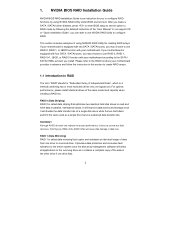
... surviving drive as a single drive but at a sustained data transfer rate. If your motherboard is equipped with two SATA / SATAII ports, you may choose to use RAID 0, RAID 1, or JBOD function with your...", you to read and write data in parallel, interleaved stacks. If your motherboard provides in advance and follow the instruction in the other drive if one drive to the RAID functions your... motherboard is equipped with four SATA / SATAII ports, you install. Please refer to a second drive...
... surviving drive as a single drive but at a sustained data transfer rate. If your motherboard is equipped with two SATA / SATAII ports, you may choose to use RAID 0, RAID 1, or JBOD function with your...", you to read and write data in parallel, interleaved stacks. If your motherboard provides in advance and follow the instruction in the other drive if one drive to the RAID functions your... motherboard is equipped with four SATA / SATAII ports, you install. Please refer to a second drive...
RAID Installation Guide
Page 5
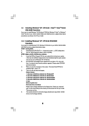
...format the floppy diskette and copy SATA / SATAII drivers into your optical drive to boot your system. (There are two ASRock Support CD in the motherboard gift box pack, please choose the one for WindowsXP64 4. Exit Reboot system now Press any key. Select your SATA /... CD-ROM as the boot device. D. Then press any key to continue Please insert a floppy diskette into the floppy drive. A. Insert the ASRock Support CD into the floppy diskette. 5 Then you install. E. Generate AHCI Driver diskette for WindowsXP 3. Generate AHCI Driver diskette for Windows®...
...format the floppy diskette and copy SATA / SATAII drivers into your optical drive to boot your system. (There are two ASRock Support CD in the motherboard gift box pack, please choose the one for WindowsXP64 4. Exit Reboot system now Press any key. Select your SATA /... CD-ROM as the boot device. D. Then press any key to continue Please insert a floppy diskette into the floppy drive. A. Insert the ASRock Support CD into the floppy diskette. 5 Then you install. E. Generate AHCI Driver diskette for WindowsXP 3. Generate AHCI Driver diskette for Windows®...
RAID Installation Guide
Page 7
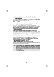
... CD into the optical drive to boot your system, and follow below steps. NVIDIA® RAID drivers are two ASRock Support CD in the motherboard gift box pack, please choose the one for proper configuration. 1.3.2 Installing Windows® VistaTM / VistaTM 64-bit With RAID Functions If you want to install ...
... CD into the optical drive to boot your system, and follow below steps. NVIDIA® RAID drivers are two ASRock Support CD in the motherboard gift box pack, please choose the one for proper configuration. 1.3.2 Installing Windows® VistaTM / VistaTM 64-bit With RAID Functions If you want to install ...

RAID Installation Guide
Page 12
... second port In this section, we take RAID 0 for example to show you plan to use NVRAIDMAN to the RAID functions your motherboard is equipped with your motherboard. Please refer to create other RAID arrays, 12 Please refer to create RAID arrays. If you how to create RAID 0 (Striping... use NVRAIDMAN to use RAID 0, RAID 1, or JBOD function with two SATA / SATAII ports, you install. RAID 0: Striping - If your motherboard is different from NVIDIA utility naming. Creating RAID Arrays This section includes examples of using NVRAIDMAN for detailed information. If your...
... second port In this section, we take RAID 0 for example to show you plan to use NVRAIDMAN to the RAID functions your motherboard is equipped with your motherboard. Please refer to create other RAID arrays, 12 Please refer to create RAID arrays. If you how to create RAID 0 (Striping... use NVRAIDMAN to use RAID 0, RAID 1, or JBOD function with two SATA / SATAII ports, you install. RAID 0: Striping - If your motherboard is different from NVIDIA utility naming. Creating RAID Arrays This section includes examples of using NVRAIDMAN for detailed information. If your...

User Manual
Page 2
..., transcribed, transmitted, or translated in any language, in any form or by any means, except duplication of documentation by ASRock. When you discard the Lithium battery in California, USA, please follow the related regulations in Perchlorate Best Management Practices (BMP...manual, ASRock does not provide warranty of ASRock Inc. "Perchlorate Material-special handling may not be constructed as a commitment by the purchaser for identification or explanation and to the contents of the FCC Rules. Products and corporate names appearing in this motherboard contains Perchlorate...
..., transcribed, transmitted, or translated in any language, in any form or by any means, except duplication of documentation by ASRock. When you discard the Lithium battery in California, USA, please follow the related regulations in Perchlorate Best Management Practices (BMP...manual, ASRock does not provide warranty of ASRock Inc. "Perchlorate Material-special handling may not be constructed as a commitment by the purchaser for identification or explanation and to the contents of the FCC Rules. Products and corporate names appearing in this motherboard contains Perchlorate...

User Manual
Page 3
Contents 1 Introduction 5 1.1 Package Contents 5 1.2 Specifications 6 1.3 Motherboard Layout (N73PV-S 9 1.4 Motherboard Layout (N73V-S 10 1.5 I/O Panel 11 2 Installation 12 2.1 Screw Holes 12 2.2 Pre-installation Precautions 12 2.3 CPU Installation 13 2.4 Installation of Heatsink and CPU fan 15 2.5 Installation of Memory ...
Contents 1 Introduction 5 1.1 Package Contents 5 1.2 Specifications 6 1.3 Motherboard Layout (N73PV-S 9 1.4 Motherboard Layout (N73V-S 10 1.5 I/O Panel 11 2 Installation 12 2.1 Screw Holes 12 2.2 Pre-installation Precautions 12 2.3 CPU Installation 13 2.4 Installation of Heatsink and CPU fan 15 2.5 Installation of Memory ...

User Manual
Page 5
... subject to change without further notice. Chapter 1 Introduction Thank you for specific information about the model you require technical support related to this motherboard, please visit our website for purchasing ASRock N73PV-S / N73V-S motherboard, a reliable motherboard produced under ASRock's consistently stringent quality control. Chapter 3 and 4 contain the configuration guide to BIOS setup and information of the...
... subject to change without further notice. Chapter 1 Introduction Thank you for specific information about the model you require technical support related to this motherboard, please visit our website for purchasing ASRock N73PV-S / N73V-S motherboard, a reliable motherboard produced under ASRock's consistently stringent quality control. Chapter 3 and 4 contain the configuration guide to BIOS setup and information of the...

User Manual
Page 8
...Threading Technology", please check page 39. 2. While CPU overheat is a user-friendly ASRock overclocking tool which allows you resume the system, please check if the CPU fan on the motherboard functions properly and unplug the power cord, then plug it is subject to get...SATAII connector, please read "Untied Overclocking Technology" on page 24 to adjust your hardware devices to change. This motherboard supports Untied Overclocking Technology. ASRock website: http://www.asrock.com 8. Please read the "SATAII Hard Disk Setup Guide" on page 32 for system usage under Microsoft&#...
...Threading Technology", please check page 39. 2. While CPU overheat is a user-friendly ASRock overclocking tool which allows you resume the system, please check if the CPU fan on the motherboard functions properly and unplug the power cord, then plug it is subject to get...SATAII connector, please read "Untied Overclocking Technology" on page 24 to adjust your hardware devices to change. This motherboard supports Untied Overclocking Technology. ASRock website: http://www.asrock.com 8. Please read the "SATAII Hard Disk Setup Guide" on page 32 for system usage under Microsoft&#...

User Manual
Page 9
...; Yellow) (HD_AUDIO1, Lime) 6 ATX Power Connector (ATXPWR1) 19 Internal Audio Connector: CD1 (Black) 7 IDE1 Connector (IDE1, Blue) 20 PCI Slots (PCI1- 2) 8 Primary SATAII Connector (SATAII_1; 1.3 Motherboard Layout (N73PV-S) PS2 Mouse PS2 Keyboard 1 2 34 5 17.8cm (7.0 in) 1 PS2_USB_PWR1 CPU_FAN1 6 COM1 ATXPWR1 24.4cm (9.6 in) DDRII_2 (64 bit, 240-pin module) DDRII_1 (64...
...; Yellow) (HD_AUDIO1, Lime) 6 ATX Power Connector (ATXPWR1) 19 Internal Audio Connector: CD1 (Black) 7 IDE1 Connector (IDE1, Blue) 20 PCI Slots (PCI1- 2) 8 Primary SATAII Connector (SATAII_1; 1.3 Motherboard Layout (N73PV-S) PS2 Mouse PS2 Keyboard 1 2 34 5 17.8cm (7.0 in) 1 PS2_USB_PWR1 CPU_FAN1 6 COM1 ATXPWR1 24.4cm (9.6 in) DDRII_2 (64 bit, 240-pin module) DDRII_1 (64...

User Manual
Page 10
... Connector (ATX12V1) 14 System Panel Header (PANEL1, Orange) 10 Red) 24 USB 2.0 Header (USB6_7, Blue) 12 Fourth SATAII Connector (SATAII_4; 1.4 Motherboard Layout (N73V-S) PS2 Mouse PS2 Keyboard 1 2 34 5 17.8cm (7.0 in) 1 PS2_USB_PWR1 CPU_FAN1 6 COM1 ATXPWR1 24.4cm (9.6 in) DDRII_2 (64 bit, 240...USB1 Top: RJ-45 Top: LINE IN Center: FRONT Bottom: MIC IN LAN PHY USB4_5 USB6_7 NVIDIA GeForce 7050 / nForce 610i Chipset N73V-S RoHS PCIE1 4Mb BIOS CMOS Battery Super I/O CD1 AUDIO CODEC HD_AUDIO1 1 FLOPPY1 17 PCIE2 PCI1 PCI2 LPT1 1 16 RAID SATAII_1 SATAII_3 ...
... Connector (ATX12V1) 14 System Panel Header (PANEL1, Orange) 10 Red) 24 USB 2.0 Header (USB6_7, Blue) 12 Fourth SATAII Connector (SATAII_4; 1.4 Motherboard Layout (N73V-S) PS2 Mouse PS2 Keyboard 1 2 34 5 17.8cm (7.0 in) 1 PS2_USB_PWR1 CPU_FAN1 6 COM1 ATXPWR1 24.4cm (9.6 in) DDRII_2 (64 bit, 240...USB1 Top: RJ-45 Top: LINE IN Center: FRONT Bottom: MIC IN LAN PHY USB4_5 USB6_7 NVIDIA GeForce 7050 / nForce 610i Chipset N73V-S RoHS PCIE1 4Mb BIOS CMOS Battery Super I/O CD1 AUDIO CODEC HD_AUDIO1 1 FLOPPY1 17 PCIE2 PCI1 PCI2 LPT1 1 16 RAID SATAII_1 SATAII_3 ...

User Manual
Page 12
...so may cause physical injuries to you and damages to motherboard components. 2.1 Screw Holes Place screws into it on the carpet or the like. Chapter 2 Installation N73PV-S / N73V-S is detached from the wall socket before you install motherboard components or change any component. 2. Make sure to... ensure that the motherboard fits into the holes indicated by the edges and do so may cause severe...
...so may cause physical injuries to you and damages to motherboard components. 2.1 Screw Holes Place screws into it on the carpet or the like. Chapter 2 Installation N73PV-S / N73V-S is detached from the wall socket before you install motherboard components or change any component. 2. Make sure to... ensure that the motherboard fits into the holes indicated by the edges and do so may cause severe...

User Manual
Page 14
... thumb and peel the cap from the socket while pressing on load plate, engage the load lever. This cap must be placed if returning the motherboard for after service. Step 2-3. Rotate the load plate onto the IHS. Step 4-2. Carefully place the CPU into the socket by using a purely vertical motion. It...
... thumb and peel the cap from the socket while pressing on load plate, engage the load lever. This cap must be placed if returning the motherboard for after service. Step 2-3. Rotate the load plate onto the IHS. Step 4-2. Carefully place the CPU into the socket by using a purely vertical motion. It...

User Manual
Page 15
...-Pin socket that the CPU and the heatsink are oriented on side closest to the CPU fan connector on the motherboard. Step 5. 2.4 Installation of CPU Fan and Heatsink This motherboard is an example to illustrate the installation of IHS on the socket surface. Before you installed the heatsink, you ...press down on the motherboard. Then connect the CPU fan to the CPU_FAN connector (CPU_FAN1, see page 9/10, No. 4). Apply thermal interface material onto center of the ...
...-Pin socket that the CPU and the heatsink are oriented on side closest to the CPU fan connector on the motherboard. Step 5. 2.4 Installation of CPU Fan and Heatsink This motherboard is an example to illustrate the installation of IHS on the socket surface. Before you installed the heatsink, you ...press down on the motherboard. Then connect the CPU fan to the CPU_FAN connector (CPU_FAN1, see page 9/10, No. 4). Apply thermal interface material onto center of the ...

User Manual
Page 16
It will cause permanent damage to disconnect power supply before adding or removing DIMMs or the system components. 2.5 Installation of Memory Modules (DIMM) This motherboard provides two 240-pin DDR2 (Double Data Rate 2) DIMM slots. Step 1. notch break notch break The DIMM only fits in place and the DIMM is ... outward. Align a DIMM on the slot such that the notch on the DIMM matches the break on the slot. Step 3. Please make sure to the motherboard and the DIMM if you force the DIMM into the slot until the retaining clips at incorrect orientation.
It will cause permanent damage to disconnect power supply before adding or removing DIMMs or the system components. 2.5 Installation of Memory Modules (DIMM) This motherboard provides two 240-pin DDR2 (Double Data Rate 2) DIMM slots. Step 1. notch break notch break The DIMM only fits in place and the DIMM is ... outward. Align a DIMM on the slot such that the notch on the DIMM matches the break on the slot. Step 3. Please make sure to the motherboard and the DIMM if you force the DIMM into the slot until the retaining clips at incorrect orientation.

User Manual
Page 17
... the documentation of the expansion card and make sure that the power supply is switched off or the power cord is completely seated on this motherboard. PCI slots: PCI slots are 2 PCI slots and 2 PCI Express slots on the slot. Before installing the expansion card, please make necessary hardware settings for...
... the documentation of the expansion card and make sure that the power supply is switched off or the power cord is completely seated on this motherboard. PCI slots: PCI slots are 2 PCI slots and 2 PCI Express slots on the slot. Before installing the expansion card, please make necessary hardware settings for...

User Manual
Page 18
...when the add-on VGA card is inserted to the VGA/DVI-D connector of onboard VGA/D-sub. Connect the DVI-D monitor cable to this motherboard. 4. Please make sure that you have installed the onboard VGA driver already, there is less than the total capability of the system memory.... 1. Please refer to the following steps to install it again. 5. Click the "Identify" button to enter BIOS setup. C. 2.7 Easy Multi Monitor Feature This motherboard supports Multi Monitor upgrade. For Windows® XP / XP 64-bit OS: Right click the desktop, choose "Properties", and select the "Settings" tab so ...
...when the add-on VGA card is inserted to the VGA/DVI-D connector of onboard VGA/D-sub. Connect the DVI-D monitor cable to this motherboard. 4. Please make sure that you have installed the onboard VGA driver already, there is less than the total capability of the system memory.... 1. Please refer to the following steps to install it again. 5. Click the "Identify" button to enter BIOS setup. C. 2.7 Easy Multi Monitor Feature This motherboard supports Multi Monitor upgrade. For Windows® XP / XP 64-bit OS: Right click the desktop, choose "Properties", and select the "Settings" tab so ...

User Manual
Page 20
...data transfer rate. Primary IDE connector (Blue) (39-pin IDE1, see p.9/10 No. 7) PIN1 IDE1 connect the blue end to the motherboard connect the black end to the IDE devices 80-conductor ATA 66/100133 cable Note: Please refer to the power connector of your IDE device...connector on each drive. Serial ATA (SATA) Power Cable (Optional) connect to the SATA HDD power connector connect to the power connector on this motherboard. FDD connector (33-pin FLOPPY1) (see p.9/10, No. 12) SATAII_1 SATAII_3 SATAII_2 SATAII_4 These four Serial ATAII (SATAII) connectors support SATA...
...data transfer rate. Primary IDE connector (Blue) (39-pin IDE1, see p.9/10 No. 7) PIN1 IDE1 connect the blue end to the motherboard connect the black end to the IDE devices 80-conductor ATA 66/100133 cable Note: Please refer to the power connector of your IDE device...connector on each drive. Serial ATA (SATA) Power Cable (Optional) connect to the SATA HDD power connector connect to the power connector on this motherboard. FDD connector (33-pin FLOPPY1) (see p.9/10, No. 12) SATAII_1 SATAII_3 SATAII_2 SATAII_4 These four Serial ATAII (SATAII) connectors support SATA...

User Manual
Page 21
...GND P+6 P-6 USB_PWR USB_PWR P-9 P+9 GND DUMMY 1 GND P+8 P-8 USB_PWR Besides four default USB 2.0 ports on the I /O panel, there are three USB 2.0 headers on this motherboard. USB_PWR P-5 P+5 GND DUMMY 1 GND P+4 P-4 USB_PWR USB_PWR P-7 P+7 GND DUMMY 1 GND P+6 P-6 USB_PWR Besides four default USB 2.0 ports on the I /O panel, there .... N73PV-S: USB 2.0 Headers (9-pin US4_5) (see p.9 No. 26) (9-pin USB6_7) (see p.9 No. 25) (9-pin USB8_9) (see p.9 No. 24) N73V-S: USB 2.0 Headers (9-pin US4_5) (see p.10 No. 25) (9-pin USB6_7) (see p.9/10 No. 16) AFD# ERROR# PINIT# SLIN# GND 1 SPD7 SPD6...
...GND P+6 P-6 USB_PWR USB_PWR P-9 P+9 GND DUMMY 1 GND P+8 P-8 USB_PWR Besides four default USB 2.0 ports on the I /O panel, there are three USB 2.0 headers on this motherboard. USB_PWR P-5 P+5 GND DUMMY 1 GND P+4 P-4 USB_PWR USB_PWR P-7 P+7 GND DUMMY 1 GND P+6 P-6 USB_PWR Besides four default USB 2.0 ports on the I /O panel, there .... N73PV-S: USB 2.0 Headers (9-pin US4_5) (see p.9 No. 26) (9-pin USB6_7) (see p.9 No. 25) (9-pin USB8_9) (see p.9 No. 24) N73V-S: USB 2.0 Headers (9-pin US4_5) (see p.10 No. 25) (9-pin USB6_7) (see p.9/10 No. 16) AFD# ERROR# PINIT# SLIN# GND 1 SPD7 SPD6...

User Manual
Page 23
... speaker to this connector. 23 ATX 12V Connector (4-pin ATX12V1) (see p.9/10 No. 4) 1 GND Please connect a CPU fan cable 2 +12V 3 CPU_FAN_SPEED to this motherboard provides 24-pin ATX power connector, 12 24 it can work if you plan to connect the 3-Pin CPU fan to the CPU fan connector... connect it to this connector. 1 13 Though this connector and match 4 FAN_SPEED_CONTROL the black wire to the ground pin. Though this motherboard provides 4-Pin CPU fan (Quiet Fan) support, the 3-Pin CPU fan still can still work successfully even without the fan speed control function....
... speaker to this connector. 23 ATX 12V Connector (4-pin ATX12V1) (see p.9/10 No. 4) 1 GND Please connect a CPU fan cable 2 +12V 3 CPU_FAN_SPEED to this motherboard provides 24-pin ATX power connector, 12 24 it can work if you plan to connect the 3-Pin CPU fan to the CPU fan connector... connect it to this connector. 1 13 Though this connector and match 4 FAN_SPEED_CONTROL the black wire to the ground pin. Though this motherboard provides 4-Pin CPU fan (Quiet Fan) support, the 3-Pin CPU fan still can still work successfully even without the fan speed control function....

User Manual
Page 25
...then it is called "Hot Plug" for the action to insert and remove the SATA / SATAII HDDs while the system is still power-on this motherboard for the action to insert and remove the SATA / SATAII HDDs while the system is still power-on and in RAID / AHCI mode. If ... note that supports Serial ATA (SATA) / Serial ATAII (SATAII) hard disks and RAID functions. 2 . 1 1 Serial ATA (SATA) / Serial ATAII (SATAII) Hard Disks Installation This motherboard adopts NVIDIA® chipset that it cannot perform Hot Plug if the OS has been installed into the drive bays of your chassis. This section...
...then it is called "Hot Plug" for the action to insert and remove the SATA / SATAII HDDs while the system is still power-on this motherboard for the action to insert and remove the SATA / SATAII HDDs while the system is still power-on and in RAID / AHCI mode. If ... note that supports Serial ATA (SATA) / Serial ATAII (SATAII) hard disks and RAID functions. 2 . 1 1 Serial ATA (SATA) / Serial ATAII (SATAII) Hard Disks Installation This motherboard adopts NVIDIA® chipset that it cannot perform Hot Plug if the OS has been installed into the drive bays of your chassis. This section...

