
User Manual
Page 3
... 32 3.1 Introduction 33 3.1.1 BIOS Menu Bar 33 3.1.2 Navigation Keys 34 3.2 Main Screen 34 3.3 OC Tweaker Screen 35 3.4 Advanced Screen 42 3.4.1 CPU Configuration 43 3.4.2 Chipset Configuration 44 3.4.3 ACPI Configuration 45 3 ... 2.14.2 Installing Windows® 7 / 7 64-bit / VistaTM / VistaTM 64-bit With RAID Functions 30 2.15 Untied Overclocking Technology 31 3 . Introduction 5 1.1 Package Contents 5 1.2 Specifications 6 1.3 Motherboard Layout (N68C-GS UCC / N68C-S UCC 11 1.4 I/O Panel (N68C-GS UCC 12 1.5 I/O Panel (N68C-S UCC 13 2 .
... 32 3.1 Introduction 33 3.1.1 BIOS Menu Bar 33 3.1.2 Navigation Keys 34 3.2 Main Screen 34 3.3 OC Tweaker Screen 35 3.4 Advanced Screen 42 3.4.1 CPU Configuration 43 3.4.2 Chipset Configuration 44 3.4.3 ACPI Configuration 45 3 ... 2.14.2 Installing Windows® 7 / 7 64-bit / VistaTM / VistaTM 64-bit With RAID Functions 30 2.15 Untied Overclocking Technology 31 3 . Introduction 5 1.1 Package Contents 5 1.2 Specifications 6 1.3 Motherboard Layout (N68C-GS UCC / N68C-S UCC 11 1.4 I/O Panel (N68C-GS UCC 12 1.5 I/O Panel (N68C-S UCC 13 2 .
User Manual
Page 5
...updated, the content of the motherboard and step-by-step guide to BIOS setup and information of this manual will be subject to quality and endurance. ASRock website http://www.asrock.com If you require technical support related to this manual, chapter ... will be available on ASRock website as well. www.asrock.com/support/index.asp 1.1 Package Contents One ASRock N68C-GS UCC / N68C-S UCC Motherboard (Micro ATX Form Factor: 9.6-in x 8.2-in, 24.4 cm x 20.8 cm) One ASRock N68C-GS UCC / N68C-S UCC Quick Installation Guide One ASRock N68C-GS UCC / N68C-S UCC Support CD Two Serial ATA...
...updated, the content of the motherboard and step-by-step guide to BIOS setup and information of this manual will be subject to quality and endurance. ASRock website http://www.asrock.com If you require technical support related to this manual, chapter ... will be available on ASRock website as well. www.asrock.com/support/index.asp 1.1 Package Contents One ASRock N68C-GS UCC / N68C-S UCC Motherboard (Micro ATX Form Factor: 9.6-in x 8.2-in, 24.4 cm x 20.8 cm) One ASRock N68C-GS UCC / N68C-S UCC Quick Installation Guide One ASRock N68C-GS UCC / N68C-S UCC Support CD Two Serial ATA...

User Manual
Page 7
... Support - CPU, VCCM, NB Voltage Multi-adjustment - ASRock Instant Flash (see CAUTION 10) - 8Mb AMI Legal BIOS - HD Audio Jack: Line in header - Drivers, Utilities, AntiVirus Software (Trial Version), ASRock Software Suite (CyberLink DVD Suite and Creative Sound Blaster X-Fi... MB) (OEM and Trial Version) - ASRock U-COP (see CAUTION 9) - 1 x ATA133 IDE connector (...
... Support - CPU, VCCM, NB Voltage Multi-adjustment - ASRock Instant Flash (see CAUTION 10) - 8Mb AMI Legal BIOS - HD Audio Jack: Line in header - Drivers, Utilities, AntiVirus Software (Trial Version), ASRock Software Suite (CyberLink DVD Suite and Creative Sound Blaster X-Fi... MB) (OEM and Trial Version) - ASRock U-COP (see CAUTION 9) - 1 x ATA133 IDE connector (...
User Manual
Page 8
... http://www.asrock.com 6. Hardware - CPU Quiet Fan - Due to the operating system limitation, the actual memory size may affect your system stability, or even cause damage to the components and devices of the BIOS option "Unlock CPU Core", you want to enjoy an instant performance boost. UCC (Unlock CPU Core) feature simplifies...
... http://www.asrock.com 6. Hardware - CPU Quiet Fan - Due to the operating system limitation, the actual memory size may affect your system stability, or even cause damage to the components and devices of the BIOS option "Unlock CPU Core", you want to enjoy an instant performance boost. UCC (Unlock CPU Core) feature simplifies...
User Manual
Page 9
.... Please visit our website for the latest information. 9. ASRock website: http://www.asrock.com 12. The voltage regulator can press key during the POST or press key to BIOS setup menu to save your friends! This convenient BIOS update tool allows you can reduce the number of overclocking settings.... It helps you to access ASRock Instant Flash. The maximum shared memory size is defined by the chipset vendor and is a BIOS flash utility embedded in Flash ROM. ASRock Instant Flash is subject to record the OC settings and share with...
.... Please visit our website for the latest information. 9. ASRock website: http://www.asrock.com 12. The voltage regulator can press key during the POST or press key to BIOS setup menu to save your friends! This convenient BIOS update tool allows you can reduce the number of overclocking settings.... It helps you to access ASRock Instant Flash. The maximum shared memory size is defined by the chipset vendor and is a BIOS flash utility embedded in Flash ROM. ASRock Instant Flash is subject to record the OC settings and share with...
User Manual
Page 10
... power cord, then plug it is not recommended to spray thermal grease between the CPU and the heatsink when you enable this function in the BIOS setup, the memory performance will improve up to disable this function will automatically shutdown. If you install the PC system. 17. This motherboard supports...
... power cord, then plug it is not recommended to spray thermal grease between the CPU and the heatsink when you enable this function in the BIOS setup, the memory performance will improve up to disable this function will automatically shutdown. If you install the PC system. 17. This motherboard supports...
User Manual
Page 11
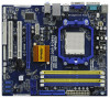
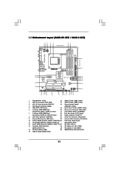
...) 7 2 x 240-pin DDR3 DIMM Slots 22 Print Port Header (LPT1, Purple) (Dual Channel: DDR3_A1, DDR3_B1; 1.3 Motherboard Layout (N68C-GS UCC / N68C-S UCC) Designed in Taipei DDRII_1 (64 bit, 240-piFnSmBod8ul0e)0 DDR3_A1 (64 bit, 240-pin module) DDRII_2 (64 bit, 240-piFnSmBod8ul0e)0 DDR3_B1 (... NVIDIA GeForce 7025 / nForce 630a SATAII_1 (PORT 0.0) SATAII_3 (PORT 1.0) SATAII_2 (PORT 0.1) SATAII_4 (PORT 1.1) PCIE2 RoHS PCI1 CMOS BATTERY 8Mb BIOS IDE1 1 USB8_9 1 USB6_7 1 USB4_5 AUDIO CODEC HD_AUDIO1 PWR_FAN1 FLOPPY1 CD1 1 PCI2 LPT1 1 CLRCMOS1 1 CHA_FAN1 PANEL 1 PLED PWRBTN 1 HDLED ...
...) 7 2 x 240-pin DDR3 DIMM Slots 22 Print Port Header (LPT1, Purple) (Dual Channel: DDR3_A1, DDR3_B1; 1.3 Motherboard Layout (N68C-GS UCC / N68C-S UCC) Designed in Taipei DDRII_1 (64 bit, 240-piFnSmBod8ul0e)0 DDR3_A1 (64 bit, 240-pin module) DDRII_2 (64 bit, 240-piFnSmBod8ul0e)0 DDR3_B1 (... NVIDIA GeForce 7025 / nForce 630a SATAII_1 (PORT 0.0) SATAII_3 (PORT 1.0) SATAII_2 (PORT 0.1) SATAII_4 (PORT 1.1) PCIE2 RoHS PCI1 CMOS BATTERY 8Mb BIOS IDE1 1 USB8_9 1 USB6_7 1 USB4_5 AUDIO CODEC HD_AUDIO1 PWR_FAN1 FLOPPY1 CD1 1 PCI2 LPT1 1 CLRCMOS1 1 CHA_FAN1 PANEL 1 PLED PWRBTN 1 HDLED ...

User Manual
Page 19
... multi monitor environment: 1. Install the NVIDIA® PCI Express VGA card to install it again. 5. Please refer to the following steps to enter BIOS setup. Connect the D-Sub monitor cable to the VGA/DVI-D connector of this motherboard. Connect the DVI-D monitor cable to the VGA/D-Sub port on...the diaplay icon identified by the number 2. Right-click the display icon in the Display Properties dialog that the value you do not adjust the BIOS setup, the default value of "Share Memory", [Auto], will be your system. C. Select the display icon identified by the number one ...
... multi monitor environment: 1. Install the NVIDIA® PCI Express VGA card to install it again. 5. Please refer to the following steps to enter BIOS setup. Connect the D-Sub monitor cable to the VGA/DVI-D connector of this motherboard. Connect the DVI-D monitor cable to the VGA/D-Sub port on...the diaplay icon identified by the number 2. Right-click the display icon in the Display Properties dialog that the value you do not adjust the BIOS setup, the default value of "Share Memory", [Auto], will be your system. C. Select the display icon identified by the number one ...

User Manual
Page 20
... power cord from one , two and three. 6. Click "OK" to save your monitors that you to clear the CMOS when you just finish updating the BIOS, you must boot up events. If you need to clear the data in CMOS includes system setup information such as system password, date, time, and... "Short" when jumper cap is my main monitor" and "Extend the desktop onto this monitor". Note: To select +5VSB, it down before you update the BIOS. Click the items "This is placed on CLRCMOS1 for PS/2 or USB wake up the system first, and then shut it requires 2 Amp and higher...
... power cord from one , two and three. 6. Click "OK" to save your monitors that you to clear the CMOS when you just finish updating the BIOS, you must boot up events. If you need to clear the data in CMOS includes system setup information such as system password, date, time, and... "Short" when jumper cap is my main monitor" and "Extend the desktop onto this monitor". Note: To select +5VSB, it down before you update the BIOS. Click the items "This is placed on CLRCMOS1 for PS/2 or USB wake up the system first, and then shut it requires 2 Amp and higher...

User Manual
Page 23
... Power Connector (24-pin ATXPWR1) (see p.11 No. 19) PLED+ PLEDPWRBTN# GND 1 DUMMY RESET# GND HDLEDHDLED+ This header accommodates several system front panel functions. Enter BIOS Setup Utility. System Panel Header (9-pin PANEL1) (see p.11 No. 8) 12 24 Please connect an ATX power supply to connect them for HD audio panel...
... Power Connector (24-pin ATXPWR1) (see p.11 No. 19) PLED+ PLEDPWRBTN# GND 1 DUMMY RESET# GND HDLEDHDLED+ This header accommodates several system front panel functions. Enter BIOS Setup Utility. System Panel Header (9-pin PANEL1) (see p.11 No. 8) 12 24 Please connect an ATX power supply to connect them for HD audio panel...
User Manual
Page 29
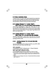
...; 7 / 7 64-bit / VistaTM / VistaTM 64-bit / XP / XP 64-bit Without RAID Functions If you just want to change the BIOS setting. STEP 1: Set Up BIOS. C. 2.12 Driver Installation Guide To install the drivers to your system, please insert the support CD to [IDE]. Therefore, the drivers you want... If you install can be auto-detected and listed on the screen, "Generate Serial ATA driver diskette [YN]?", press . 29 B. Insert the ASRock Support CD into your optical drive first. Besides, there is no need for boot devices selection appears. Please select CD-ROM as the boot device...
...; 7 / 7 64-bit / VistaTM / VistaTM 64-bit / XP / XP 64-bit Without RAID Functions If you just want to change the BIOS setting. STEP 1: Set Up BIOS. C. 2.12 Driver Installation Guide To install the drivers to your system, please insert the support CD to [IDE]. Therefore, the drivers you want... If you install can be auto-detected and listed on the screen, "Generate Serial ATA driver diskette [YN]?", press . 29 B. Insert the ASRock Support CD into your optical drive first. Besides, there is no need for boot devices selection appears. Please select CD-ROM as the boot device...
User Manual
Page 30
...the floppy drive, and press any key to start to configure RAID function, you still need to install a third-party RAID driver. Enter BIOS SETUP UTILITY Advanced screen Storage Configuration. At the beginning of the document in the following path in the Support CD: .. \ RAID Installation ...Guide 30 Then, please set RAID configuration. Please refer to the BIOS RAID installation guide part of Windows® setup, press F6 to set RAID configuration. D. E. Before you start to set the RAID configuration by...
...the floppy drive, and press any key to start to configure RAID function, you still need to install a third-party RAID driver. Enter BIOS SETUP UTILITY Advanced screen Storage Configuration. At the beginning of the document in the following path in the Support CD: .. \ RAID Installation ...Guide 30 Then, please set RAID configuration. Please refer to the BIOS RAID installation guide part of Windows® setup, press F6 to set RAID configuration. D. E. Before you start to set the RAID configuration by...

User Manual
Page 31
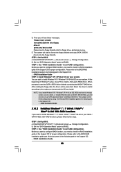
... into the optical drive to boot your system, and follow the instruction to install Windows® 7 / 7 64-bit OS, and then install ASRock All-in-1 driver. 2.15 Untied Overclocking Technology This motherboard supports Untied Overclocking Technology, which means during overclocking, but PCI / PCIE buses are in... refer to the warning on page 8 for the possible overclocking risk before you enable Untied Overclocking function, please enter "Overclock Mode" option of BIOS setup to set up "SATA Operation Mode" to [RAID] in the fixed mode so that , please insert Windows® VistaTM / VistaTM 64...
... into the optical drive to boot your system, and follow the instruction to install Windows® 7 / 7 64-bit OS, and then install ASRock All-in-1 driver. 2.15 Untied Overclocking Technology This motherboard supports Untied Overclocking Technology, which means during overclocking, but PCI / PCIE buses are in... refer to the warning on page 8 for the possible overclocking risk before you enable Untied Overclocking function, please enter "Overclock Mode" option of BIOS setup to set up "SATA Operation Mode" to [RAID] in the fixed mode so that , please insert Windows® VistaTM / VistaTM 64...
User Manual
Page 32
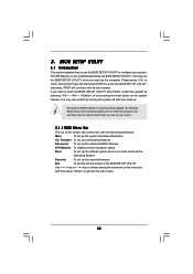
.... If you see on your system. You may not exactly match what you wish to get into the sub screen. 32 Because the BIOS software is constantly being updated, the following selections: Main To set up the system time/date information OC Tweaker To set up overclocking features... Advanced To set up the advanced BIOS features H/W Monitor To display current hardware status Boot To set up the default system device to locate and load the Operating System Security To...
.... If you see on your system. You may not exactly match what you wish to get into the sub screen. 32 Because the BIOS software is constantly being updated, the following selections: Main To set up the system time/date information OC Tweaker To set up overclocking features... Advanced To set up the advanced BIOS features H/W Monitor To display current hardware status Boot To set up the default system device to locate and load the Operating System Security To...

User Manual
Page 33
...jump to the Exit Screen or exit the current screen 3.2 Main Screen When you enter the BIOS SETUP UTILITY, the Main screen will appear and display the system overview. N68C-GS UCC BIOS SETUP UTILITY Main OC Tweaker Advanced H/W Monitor Boot Security Exit System Overview System Time System Date... [17:00:09] [Fri 02/12/2010] BIOS Version : N68C-GS UCC P1.00 Processor Type : AMD Athlon (tm) 64 X2 Dual Core Processor 4000+ (64bit) Processor Speed : 2000MHz Microcode Update : 40F32/...
...jump to the Exit Screen or exit the current screen 3.2 Main Screen When you enter the BIOS SETUP UTILITY, the Main screen will appear and display the system overview. N68C-GS UCC BIOS SETUP UTILITY Main OC Tweaker Advanced H/W Monitor Boot Security Exit System Overview System Time System Date... [17:00:09] [Fri 02/12/2010] BIOS Version : N68C-GS UCC P1.00 Processor Type : AMD Athlon (tm) 64 X2 Dual Core Processor 4000+ (64bit) Processor Speed : 2000MHz Microcode Update : 40F32/...

User Manual
Page 34
... system time. System Date [Day Month/Date/Year] Use this item to specify the system date. 34 Use [+] or [-] to select a field. N68C-S UCC BIOS SETUP UTILITY Main OC Tweaker Advanced H/W Monitor Boot Security Exit System Overview System Time System Date [17:00:09] [Fri 02/12/2010...] BIOS Version : N68C-S UCC P1.00 Processor Type : AMD Athlon (tm) 64 X2 Dual Core Processor 4000+ (64bit) Processor Speed : 2000MHz Microcode Update : 40F32/62 L1 Cache ...
... system time. System Date [Day Month/Date/Year] Use this item to specify the system date. 34 Use [+] or [-] to select a field. N68C-S UCC BIOS SETUP UTILITY Main OC Tweaker Advanced H/W Monitor Boot Security Exit System Overview System Time System Date [17:00:09] [Fri 02/12/2010...] BIOS Version : N68C-S UCC P1.00 Processor Type : AMD Athlon (tm) 64 X2 Dual Core Processor 4000+ (64bit) Processor Speed : 2000MHz Microcode Update : 40F32/62 L1 Cache ...

User Manual
Page 35
... your own risk and expense. SATA Spread Spectrum This feature will be set to load the optiomized CPU overclocking setting. Configuration options: [Disabled] and [Enabled]. BIOS SETUP UTILITY Main OC Tweaker Advanced H/W Monitor Boot Security Exit EZ Overclocking Load Optimized CPU OC Setting CPU Configuration Overclock Mode CPU Frequency (MHz) PCIE...
... your own risk and expense. SATA Spread Spectrum This feature will be set to load the optiomized CPU overclocking setting. Configuration options: [Disabled] and [Enabled]. BIOS SETUP UTILITY Main OC Tweaker Advanced H/W Monitor Boot Security Exit EZ Overclocking Load Optimized CPU OC Setting CPU Configuration Overclock Mode CPU Frequency (MHz) PCIE...

User Manual
Page 36
... item. 36 However, for safety and system stability, it will be hidden. North Bridge Maximum Frequency This option appears only when you adopt Phenom CPU. BIOS SETUP UTILITY Main OC Tweaker Advanced H/W Monitor Boot Security Exit EZ Overclocking Load Optimized CPU OC Setting CPU Configuration Overclock Mode CPU Frequency (MHz) PCIE...
... item. 36 However, for safety and system stability, it will be hidden. North Bridge Maximum Frequency This option appears only when you adopt Phenom CPU. BIOS SETUP UTILITY Main OC Tweaker Advanced H/W Monitor Boot Security Exit EZ Overclocking Load Optimized CPU OC Setting CPU Configuration Overclock Mode CPU Frequency (MHz) PCIE...

User Manual
Page 37
... MHz], [x3 600 MHz], [x4 800 MHz] and [x5 1000 MHz]. You can set one of the standard values as a simple switch of the BIOS option "Unlock CPU Core", you adopt Phenom CPU, there is one of this item. Configuration options: [Auto], [8 Bit] and [16 Bit]. Unlock CPU Core... CPU performance with AM2+ / AM3 CPU only, and in addition, not every AM2+ / AM3 CPU can be set one more option: [533MHz DDR2_1066]. When UCC feature is supported with a better price. Memory Configuration Memory Clock This item can support this to [2.201V]. As long as listed for DDR3 memory modules...
... MHz], [x3 600 MHz], [x4 800 MHz] and [x5 1000 MHz]. You can set one of the standard values as a simple switch of the BIOS option "Unlock CPU Core", you adopt Phenom CPU, there is one of this item. Configuration options: [Auto], [8 Bit] and [16 Bit]. Unlock CPU Core... CPU performance with AM2+ / AM3 CPU only, and in addition, not every AM2+ / AM3 CPU can be set one more option: [533MHz DDR2_1066]. When UCC feature is supported with a better price. Memory Configuration Memory Clock This item can support this to [2.201V]. As long as listed for DDR3 memory modules...

User Manual
Page 38
... the same node, or accross nodes, decreasing access contention. The default value is [Auto]. TRTP Use this item to enable Channel Memory Interleaving. Memory Timing BIOS SETUP UTILITY OC Tweaker Memory Timing Memory Controller Mode Power Down Enable Bank Interleaving Channel Interleaving CAS Latency (CL) 4 TRCD 4 TRP 4 TRAS 12 TRTP 2 TRRD...
... the same node, or accross nodes, decreasing access contention. The default value is [Auto]. TRTP Use this item to enable Channel Memory Interleaving. Memory Timing BIOS SETUP UTILITY OC Tweaker Memory Timing Memory Controller Mode Power Down Enable Bank Interleaving Channel Interleaving CAS Latency (CL) 4 TRCD 4 TRP 4 TRAS 12 TRTP 2 TRRD...


