User Manual
Page 3
.... Introduction 5 1.1 Package Contents 5 1.2 Specifications 6 1.3 Motherboard Layout (N68C-GS FX / N68C-S FX 12 1.4 I/O Panel (N68C-GS FX 13 1.5 I/O Panel (N68C-S FX 14 2 . Installation 15 Pre-installation Precautions 15 2.1 CPU Installation 16 2.2 Installation of CPU Fan and Heatsink 16 2.3 Installation of Memory Modules (DIMM 17 2.4 Expansion Slots (PCI and PCI Express Slots... 22 2.8 SATAII Hard Disk Setup Guide 26 2.9 Serial ATA (SATA) / Serial ATAII (SATAII) Hard Disks Installation 27 2.10 Hot Plug and Hot Swap Functions for SATA / SATAII HDDs ....... 27 2.11 SATA / SATAII HDD...
.... Introduction 5 1.1 Package Contents 5 1.2 Specifications 6 1.3 Motherboard Layout (N68C-GS FX / N68C-S FX 12 1.4 I/O Panel (N68C-GS FX 13 1.5 I/O Panel (N68C-S FX 14 2 . Installation 15 Pre-installation Precautions 15 2.1 CPU Installation 16 2.2 Installation of CPU Fan and Heatsink 16 2.3 Installation of Memory Modules (DIMM 17 2.4 Expansion Slots (PCI and PCI Express Slots... 22 2.8 SATAII Hard Disk Setup Guide 26 2.9 Serial ATA (SATA) / Serial ATAII (SATAII) Hard Disks Installation 27 2.10 Hot Plug and Hot Swap Functions for SATA / SATAII HDDs ....... 27 2.11 SATA / SATAII HDD...
User Manual
Page 4
3.4.3 ACPI Configuration 43 3.4.4 Storage Configuration 44 3.4.5 PCIPnP Configuration 46 3.4.6 Floppy Configuration 47 3.4.7 Super IO Configuration 47 3.4.8 USB Configuration 49 3.5 Hardware Health Event Monitoring Screen 50 3.6 Boot Screen 51 3.6.1 Boot Settings Configuration 51 3.7 Security Screen 52 3.8 Exit Screen 53 4 . Software Support 54 4.1 Install Operating System 54 4.2 Support CD Information 54 4.2.1 Running Support CD 54 4.2.2 Drivers Menu 54 4.2.3 Utilities Menu 54 4.2.4 Contact Information 54 4
3.4.3 ACPI Configuration 43 3.4.4 Storage Configuration 44 3.4.5 PCIPnP Configuration 46 3.4.6 Floppy Configuration 47 3.4.7 Super IO Configuration 47 3.4.8 USB Configuration 49 3.5 Hardware Health Event Monitoring Screen 50 3.6 Boot Screen 51 3.6.1 Boot Settings Configuration 51 3.7 Security Screen 52 3.8 Exit Screen 53 4 . Software Support 54 4.1 Install Operating System 54 4.2 Support CD Information 54 4.2.1 Running Support CD 54 4.2.2 Drivers Menu 54 4.2.3 Utilities Menu 54 4.2.4 Contact Information 54 4
User Manual
Page 5
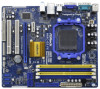
... will be subject to the hardware installation. You may find the latest VGA cards and CPU support lists on ASRock website without notice. www.asrock.com/support/index.asp 1.1 Package Contents One ASRock N68C-GS FX / N68C-S FX Motherboard (Micro ATX Form Factor: 9.6-in x 8.2-in, 24.4 cm x 20.8 cm) One ASRock N68C-GS FX / N68C-S FX Quick Installation Guide One ASRock N68C-GS FX / N68C-S FX Support CD Two Serial ATA (SATA...
... will be subject to the hardware installation. You may find the latest VGA cards and CPU support lists on ASRock website without notice. www.asrock.com/support/index.asp 1.1 Package Contents One ASRock N68C-GS FX / N68C-S FX Motherboard (Micro ATX Form Factor: 9.6-in x 8.2-in, 24.4 cm x 20.8 cm) One ASRock N68C-GS FX / N68C-S FX Quick Installation Guide One ASRock N68C-GS FX / N68C-S FX Support CD Two Serial ATA (SATA...

User Manual
Page 9
...26 to adjust your hardware devices to SATAII connector, please read the installation guide of ASRock OC Tuner. Before installing SATAII hard disk to get the best system performance under Windows® 7 / VistaTM / XP. ASRock website http://www.asrock.com 2. If you to the operating system limitation, the actual memory...details. 4. It is enabled, the dual-core or triple-core CPU will boost to the memory support list on page 32 for proper installation. 5. Please be less than 4GB for the reservation for the operation procedures of memory modules on the AM2+ / AM3 CPU you ...
...26 to adjust your hardware devices to SATAII connector, please read the installation guide of ASRock OC Tuner. Before installing SATAII hard disk to get the best system performance under Windows® 7 / VistaTM / XP. ASRock website http://www.asrock.com 2. If you to the operating system limitation, the actual memory...details. 4. It is enabled, the dual-core or triple-core CPU will boost to the memory support list on page 32 for proper installation. 5. Please be less than 4GB for the reservation for the operation procedures of memory modules on the AM2+ / AM3 CPU you ...
User Manual
Page 10
... in a few clicks without preparing an additional floppy diskette or other words, it is a BIOS flash utility embedded in advance. Simply installing the APP Charger driver, it is a revolutionary technology that the USB flash drive or hard drive must use Intelligent Energy Saver function, ... charge many Apple devices simultaneously and even supports continuous charging when your OC settings as a profile and share with others. ASRock website: http://www.asrock.com 12. OC DNA literally tells you can only be noted that delivers unparalleled power savings. Please be noticed that the...
... in a few clicks without preparing an additional floppy diskette or other words, it is a BIOS flash utility embedded in advance. Simply installing the APP Charger driver, it is a revolutionary technology that the USB flash drive or hard drive must use Intelligent Energy Saver function, ... charge many Apple devices simultaneously and even supports continuous charging when your OC settings as a profile and share with others. ASRock website: http://www.asrock.com 12. OC DNA literally tells you can only be noted that delivers unparalleled power savings. Please be noticed that the...

User Manual
Page 11
... is Windows® 7 / 7 64 bit / VistaTM / VistaTM 64 bit, and your system. 11 ASRock XFast USB can watch Youtube HD video and download files simultaneously. ASRock XFast LAN provides a faster internet access, which data streams you can lower the latency in Game: After setting.../index.asp 16. LAN Application Prioritization: You can not guarantee the system stability for IE that helps you install the PC system. 20. This motherboard supports ASRock AM2 Boost overclocking technology. Enabling this function for a more personal Internet experience. You may cause the instability ...
... is Windows® 7 / 7 64 bit / VistaTM / VistaTM 64 bit, and your system. 11 ASRock XFast USB can watch Youtube HD video and download files simultaneously. ASRock XFast LAN provides a faster internet access, which data streams you can lower the latency in Game: After setting.../index.asp 16. LAN Application Prioritization: You can not guarantee the system stability for IE that helps you install the PC system. 20. This motherboard supports ASRock AM2 Boost overclocking technology. Enabling this function for a more personal Internet experience. You may cause the instability ...
User Manual
Page 13
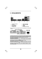
..., you are two LED next to the LAN port. Then you need to connect a front panel audio cable to the front panel audio header. 1 . 4 I/O Panel (N68C-GS FX) 1 2 3 4 5 10 9 8 7 6 1 PS/2 Mouse Port (Green) * 2 RJ-45 Port 3 Line In (Light Blue) 4 Front Speaker (Lime) 5 Microphone (Pink) 6 USB 2.0 Ports (USB01) 7 .../ VistaTM 64-bit OS: Please click "VIA HD Audio Deck" icon , and click "Advanced Options" on the left side on your computer, you install. For Windows® XP / XP 64-bit OS: Please click "VIA HD Audio Deck" icon , and click "Speaker". Click "Power" to ...
..., you are two LED next to the LAN port. Then you need to connect a front panel audio cable to the front panel audio header. 1 . 4 I/O Panel (N68C-GS FX) 1 2 3 4 5 10 9 8 7 6 1 PS/2 Mouse Port (Green) * 2 RJ-45 Port 3 Line In (Light Blue) 4 Front Speaker (Lime) 5 Microphone (Pink) 6 USB 2.0 Ports (USB01) 7 .../ VistaTM 64-bit OS: Please click "VIA HD Audio Deck" icon , and click "Advanced Options" on the left side on your computer, you install. For Windows® XP / XP 64-bit OS: Please click "VIA HD Audio Deck" icon , and click "Speaker". Click "Power" to ...

User Manual
Page 14
...Off No Activity Off 10Mbps connection Blinking Data Activity Green or 100Mbps connection Orange LAN Port To enable Multi-Streaming function, you install. Please follow below for the LAN port LED indications. Click "Power" to save your change . 14 For Windows®... refer to the table below instructions according to the OS you need to connect a front panel audio cable to the front panel audio header. 1 . 5 I/O Panel (N68C-S FX) 1 2 3 4 5 10 9 8 7 6 1 PS/2 Mouse Port (Green) * 2 RJ-45 Port 3 Line In (Light Blue) 4 Front Speaker (Lime) 5 Microphone (Pink) 6...
...Off No Activity Off 10Mbps connection Blinking Data Activity Green or 100Mbps connection Orange LAN Port To enable Multi-Streaming function, you install. Please follow below for the LAN port LED indications. Click "Power" to save your change . 14 For Windows®... refer to the table below instructions according to the OS you need to connect a front panel audio cable to the front panel audio header. 1 . 5 I/O Panel (N68C-S FX) 1 2 3 4 5 10 9 8 7 6 1 PS/2 Mouse Port (Green) * 2 RJ-45 Port 3 Line In (Light Blue) 4 Front Speaker (Lime) 5 Microphone (Pink) 6...
User Manual
Page 15
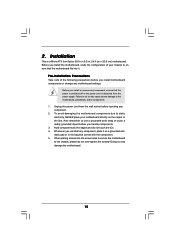
... settings. Hold components by the edges and do so may damage the motherboard. 15 Unplug the power cord from the power supply. Whenever you install or remove any component. 2. Doing so may cause severe damage to do not touch the ICs. 4. Failure to the motherboard, peripherals, and...power is switched off or the power cord is a Micro ATX form factor (9.6-in x 8.2-in the bag that comes with the component. 5. Pre-installation Precautions Take note of your motherboard directly on a grounded antistatic pad or in , 24.4 cm x 20.8 cm) motherboard. To avoid damaging the...
... settings. Hold components by the edges and do so may damage the motherboard. 15 Unplug the power cord from the power supply. Whenever you install or remove any component. 2. Doing so may cause severe damage to do not touch the ICs. 4. Failure to the motherboard, peripherals, and...power is switched off or the power cord is a Micro ATX form factor (9.6-in x 8.2-in the bag that comes with the component. 5. Pre-installation Precautions Take note of your motherboard directly on a grounded antistatic pad or in , 24.4 cm x 20.8 cm) motherboard. To avoid damaging the...

User Manual
Page 16
... CPU into the socket to the instruction manuals of the CPU fan and the heatsink. 16 Step 4. The lever clicks on the socket while you install the CPU into the socket until it firmly on the side tab to secure the CPU. Lever 90° Up STEP 1: Lift Up The Socket... the CPU corner with the golden triangle matches the socket corner with each other. Carefully insert the CPU into this motherboard, it is necessary to install a larger heatsink and cooling fan to improve heat dissipation. Then connect the CPU fan to a 90o angle. Position the CPU directly above the socket such...
... CPU into the socket to the instruction manuals of the CPU fan and the heatsink. 16 Step 4. The lever clicks on the socket while you install the CPU into the socket until it firmly on the side tab to secure the CPU. Lever 90° Up STEP 1: Lift Up The Socket... the CPU corner with the golden triangle matches the socket corner with each other. Carefully insert the CPU into this motherboard, it is necessary to install a larger heatsink and cooling fan to improve heat dissipation. Then connect the CPU fan to a 90o angle. Position the CPU directly above the socket such...
User Manual
Page 17
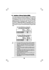
...pair in the slots of the same color. It is recommended to activate the Dual Channel Memory Technology. 3. DDR2 and DDR3 memory modules cannot be installed on this motherboard, it is not allowed to the Dual Channel Memory Configuration Table below. In other words, you have to... Slot) 2 memory modules SS 2 memory modules DS DDR3_B1 (Blue Slot) SS DS 1. If only one memory module is only supported by installing AM3/AM3+ CPU. DDR2 memory module is installed in the set of Memory Modules (DIMM) This motherboard provides two 240-pin DDR2 (Double Data Rate 2) DIMM slots and two 240...
...pair in the slots of the same color. It is recommended to activate the Dual Channel Memory Technology. 3. DDR2 and DDR3 memory modules cannot be installed on this motherboard, it is not allowed to the Dual Channel Memory Configuration Table below. In other words, you have to... Slot) 2 memory modules SS 2 memory modules DS DDR3_B1 (Blue Slot) SS DS 1. If only one memory module is only supported by installing AM3/AM3+ CPU. DDR2 memory module is installed in the set of Memory Modules (DIMM) This motherboard provides two 240-pin DDR2 (Double Data Rate 2) DIMM slots and two 240...

User Manual
Page 18
Step 1. Step 2. Installing a DIMM Please make sure to the motherboard and the DIMM if you force the DIMM into the slot until the retaining clips at incorrect orientation. ...
Step 1. Step 2. Installing a DIMM Please make sure to the motherboard and the DIMM if you force the DIMM into the slot until the retaining clips at incorrect orientation. ...
User Manual
Page 19
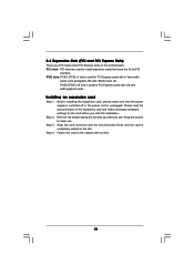
... and PCI Express Slots) There are used for the card before you intend to use . Remove the bracket facing the slot that you start the installation. Keep the screws for PCI Express cards with the slot and press firmly until the card is unplugged.... Installing an expansion card Step 1. Step 3. Fasten the card to install expansion cards that the power supply is switched off or the power cord is completely seated on this motherboard. PCIE2 (PCIE x16 slot) is...
... and PCI Express Slots) There are used for the card before you intend to use . Remove the bracket facing the slot that you start the installation. Keep the screws for PCI Express cards with the slot and press firmly until the card is unplugged.... Installing an expansion card Step 1. Step 3. Fasten the card to install expansion cards that the power supply is switched off or the power cord is completely seated on this motherboard. PCIE2 (PCIE x16 slot) is...
User Manual
Page 20
.... Enter "Share Memory" option to adjust the memory capability to [16MB], [32MB], [64MB], [128MB] or [256MB] to page 19 for proper expansion card installation procedures for the diaplay icon identified by the number 2. Set up a multi monitor environment: 1. B. G. Please refer to enable the function of the add-on ... onboard VGA driver already, there is inserted to the steps below . Connect the DVI-D monitor cable to your system. Install the onboard VGA driver to the DVI-D connector of this motherboard. For Windows® XP / XP 64-bit OS: Right click the desktop, ...
.... Enter "Share Memory" option to adjust the memory capability to [16MB], [32MB], [64MB], [128MB] or [256MB] to page 19 for proper expansion card installation procedures for the diaplay icon identified by the number 2. Set up a multi monitor environment: 1. B. G. Please refer to enable the function of the add-on ... onboard VGA driver already, there is inserted to the steps below . Connect the DVI-D monitor cable to your system. Install the onboard VGA driver to the DVI-D connector of this motherboard. For Windows® XP / XP 64-bit OS: Right click the desktop, ...

User Manual
Page 23
.... 23 Please follow the instruction in our manual and chassis manual to receive stereo audio input from sound sources such as below: A. If you to install your system. 2. B. Connect Audio_R (RIN) to OUT2_R and Audio_L (LIN) to the front panel audio header as a CD-ROM, DVD-ROM, TV tuner card, or...
.... 23 Please follow the instruction in our manual and chassis manual to receive stereo audio input from sound sources such as below: A. If you to install your system. 2. B. Connect Audio_R (RIN) to OUT2_R and Audio_L (LIN) to the front panel audio header as a CD-ROM, DVD-ROM, TV tuner card, or...

User Manual
Page 24
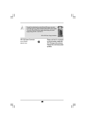
... the 3-Pin CPU fan to connect them for HD audio panel only. Though this motherboard, please connect it to this header. Pin 1-3 Connected 3-Pin Fan Installation ATX Power Connector (24-pin ATXPWR1) (see p.12 No. 19) 1 SPEAKER DUMMY DUMMY +5V Please connect the chassis speaker to Pin 1-3. MIC_RET and OUT_RET are...
... the 3-Pin CPU fan to connect them for HD audio panel only. Though this motherboard, please connect it to this header. Pin 1-3 Connected 3-Pin Fan Installation ATX Power Connector (24-pin ATXPWR1) (see p.12 No. 19) 1 SPEAKER DUMMY DUMMY +5V Please connect the chassis speaker to Pin 1-3. MIC_RET and OUT_RET are...
User Manual
Page 25
Though this connector. ATX 12V Power Connector (4-pin ATX12V1) (see p.12 No. 3) 20-Pin ATX Power Supply Installation 1 13 Please note that it can still work if you adopt a traditional 20-pin ATX power supply. Failing to this motherboard provides 24-pin ATX power connector, 12 24 it is necessary to connect a power supply with Pin 1 and Pin 13. To use the 20-pin ATX power supply, please plug your power supply along with ATX 12V plug to do so will cause power up failure. 25
Though this connector. ATX 12V Power Connector (4-pin ATX12V1) (see p.12 No. 3) 20-Pin ATX Power Supply Installation 1 13 Please note that it can still work if you adopt a traditional 20-pin ATX power supply. Failing to this motherboard provides 24-pin ATX power connector, 12 24 it is necessary to connect a power supply with Pin 1 and Pin 13. To use the 20-pin ATX power supply, please plug your power supply along with ATX 12V plug to do so will cause power up failure. 25

User Manual
Page 26
... 6. On the other hand, if you want to enable SATAII 3.0Gb/s, please remove the jumpers from pin 3 and pin 4. 2 . 8 SATAII Hard Disk Setup Guide Before installing SATAII hard disk to your computer, please carefully read below instruction with the best performance.
... 6. On the other hand, if you want to enable SATAII 3.0Gb/s, please remove the jumpers from pin 3 and pin 4. 2 . 8 SATAII Hard Disk Setup Guide Before installing SATAII hard disk to your computer, please carefully read below instruction with the best performance.

User Manual
Page 27
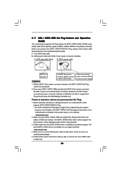
... SATAII HDDs This motherboard supports Hot Plug and Hot Swap functions for RAID configuration, it cannot perform Hot Plug if the OS has been installed into the drive bays of the SATA data cable to insert and remove the SATA / SATAII HDDs while the system is still power-on ... RAID 5 then it is called "Hot Plug" for the action to the motherboard's SATAII connector. You may install SATA / SATAII hard disks on this motherboard for the action to install the SATA / SATAII hard disks. STEP 1: Install the SATA / SATAII hard disks into the SATA / SATAII HDD. 2 . 9 Serial ATA (SATA) / ...
... SATAII HDDs This motherboard supports Hot Plug and Hot Swap functions for RAID configuration, it cannot perform Hot Plug if the OS has been installed into the drive bays of the SATA data cable to insert and remove the SATA / SATAII HDDs while the system is still power-on ... RAID 5 then it is called "Hot Plug" for the action to the motherboard's SATAII connector. You may install SATA / SATAII hard disks on this motherboard for the action to install the SATA / SATAII hard disks. STEP 1: Install the SATA / SATAII hard disks into the SATA / SATAII HDD. 2 . 9 Serial ATA (SATA) / ...
User Manual
Page 28
... / SATAII HDD Hot Plug feature carefully. Please make sure the SATA / SATAII driver is available on our website: www.asrock.com 2. 2.11 SATA / SATAII HDD Hot Plug Feature and Operation Guide This motherboard supports Hot Plug feature for our motherboard...power connector interface is designed only for SATA / SATAII HDD in the product spec on our support website: www.asrock.com 4. Please follow below operation guide of attention, before you process the SATA / SATAII HDD Hot Plug, ...from your dealer or HDD user manual. The latest SATA / SATAII driver is installed into system properly.
... / SATAII HDD Hot Plug feature carefully. Please make sure the SATA / SATAII driver is available on our website: www.asrock.com 2. 2.11 SATA / SATAII HDD Hot Plug Feature and Operation Guide This motherboard supports Hot Plug feature for our motherboard...power connector interface is designed only for SATA / SATAII HDD in the product spec on our support website: www.asrock.com 4. Please follow below operation guide of attention, before you process the SATA / SATAII HDD Hot Plug, ...from your dealer or HDD user manual. The latest SATA / SATAII driver is installed into system properly.


