User Manual
Page 10
... devices simultaneously and even supports continuous charging when your computer and up to update system BIOS without entering operating systems first like MS-DOS or Windows®. The software name itself - Please be noticed that the USB flash drive or hard drive must use Intelligent Energy Saver function, please enable Cool 'n' Quiet option in the BIOS setup in a few clicks without sacrificing computing performance. ASRock website: http://www.asrock...
... devices simultaneously and even supports continuous charging when your computer and up to update system BIOS without entering operating systems first like MS-DOS or Windows®. The software name itself - Please be noticed that the USB flash drive or hard drive must use Intelligent Energy Saver function, please enable Cool 'n' Quiet option in the BIOS setup in a few clicks without sacrificing computing performance. ASRock website: http://www.asrock...
User Manual
Page 12
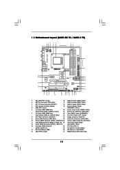
...) 2 CPU Fan Connector (CPU_FAN1) 17 USB 2.0 Header (USB6_7, Blue) 3 ATX 12V Power Connector (ATX12V1) 18 USB 2.0 Header (USB4_5, Blue) 4 CPU Heatsink Retention Module 19 Chassis Speaker Header 5 AMD CPU Socket (SPEAKER 1, White) 6 2 x 240-pin DDR2 DIMM Slots 20 System Panel Header (PANEL1, White) (Dual Channel: DDRII_1, DDRII_2; Blue) 23 Print Port Header (LPT1, Purple) 8 ATX Power Connector (ATXPWR1) 24 Floppy Connector (FLOPPY1) 9 Primary IDE Connector (IDE1, Blue) 25 Power Fan Connector (PWR_FAN1) 10 Primary SATAII Connector (SATAII_1 (PORT 0.0)) 26 Internal Audio Connector...
...) 2 CPU Fan Connector (CPU_FAN1) 17 USB 2.0 Header (USB6_7, Blue) 3 ATX 12V Power Connector (ATX12V1) 18 USB 2.0 Header (USB4_5, Blue) 4 CPU Heatsink Retention Module 19 Chassis Speaker Header 5 AMD CPU Socket (SPEAKER 1, White) 6 2 x 240-pin DDR2 DIMM Slots 20 System Panel Header (PANEL1, White) (Dual Channel: DDRII_1, DDRII_2; Blue) 23 Print Port Header (LPT1, Purple) 8 ATX Power Connector (ATXPWR1) 24 Floppy Connector (FLOPPY1) 9 Primary IDE Connector (IDE1, Blue) 25 Power Fan Connector (PWR_FAN1) 10 Primary SATAII Connector (SATAII_1 (PORT 0.0)) 26 Internal Audio Connector...
User Manual
Page 20
... DVI-D connector of the add-on PCI Express VGA card, you use multiple monitors with your card, one , two and three. C. Right-click the display icon and select "Attached", if necessary. F. 2.5 Easy Multi Monitor Feature This motherboard supports Multi Monitor upgrade. Boot your system. Press or to set up a multi-monitor display. B. A. Connect the DVI-D monitor cable to install it again. 5. Click the "Identify" button to page 19 for proper expansion card installation procedures for...
... DVI-D connector of the add-on PCI Express VGA card, you use multiple monitors with your card, one , two and three. C. Right-click the display icon and select "Attached", if necessary. F. 2.5 Easy Multi Monitor Feature This motherboard supports Multi Monitor upgrade. Boot your system. Press or to set up a multi-monitor display. B. A. Connect the DVI-D monitor cable to install it again. 5. Click the "Identify" button to page 19 for proper expansion card installation procedures for...

User Manual
Page 26
... remove the jumpers from pin 3 and pin 4. Please visit HITACHI's website for details: http://www.hitachigst.com/hdd/support/download.htm The above examples are just for your SATAII hard disk to SATAII mode in advance; For different SATAII hard disk products of SATAII hard disks may not be enabled. HITACHI Please use the Feature Tool, a DOS-bootable tool, for the updates. 26 2 . 8 SATAII Hard Disk Setup Guide Before installing SATAII hard disk to...
... remove the jumpers from pin 3 and pin 4. Please visit HITACHI's website for details: http://www.hitachigst.com/hdd/support/download.htm The above examples are just for your SATAII hard disk to SATAII mode in advance; For different SATAII hard disk products of SATAII hard disks may not be enabled. HITACHI Please use the Feature Tool, a DOS-bootable tool, for the updates. 26 2 . 8 SATAII Hard Disk Setup Guide Before installing SATAII hard disk to...
User Manual
Page 30
... boot-up to bottom side to change the BIOS setting. C. Insert the ASRock Support CD into your system. Therefore, the drivers you don't have to boot your optical drive to make a SATA / SATAII driver diskette. STEP 1: Set Up BIOS. Enter BIOS SETUP UTILITY Advanced screen Storage Configuration. Besides, there is no need for boot devices selection appears. Please follow below procedures according to the OS you install. 2.14.1 Installing Windows® XP / XP 64-bit With RAID...
... boot-up to bottom side to change the BIOS setting. C. Insert the ASRock Support CD into your system. Therefore, the drivers you don't have to boot your optical drive to make a SATA / SATAII driver diskette. STEP 1: Set Up BIOS. Enter BIOS SETUP UTILITY Advanced screen Storage Configuration. Besides, there is no need for boot devices selection appears. Please follow below procedures according to the OS you install. 2.14.1 Installing Windows® XP / XP 64-bit With RAID...
User Manual
Page 31
... install according to [RAID]. STEP 1: Set Up BIOS. B. Before you install. Enter BIOS SETUP UTILITY Advanced screen Storage Configuration. D. Set the "SATA Operation Mode" option to the mode you choose and the OS you start Please insert a floppy diskette into the floppy drive, and press any key. If you need to check the RAID installation guide in the Support CD: .. \ RAID Installation Guide 31 Please refer to check the RAID installation guide in the Support CD: .. \ RAID Installation Guide STEP 5: Install Windows® XP / XP 64-bit OS on IDE HDDs...
... install according to [RAID]. STEP 1: Set Up BIOS. B. Before you install. Enter BIOS SETUP UTILITY Advanced screen Storage Configuration. D. Set the "SATA Operation Mode" option to the mode you choose and the OS you start Please insert a floppy diskette into the floppy drive, and press any key. If you need to check the RAID installation guide in the Support CD: .. \ RAID Installation Guide 31 Please refer to check the RAID installation guide in the Support CD: .. \ RAID Installation Guide STEP 5: Install Windows® XP / XP 64-bit OS on IDE HDDs...
User Manual
Page 32
... driver to install Windows® 7 / 7 64-bit OS, and then install ASRock All-in-1 driver. 2 . 1 5 Untied Overclocking Technology This motherboard supports Untied Overclocking Technology, which means during overclocking, but PCI / PCIE buses are in the following path in BIOS first. page, please insert the ASRock Support CD into the optical drive again to [RAID] in the Support CD: .. \ RAID Installation Guide NOTE. If you enable Untied Overclocking function, please enter "Overclock Mode" option of BIOS setup to set the RAID configuration by using the Windows RAID installation guide...
... driver to install Windows® 7 / 7 64-bit OS, and then install ASRock All-in-1 driver. 2 . 1 5 Untied Overclocking Technology This motherboard supports Untied Overclocking Technology, which means during overclocking, but PCI / PCIE buses are in the following path in BIOS first. page, please insert the ASRock Support CD into the optical drive again to [RAID] in the Support CD: .. \ RAID Installation Guide NOTE. If you enable Untied Overclocking function, please enter "Overclock Mode" option of BIOS setup to set the RAID configuration by using the Windows RAID installation guide...

User Manual
Page 44
...HDDs can be accessed until you want to enable or disable the "OnBoard IDE Controller" feature. We will use the "IDE1 Master" as well. Onboard SATA Controller Use this option is [IDE]. 3.4.4 Storage Configuration BIOS SETUP UTILITY Advanced Storage Configuration Onboard IDE Controller Onboard SATA Controller SATA Operation Mode IDE1 Master IDE1 Slave SATAII_1 SATAII_2 SATAII_3 SATAII_4 [Enabled] [Enabled] [IDE] [Hard Disk] [Not Detected] [Not Detected] [Not Detected] [Not Detected] [Not Detected] Options Disabled Enabled +F1 F9 F10 ESC Select Screen Select Item Change...
...HDDs can be accessed until you want to enable or disable the "OnBoard IDE Controller" feature. We will use the "IDE1 Master" as well. Onboard SATA Controller Use this option is [IDE]. 3.4.4 Storage Configuration BIOS SETUP UTILITY Advanced Storage Configuration Onboard IDE Controller Onboard SATA Controller SATA Operation Mode IDE1 Master IDE1 Slave SATAII_1 SATAII_2 SATAII_3 SATAII_4 [Enabled] [Enabled] [IDE] [Hard Disk] [Not Detected] [Not Detected] [Not Detected] [Not Detected] [Not Detected] Options Disabled Enabled +F1 F9 F10 ESC Select Screen Select Item Change...

User Manual
Page 45
... IDE hard disk drives to active. [CD/DVD]:This is used for compatible IDE devices. DMA Mode DMA capability allows the improved transfer-speed and data-integrity for IDE ARMD (ATAPI Removable Media Device), such as FDISK, to partition and format the new IDE hard disk drives. Configuration options: [Disabled], [Auto], [Enabled]. 32Bit Data Transfer Use this item to enable 32-bit access to enable or disable the S.M.A.R.T. (Self-Monitoring, Analysis, and Reporting Technology) feature. TYPE Use this item to configure the type of the IDE device...
... IDE hard disk drives to active. [CD/DVD]:This is used for compatible IDE devices. DMA Mode DMA capability allows the improved transfer-speed and data-integrity for IDE ARMD (ATAPI Removable Media Device), such as FDISK, to partition and format the new IDE hard disk drives. Configuration options: [Disabled], [Auto], [Enabled]. 32Bit Data Transfer Use this item to enable 32-bit access to enable or disable the S.M.A.R.T. (Self-Monitoring, Analysis, and Reporting Technology) feature. TYPE Use this item to configure the type of the IDE device...

User Manual
Page 49
... to enable or disable USB Mouse Power On on the system. USB Keyboard/Remote Power On Use this item to enable or disable USB Keyboard/Remote Power On on the system. 49 Please refer to enable or disable the USB 2.0 support. 3.4.8USB Configuration BIOS SETUP UTILITY Advanced USB Configuration USB Controller USB 2.0 Support Legacy USB Support [Enabled] [Enabled] [Enabled] USB Keyboard/Remote Power On [Disabled] USB Mouse Power On [Disabled] To enable or disable the onboard USB controllers. +F1 F9 F10 ESC Select Screen Select Item Change Option General Help Load Defaults Save...
... to enable or disable USB Mouse Power On on the system. USB Keyboard/Remote Power On Use this item to enable or disable USB Keyboard/Remote Power On on the system. 49 Please refer to enable or disable the USB 2.0 support. 3.4.8USB Configuration BIOS SETUP UTILITY Advanced USB Configuration USB Controller USB 2.0 Support Legacy USB Support [Enabled] [Enabled] [Enabled] USB Keyboard/Remote Power On [Disabled] USB Mouse Power On [Disabled] To enable or disable the onboard USB controllers. +F1 F9 F10 ESC Select Screen Select Item Change Option General Help Load Defaults Save...
User Manual
Page 54
... available devices drivers if the system detects the installed devices. Please install the necessary drivers to visit ASRock's website at http://www.asrock.com; 4. Software Support 4.1 Install Operating System This motherboard supports various Microsoft® Windows® operating systems: 7 / 7 64-bit / VistaTM / VistaTM 64-bit / XP / XP 64-bit. Because motherboard settings and hardware options vary, use the setup procedures in this chapter for more about ASRock, welcome to activate the devices. 4.2.3 Utilities Menu The Utilities Menu shows...
... available devices drivers if the system detects the installed devices. Please install the necessary drivers to visit ASRock's website at http://www.asrock.com; 4. Software Support 4.1 Install Operating System This motherboard supports various Microsoft® Windows® operating systems: 7 / 7 64-bit / VistaTM / VistaTM 64-bit / XP / XP 64-bit. Because motherboard settings and hardware options vary, use the setup procedures in this chapter for more about ASRock, welcome to activate the devices. 4.2.3 Utilities Menu The Utilities Menu shows...
Quick Installation Guide
Page 2
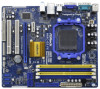
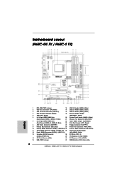
...14 SPI Flash Memory (8Mb) 30 PCI Express x1 Slot (PCIE1) 15 USB_PWR2 Jumper 31 NVIDIA GeForce 7025 / nForce 630a 2 ASRock N68C-GS FX / N68C-S FX Motherboard Motherboard Layout (N68C-GS FX / N68C-S FX) English 1 PS2_USB_PWR1 Jumper 16 USB 2.0 Header (USB8_9, Blue) 2 CPU Fan Connector (CPU_FAN1) 17 USB 2.0 Header (USB6_7, Blue) 3 ATX 12V Power Connector (ATX12V1) 18 USB 2.0 Header (USB4_5, Blue) 4 CPU Heatsink Retention Module 19 Chassis Speaker Header 5 AMD CPU Socket (SPEAKER 1, White) 6 2 x 240-pin DDR2 DIMM Slots 20 System Panel Header (PANEL1, White) (Dual Channel: DDRII_1...
...14 SPI Flash Memory (8Mb) 30 PCI Express x1 Slot (PCIE1) 15 USB_PWR2 Jumper 31 NVIDIA GeForce 7025 / nForce 630a 2 ASRock N68C-GS FX / N68C-S FX Motherboard Motherboard Layout (N68C-GS FX / N68C-S FX) English 1 PS2_USB_PWR1 Jumper 16 USB 2.0 Header (USB8_9, Blue) 2 CPU Fan Connector (CPU_FAN1) 17 USB 2.0 Header (USB6_7, Blue) 3 ATX 12V Power Connector (ATX12V1) 18 USB 2.0 Header (USB4_5, Blue) 4 CPU Heatsink Retention Module 19 Chassis Speaker Header 5 AMD CPU Socket (SPEAKER 1, White) 6 2 x 240-pin DDR2 DIMM Slots 20 System Panel Header (PANEL1, White) (Dual Channel: DDRII_1...
Quick Installation Guide
Page 7
...NB Voltage Multi-adjustment Support CD - OEM and Trial; ASRock Instant Boot English - ASRock XFast USB (see CAUTION 15) - - Supports "Plug and Play" - Drivers, Utilities, AntiVirus Software (Trial Version), CyberLink MediaEspresso 6.5 Trial, ASRock Software Suite (CyberLink DVD Suite - ASRock SmartView (see CAUTION 16) - CPU Frequency Stepless Control (see CAUTION 12) - CPU/Chassis/Power FAN connector - 24 pin ATX power connector - 4 pin 12V power connector - Creative Sound Blaster X-Fi MB - ASRock Instant Flash (see CAUTION 18) 7 ASRock N68C-GS FX / N68C-S FX...
...NB Voltage Multi-adjustment Support CD - OEM and Trial; ASRock Instant Boot English - ASRock XFast USB (see CAUTION 15) - - Supports "Plug and Play" - Drivers, Utilities, AntiVirus Software (Trial Version), CyberLink MediaEspresso 6.5 Trial, ASRock Software Suite (CyberLink DVD Suite - ASRock SmartView (see CAUTION 16) - CPU Frequency Stepless Control (see CAUTION 12) - CPU/Chassis/Power FAN connector - 24 pin ATX power connector - 4 pin 12V power connector - Creative Sound Blaster X-Fi MB - ASRock Instant Flash (see CAUTION 18) 7 ASRock N68C-GS FX / N68C-S FX...
Quick Installation Guide
Page 8
... realize that there is a certain risk involved with overclocking, including adjusting the setting in the BIOS, applying Untied Overclocking Technology, or using the third-party overclocking tools. English 8 ASRock N68C-GS FX / N68C-S FX Motherboard CPU/Chassis/Power Fan Tachometer - - CPU Temperature Sensing Monitor - Chassis Temperature Sensing - ASRock AM2 Boost: ASRock Patented Technology to boost memory performance up to the components and devices of your own risk and expense. CPU Quiet Fan - Overclocking may affect your system stability, or even cause...
... realize that there is a certain risk involved with overclocking, including adjusting the setting in the BIOS, applying Untied Overclocking Technology, or using the third-party overclocking tools. English 8 ASRock N68C-GS FX / N68C-S FX Motherboard CPU/Chassis/Power Fan Tachometer - - CPU Temperature Sensing Monitor - Chassis Temperature Sensing - ASRock AM2 Boost: ASRock Patented Technology to boost memory performance up to the components and devices of your own risk and expense. CPU Quiet Fan - Overclocking may affect your system stability, or even cause...
Quick Installation Guide
Page 10
.../index.asp 10 ASRock N68C-GS FX / N68C-S FX Motherboard English Please visit our website for the user to improve efficiency when the CPU cores are idle. Just launch this utility, you to RAM (S3), hibernation mode (S4) or power off (S5). ASRock APP Charger allows you can press key during the POST or press key to BIOS setup menu to quickly charge many Apple devices simultaneously and even supports continuous charging when...
.../index.asp 10 ASRock N68C-GS FX / N68C-S FX Motherboard English Please visit our website for the user to improve efficiency when the CPU cores are idle. Just launch this utility, you to RAM (S3), hibernation mode (S4) or power off (S5). ASRock APP Charger allows you can press key during the POST or press key to BIOS setup menu to quickly charge many Apple devices simultaneously and even supports continuous charging when...
Quick Installation Guide
Page 17
... ASRock N68C-GS FX / N68C-S FX Motherboard English Please refer to the D-Sub connector of onboard VGA/D-sub. Connect another D-Sub monitor cable to page 16 for proper expansion card installation procedures for the second monitor. B. F. G. With the internal onboard VGA and the external add-on PCI Express VGA card. Please refer to the following steps to enable the function of the add-on PCI Express VGA card, you select is no need to enter BIOS setup. Enter "Share Memory" option to adjust the memory...
... ASRock N68C-GS FX / N68C-S FX Motherboard English Please refer to the D-Sub connector of onboard VGA/D-sub. Connect another D-Sub monitor cable to page 16 for proper expansion card installation procedures for the second monitor. B. F. G. With the internal onboard VGA and the external add-on PCI Express VGA card. Please refer to the following steps to enable the function of the add-on PCI Express VGA card, you select is no need to enter BIOS setup. Enter "Share Memory" option to adjust the memory...
Quick Installation Guide
Page 24
... 64-bit Without RAID Functions If you apply Untied Overclocking Technology. 24 ASRock N68C-GS FX / N68C-S FX Motherboard English Before you enable Untied Overclocking function, please enter "Overclock Mode" option of BIOS setup to set the selection from up to bottom side to install Windows® 7 / 7 64-bit / VistaTM / VistaTM 64-bit / XP / XP 64-bit on page 8 for the possible overclocking risk before you just want to install those required drivers. Therefore, the drivers you to fixed PCI / PCIE...
... 64-bit Without RAID Functions If you apply Untied Overclocking Technology. 24 ASRock N68C-GS FX / N68C-S FX Motherboard English Before you enable Untied Overclocking function, please enter "Overclock Mode" option of BIOS setup to set the selection from up to bottom side to install Windows® 7 / 7 64-bit / VistaTM / VistaTM 64-bit / XP / XP 64-bit on page 8 for the possible overclocking risk before you just want to install those required drivers. Therefore, the drivers you to fixed PCI / PCIE...
Quick Installation Guide
Page 25
... to display the menus. 25 ASRock N68C-GS FX / N68C-S FX Motherboard English The BIOS Setup program is designed to select among the predetermined choices. If the Main Menu does not appear automatically, locate and doubleclick on the motherboard stores BIOS Setup Utility. BIOS Information The Flash Memory on the file "ASSETUP.EXE" from the "BIN" folder in the Support CD to enter BIOS Setup after POST, please restart the system by pressing + + , or pressing the reset button...
... to display the menus. 25 ASRock N68C-GS FX / N68C-S FX Motherboard English The BIOS Setup program is designed to select among the predetermined choices. If the Main Menu does not appear automatically, locate and doubleclick on the motherboard stores BIOS Setup Utility. BIOS Information The Flash Memory on the file "ASSETUP.EXE" from the "BIN" folder in the Support CD to enter BIOS Setup after POST, please restart the system by pressing + + , or pressing the reset button...
RAID Installation Guide
Page 7
... ASRock Support CD into the optical drive to boot your system, and follow the instruction to install Windows® 7 / 7 64-bit / VistaTM / VistaTM 64-bit on your SATA / SATAII HDDs with RAID functions, please follow below steps. For Windows® 7 / 7 64-bit users, you do you want to check the RAID installation guide in BIOS first. Set the "SATA Operation Mode" option to set the RAID configuration by using the Windows RAID installation guide in the following path in -1 driver. 7 STEP 2: Use "RAID Installation Guide" to [RAID]. 1.3.2 Installing Windows...
... ASRock Support CD into the optical drive to boot your system, and follow the instruction to install Windows® 7 / 7 64-bit / VistaTM / VistaTM 64-bit on your SATA / SATAII HDDs with RAID functions, please follow below steps. For Windows® 7 / 7 64-bit users, you do you want to check the RAID installation guide in BIOS first. Set the "SATA Operation Mode" option to set the RAID configuration by using the Windows RAID installation guide in the following path in -1 driver. 7 STEP 2: Use "RAID Installation Guide" to [RAID]. 1.3.2 Installing Windows...
RAID Installation Guide
Page 11
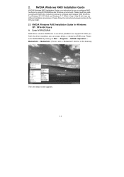
... instructions below according to configure and manage RAID functions. Please follow the instructions below screen appears. 11 Please enter NVRAIDMAN by using NVIDIAMAN under Windows environment. Enter NVRAIDMAN RAID driver is also a "Mediashield" shortcut on the desktop.) Then, the below to the OS you install. 2.1 NVIDIA Windows RAID Installation Guide for you can create, delete, or rebuild any RAID array. NVIDIA Windows RAID Installation Guide NVIDIA Windows RAID Installation Guide is an instruction for Windows XP / XP 64-bit Users...
... instructions below according to configure and manage RAID functions. Please follow the instructions below screen appears. 11 Please enter NVRAIDMAN by using NVIDIAMAN under Windows environment. Enter NVRAIDMAN RAID driver is also a "Mediashield" shortcut on the desktop.) Then, the below to the OS you install. 2.1 NVIDIA Windows RAID Installation Guide for you can create, delete, or rebuild any RAID array. NVIDIA Windows RAID Installation Guide NVIDIA Windows RAID Installation Guide is an instruction for Windows XP / XP 64-bit Users...


