User Manual
Page 11
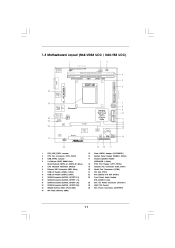
...) PCI Express x16 Slot (PCIE1) Front Panel Audio Header (HD_AUDIO1, Lime) ATX 12V Power Connector (ATX12V1) AM3 CPU Socket ATX Power Connector (ATXPWR1) 11 1.3 Motherboard L ayout (N68VGS3 UCC / N68VS3 UCC) Layout (N68-VGS3 N68-VS3 1 17.8cm (7.0-in) 2 3 Support 6-Core CPU 1 PS2_USB_PWR1 USB 2.0 T: USB2 B: USB3 21.6cm (8.5-in) 26 ATXPWR1 PS2 Keyboard PS2 Mouse 1 USB_PWR2 CPU_FAN1 DDR3_B1 (64...
...) PCI Express x16 Slot (PCIE1) Front Panel Audio Header (HD_AUDIO1, Lime) ATX 12V Power Connector (ATX12V1) AM3 CPU Socket ATX Power Connector (ATXPWR1) 11 1.3 Motherboard L ayout (N68VGS3 UCC / N68VS3 UCC) Layout (N68-VGS3 N68-VS3 1 17.8cm (7.0-in) 2 3 Support 6-Core CPU 1 PS2_USB_PWR1 USB 2.0 T: USB2 B: USB3 21.6cm (8.5-in) 26 ATXPWR1 PS2 Keyboard PS2 Mouse 1 USB_PWR2 CPU_FAN1 DDR3_B1 (64...
User Manual
Page 15
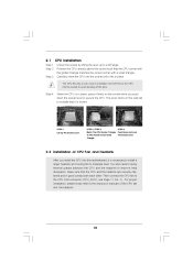
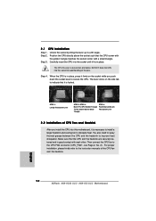
...socket while you install the CPU into the socket to dissipate heat. Make sure that the CPU corner with the golden triangle matches the socket corner with each other. Carefully insert the CPU into the socket until it is locked. Then connect the CPU fan to a 90 angle. Position the CPU directly above the socket such that the CPU...; Up CPU Golden Triangle Socker Corner Small Triangle STEP 1: Lift Up The Socket Lever STEP 2 / STEP 3: Match The CPU Golden Triangle To The Socket Corner Small Triangle STEP 4: Push Down And Lock The Socket Lever 2.2 Installation of the CPU fan and...
...socket while you install the CPU into the socket to dissipate heat. Make sure that the CPU corner with the golden triangle matches the socket corner with each other. Carefully insert the CPU into the socket until it is locked. Then connect the CPU fan to a 90 angle. Position the CPU directly above the socket such that the CPU...; Up CPU Golden Triangle Socker Corner Small Triangle STEP 1: Lift Up The Socket Lever STEP 2 / STEP 3: Match The CPU Golden Triangle To The Socket Corner Small Triangle STEP 4: Push Down And Lock The Socket Lever 2.2 Installation of the CPU fan and...
Quick Installation Guide
Page 2
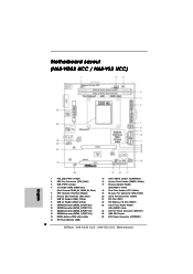
Blue) 5 CPU Heatsink Retention Module 6 Primary IDE Connector (IDE1, Blue) 7 USB 2.0 Header (USB6_7, Blue) 8 USB 2.0 Header (USB4_5, Blue) 9 SATAII Connector (SATAII_2 (PORT 0.1)) 10 SATAII ...PCI Express x16 Slot (PCIE1) 23 Front Panel Audio Header (HD_AUDIO1, Lime) 24 ATX 12V Power Connector (ATX12V1) 25 AM3 CPU Socket 26 ATX Power Connector (ATXPWR1) 2 ASRock N68-VGS3 UCC / N68-VS3 UCC Motherboard Motherboard Layout (N68-VGS3 UCC / N68-VS3 UCC) English 1 PS2_USB_PWR1 Jumper 2 CPU Fan Connector (CPU_FAN1) 3 USB_PWR2 Jumper 4 2 x 240-pin DDR3 DIMM Slots (Dual Channel: DDR3_A1, DDR3_B1;
Blue) 5 CPU Heatsink Retention Module 6 Primary IDE Connector (IDE1, Blue) 7 USB 2.0 Header (USB6_7, Blue) 8 USB 2.0 Header (USB4_5, Blue) 9 SATAII Connector (SATAII_2 (PORT 0.1)) 10 SATAII ...PCI Express x16 Slot (PCIE1) 23 Front Panel Audio Header (HD_AUDIO1, Lime) 24 ATX 12V Power Connector (ATX12V1) 25 AM3 CPU Socket 26 ATX Power Connector (ATXPWR1) 2 ASRock N68-VGS3 UCC / N68-VS3 UCC Motherboard Motherboard Layout (N68-VGS3 UCC / N68-VS3 UCC) English 1 PS2_USB_PWR1 Jumper 2 CPU Fan Connector (CPU_FAN1) 3 USB_PWR2 Jumper 4 2 x 240-pin DDR3 DIMM Slots (Dual Channel: DDR3_A1, DDR3_B1;
Quick Installation Guide
Page 12
... you push down the socket lever to secure the CPU. Step 2. When the CPU is in place. Then connect the CPU fan to dissipate heat. English 12 ASRock N68-VGS3 UCC / N68-VS3 UCC Motherboard Step 3. Carefully insert the CPU into the socket until it is locked. The lever clicks on the socket while you install the CPU into the socket to indicate that the...
... you push down the socket lever to secure the CPU. Step 2. When the CPU is in place. Then connect the CPU fan to dissipate heat. English 12 ASRock N68-VGS3 UCC / N68-VS3 UCC Motherboard Step 3. Carefully insert the CPU into the socket until it is locked. The lever clicks on the socket while you install the CPU into the socket to indicate that the...


