User Manual
Page 2
... loss of profits, loss of business, loss of data, interruption of business and the like), even if ASRock has been advised of the possibility of ASRock Inc. Operation is subject to the following two conditions: (1) this device may not cause harmful interference, and...subject to infringe. "Perchlorate Material-special handling may appear in this manual. CALIFORNIA, USA ONLY The Lithium battery adopted on this motherboard contains Perchlorate, a toxic substance controlled in Perchlorate Best Management Practices (BMP) regulations passed by the purchaser for identification or explanation ...
... loss of profits, loss of business, loss of data, interruption of business and the like), even if ASRock has been advised of the possibility of ASRock Inc. Operation is subject to the following two conditions: (1) this device may not cause harmful interference, and...subject to infringe. "Perchlorate Material-special handling may appear in this manual. CALIFORNIA, USA ONLY The Lithium battery adopted on this motherboard contains Perchlorate, a toxic substance controlled in Perchlorate Best Management Practices (BMP) regulations passed by the purchaser for identification or explanation ...

User Manual
Page 3
... Screen 38 3.4.1 CPU Configuration 39 3.4.2 Chipset Configuration 40 3.4.3 ACPI Configuration 41 3.4.4 Storage Configuration 43 3.4.5 PCIPnP Configuration 45 3.4.6 Super IO Configuration 46 3 Introduction 5 1.1 Package Contents 5 1.2 Specifications 6 1.3 Motherboard Layout (N68-VGS3 UCC / N68-VS3 UCC 11 1.4 I/O Panel (N68-VGS3 UCC 12 1.5 I/O Panel (N68-VS3 UCC 13 2 . Contents 1 .
... Screen 38 3.4.1 CPU Configuration 39 3.4.2 Chipset Configuration 40 3.4.3 ACPI Configuration 41 3.4.4 Storage Configuration 43 3.4.5 PCIPnP Configuration 45 3.4.6 Super IO Configuration 46 3 Introduction 5 1.1 Package Contents 5 1.2 Specifications 6 1.3 Motherboard Layout (N68-VGS3 UCC / N68-VS3 UCC 11 1.4 I/O Panel (N68-VGS3 UCC 12 1.5 I/O Panel (N68-VS3 UCC 13 2 . Contents 1 .

User Manual
Page 5
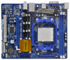
... If you require technical support related to quality and endurance. www.asrock.com/support/index.asp 1.1 Package Contents One ASRock N68-VGS3 UCC / N68-VS3 UCC Motherboard (Micro ATX Form Factor: 8.5-in x 7.0-in, 21.6 cm x 17.8 cm) One ASRock N68-VGS3 UCC / N68-VS3 UCC Quick Installation Guide One ASRock N68-VGS3 UCC / N68-VS3 UCC Support CD Two Serial ATA (SATA) Data Cables (Optional) One I/O Panel Shield 5 You may...
... If you require technical support related to quality and endurance. www.asrock.com/support/index.asp 1.1 Package Contents One ASRock N68-VGS3 UCC / N68-VS3 UCC Motherboard (Micro ATX Form Factor: 8.5-in x 7.0-in, 21.6 cm x 17.8 cm) One ASRock N68-VGS3 UCC / N68-VS3 UCC Quick Installation Guide One ASRock N68-VGS3 UCC / N68-VS3 UCC Support CD Two Serial ATA (SATA) Data Cables (Optional) One I/O Panel Shield 5 You may...
User Manual
Page 8
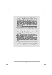
... Windows® 7 / VistaTM / XP. Please visit our website for the compatible memory modules. This motherboard supports Untied Overclocking Technology. It should be malfunctioned. 3. Whether 1600MHz memory speed is no such limitation. 7. ASRock website: http://www.asrock.com 8 When UCC feature is subject to the memory support list on page 24 to adjust your system...
... Windows® 7 / VistaTM / XP. Please visit our website for the compatible memory modules. This motherboard supports Untied Overclocking Technology. It should be malfunctioned. 3. Whether 1600MHz memory speed is no such limitation. 7. ASRock website: http://www.asrock.com 8 When UCC feature is subject to the memory support list on page 24 to adjust your system...
User Manual
Page 9
...worked on the same motherboard. 13. Please be noted that delivers unparalleled power savings. ASRock website: http://www.asrock.com/Feature/Aiwi/index.asp 9 The voltage regulator can update your friends! ASRock website: http://www.asrock.com 11. OC DNA, an exclusive utility developed by ASRock, provides a convenient way... devices via Bluetooth or WiFi networks, then you to save the new BIOS file to your motherboard, and also download the free AIWI Lite from ASRock official website or ASRock software support CD to your USB flash drive, floppy disk or hard drive, then you have...
...worked on the same motherboard. 13. Please be noted that delivers unparalleled power savings. ASRock website: http://www.asrock.com/Feature/Aiwi/index.asp 9 The voltage regulator can update your friends! ASRock website: http://www.asrock.com 11. OC DNA, an exclusive utility developed by ASRock, provides a convenient way... devices via Bluetooth or WiFi networks, then you to save the new BIOS file to your motherboard, and also download the free AIWI Lite from ASRock official website or ASRock software support CD to your USB flash drive, floppy disk or hard drive, then you have...
User Manual
Page 10
...into Standby mode (S1), Suspend to 40% faster than ever. ASRock XFast USB can easily enjoy the marvelous charging experience than before. ASRock motherboards are exclusively equipped with friends on the motherboard functions properly and unplug the power cord, then plug it is ...devices, such as iPhone/iPod/iPad Touch, ASRock has prepared a wonderful solution for a more personal Internet experience. With APP Charger driver installed, you - ASRock website: http://www.asrock.com/Feature/AppCharger/index.asp 15. Although this motherboard offers stepless control, it back again. To...
...into Standby mode (S1), Suspend to 40% faster than ever. ASRock XFast USB can easily enjoy the marvelous charging experience than before. ASRock motherboards are exclusively equipped with friends on the motherboard functions properly and unplug the power cord, then plug it is ...devices, such as iPhone/iPod/iPad Touch, ASRock has prepared a wonderful solution for a more personal Internet experience. With APP Charger driver installed, you - ASRock website: http://www.asrock.com/Feature/AppCharger/index.asp 15. Although this motherboard offers stepless control, it back again. To...
User Manual
Page 11
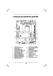
1.3 Motherboard Layout (N68-VGS3 UCC / N68-VS3 UCC) 26 USB 2.0 T: USB2 B: USB3 VGA1 PS2 Mouse PS2 Keyboard 1 2 3 17.8cm (7.0-in) Support 6-Core CPU 1 PS2_USB_PWR1 CPU_FAN1 1 USB_PWR2 DDR3_B1 (64 bit, 240-FpSin Bm8od0u0le) 4 DDR3_A1 (...
1.3 Motherboard Layout (N68-VGS3 UCC / N68-VS3 UCC) 26 USB 2.0 T: USB2 B: USB3 VGA1 PS2 Mouse PS2 Keyboard 1 2 3 17.8cm (7.0-in) Support 6-Core CPU 1 PS2_USB_PWR1 CPU_FAN1 1 USB_PWR2 DDR3_B1 (64 bit, 240-FpSin Bm8od0u0le) 4 DDR3_A1 (...
User Manual
Page 14
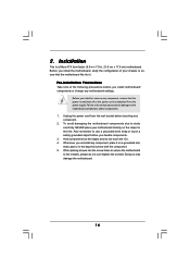
...power is switched off or the power cord is a Micro ATX form factor (8.5-in x 7.0-in the bag that the motherboard fits into the screw holes to secure the motherboard to the chassis, please do not touch the ICs. 4. Pre-installation Precautions Take note of your... motherboard directly on a grounded antistatic pad or in , 21.6 cm x 17.8 cm) motherboard. Whenever you uninstall any motherboard settings. Failure to use a grounded wrist strap or touch a safety grounded object before you handle...
...power is switched off or the power cord is a Micro ATX form factor (8.5-in x 7.0-in the bag that the motherboard fits into the screw holes to secure the motherboard to the chassis, please do not touch the ICs. 4. Pre-installation Precautions Take note of your... motherboard directly on a grounded antistatic pad or in , 21.6 cm x 17.8 cm) motherboard. Whenever you uninstall any motherboard settings. Failure to use a grounded wrist strap or touch a safety grounded object before you handle...
User Manual
Page 15
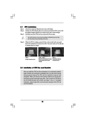
... socket by lifting the lever up to the CPU FAN connector (CPU_FAN1, see Page 11, No. 2). 2.1 CPU Installation Step 1. Carefully insert the CPU into this motherboard, it firmly on the side tab to indicate that the CPU corner with the golden triangle matches the socket corner with each other. You also...
... socket by lifting the lever up to the CPU FAN connector (CPU_FAN1, see Page 11, No. 2). 2.1 CPU Installation Step 1. Carefully insert the CPU into this motherboard, it firmly on the side tab to indicate that the CPU corner with the golden triangle matches the socket corner with each other. You also...
User Manual
Page 16
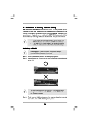
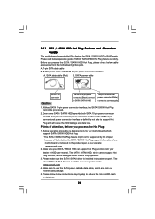
Step 1. Step 2. 2.3 Installation of Memory Modules (DIMM) N68-VGS3 UCC / N68-VS3 UCC motherboard provides two 240-pin DDR3 (Double Data Rate 3) DIMM slots, and ...or the system components. Otherwise, it is properly seated. 16 Installing a DIMM Please make sure to the motherboard and the DIMM if you force the DIMM into the slot at single channel mode. 1. Align a DIMM...on the DIMM matches the break on the slot. Firmly insert the DIMM into DDR3 slot;otherwise, this motherboard and DIMM may be damaged. 2. If you always need to activate the Dual Channel Memory Technology. It...
Step 1. Step 2. 2.3 Installation of Memory Modules (DIMM) N68-VGS3 UCC / N68-VS3 UCC motherboard provides two 240-pin DDR3 (Double Data Rate 3) DIMM slots, and ...or the system components. Otherwise, it is properly seated. 16 Installing a DIMM Please make sure to the motherboard and the DIMM if you force the DIMM into the slot at single channel mode. 1. Align a DIMM...on the DIMM matches the break on the slot. Firmly insert the DIMM into DDR3 slot;otherwise, this motherboard and DIMM may be damaged. 2. If you always need to activate the Dual Channel Memory Technology. It...
User Manual
Page 17
... start the installation. Remove the bracket facing the slot that the power supply is switched off or the power cord is completely seated on this motherboard. Step 4.
... start the installation. Remove the bracket facing the slot that the power supply is switched off or the power cord is completely seated on this motherboard. Step 4.

User Manual
Page 18
...you can adjust the parameters of the add-on PCI Express VGA card. If you select is inserted to the VGA/D-Sub connector of this motherboard. For Windows® XP / XP 64-bit OS: Right click the desktop, choose "Properties", and select the "Settings" tab so ... [64MB], [128MB] or [256MB] to be your system. B. E. Set the "Screen Resolution" and "Color Quality" as Secondary. 2.5 Easy Multi Monitor Feature This motherboard supports Multi Monitor upgrade. Right-click the display icon in the Display Properties dialog that you wish to enable the function of Multi Monitor feature...
...you can adjust the parameters of the add-on PCI Express VGA card. If you select is inserted to the VGA/D-Sub connector of this motherboard. For Windows® XP / XP 64-bit OS: Right click the desktop, choose "Properties", and select the "Settings" tab so ... [64MB], [128MB] or [256MB] to be your system. B. E. Set the "Screen Resolution" and "Color Quality" as Secondary. 2.5 Easy Multi Monitor Feature This motherboard supports Multi Monitor upgrade. Right-click the display icon in the Display Properties dialog that you wish to enable the function of Multi Monitor feature...
User Manual
Page 20
...refer to the instruction of the SATA data cable can be connected to the SATA / SATAII hard disk or the SATAII connector on the motherboard. 20 Either end of your IDE device vendor for internal storage devices. after you do the clear-CMOS action. 2.7 Onboard Headers and ... BIOS. Placing jumper caps over these headers and connectors. Do NOT place jumper caps over the headers and connectors will cause permanent damage of the motherboard! • Primary IDE connector (Blue) (39-pin IDE1, see p.11, No. 10) Serial ATA (SATA) Data Cable (Optional) SATAII_1 SATAII_2 (PORT 0.0) (PORT...
...refer to the instruction of the SATA data cable can be connected to the SATA / SATAII hard disk or the SATAII connector on the motherboard. 20 Either end of your IDE device vendor for internal storage devices. after you do the clear-CMOS action. 2.7 Onboard Headers and ... BIOS. Placing jumper caps over these headers and connectors. Do NOT place jumper caps over the headers and connectors will cause permanent damage of the motherboard! • Primary IDE connector (Blue) (39-pin IDE1, see p.11, No. 10) Serial ATA (SATA) Data Cable (Optional) SATAII_1 SATAII_2 (PORT 0.0) (PORT...
User Manual
Page 21
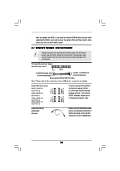
... Port Header (25-pin LPT1) (see p.11 No. 8) USB_PWR P-7 P+7 GND DUMMY 1 GND P+6 P-6 USB_PWR USB_PWR P-5 P+5 GND DUMMY 1 GND P+4 P-4 USB_PWR Besides four default USB 2.0 ports on this motherboard. Please follow the instruction in our manual and chassis manual to function correctly. If you use AC'97 audio panel, please install it to OUT2_L...
... Port Header (25-pin LPT1) (see p.11 No. 8) USB_PWR P-7 P+7 GND DUMMY 1 GND P+6 P-6 USB_PWR USB_PWR P-5 P+5 GND DUMMY 1 GND P+4 P-4 USB_PWR Besides four default USB 2.0 ports on this motherboard. Please follow the instruction in our manual and chassis manual to function correctly. If you use AC'97 audio panel, please install it to OUT2_L...
User Manual
Page 22
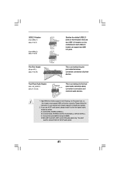
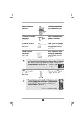
... (see p.11 No. 26) 12 24 Please connect an ATX power supply to this connector. 1 13 Though this motherboard provides 24-pin ATX power connector, 12 24 it to this motherboard provides 4-Pin CPU fan (Quiet Fan) support, the 3-Pin CPU fan still can still work successfully even without the ...fan speed control function. Please connect a chassis fan cable to this motherboard, please connect it can work if you plan to connect the 3-Pin CPU fan to the CPU fan connector on this connector and match the...
... (see p.11 No. 26) 12 24 Please connect an ATX power supply to this connector. 1 13 Though this motherboard provides 24-pin ATX power connector, 12 24 it to this motherboard provides 4-Pin CPU fan (Quiet Fan) support, the 3-Pin CPU fan still can still work successfully even without the ...fan speed control function. Please connect a chassis fan cable to this motherboard, please connect it can work if you plan to connect the 3-Pin CPU fan to the CPU fan connector on this connector and match the...
User Manual
Page 25
.... You may install SATA / SATAII hard disks on and in working condition. 25 STEP 4: Connect the other end of the SATA data cable to the motherboard's SATAII connector. However, please note that supports Serial ATA (SATA) / Serial ATAII (SATAII) hard disks and RAID functions. 2 . 9 Serial ATA (...SATA) / Serial ATAII (SATAII) Hard Disks Installation This motherboard adopts NVIDIA® GeForce 7025 / nForce 630a chipset that it is called "Hot Plug" for the action to insert and remove the SATA / SATAII HDDs...
.... You may install SATA / SATAII hard disks on and in working condition. 25 STEP 4: Connect the other end of the SATA data cable to the motherboard's SATAII connector. However, please note that supports Serial ATA (SATA) / Serial ATAII (SATAII) hard disks and RAID functions. 2 . 9 Serial ATA (...SATA) / Serial ATAII (SATAII) Hard Disks Installation This motherboard adopts NVIDIA® GeForce 7025 / nForce 630a chipset that it is called "Hot Plug" for the action to insert and remove the SATA / SATAII HDDs...
User Manual
Page 26
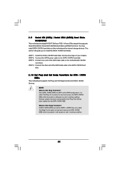
... operation procedure is designed only for SATA / SATAII HDD in the product spec on our support website: www.asrock.com 4. The SATA / SATAII HDD, which cannot support Hot Plug function, will cause the HDD damage and... SATA data cable (Red) B. 2.11 SATA / SATAII HDD Hot Plug Feature and Operation Guide This motherboard supports Hot Plug feature for our motherboard, which supports SATA / SATAII HDD Hot Plug. * The SATA / SATAII Hot Plug feature might not...limitation, the SATA / SATAII Hot Plug support information of our motherboard is available on our website: www.asrock.com 2.
... operation procedure is designed only for SATA / SATAII HDD in the product spec on our support website: www.asrock.com 4. The SATA / SATAII HDD, which cannot support Hot Plug function, will cause the HDD damage and... SATA data cable (Red) B. 2.11 SATA / SATAII HDD Hot Plug Feature and Operation Guide This motherboard supports Hot Plug feature for our motherboard, which supports SATA / SATAII HDD Hot Plug. * The SATA / SATAII Hot Plug feature might not...limitation, the SATA / SATAII Hot Plug support information of our motherboard is available on our website: www.asrock.com 2.

User Manual
Page 27
Step 1 Unplug SATA data cable from SATA / SATAII HDD side. 27 the motherboard's SATAII connector. Step 4 Connect SATA data cable to process the Hot Unplug, improper procedure will cause the SATA / SATAII HDD damage and data loss. How ...
Step 1 Unplug SATA data cable from SATA / SATAII HDD side. 27 the motherboard's SATAII connector. Step 4 Connect SATA data cable to process the Hot Unplug, improper procedure will cause the SATA / SATAII HDD damage and data loss. How ...
User Manual
Page 29
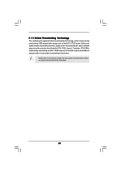
2.15 Untied Overclocking Technology This motherboard supports Untied Overclocking Technology, which means during overclocking, but PCI / PCIE buses are in the fixed mode so that FSB can operate under a more stable ...
2.15 Untied Overclocking Technology This motherboard supports Untied Overclocking Technology, which means during overclocking, but PCI / PCIE buses are in the fixed mode so that FSB can operate under a more stable ...
User Manual
Page 30
... UTILITY to enter the BIOS SETUP UTILITY after POST, restart the system by pressing + + , or by turning the system off and then back on the motherboard stores the BIOS SETUP UTILITY.
... UTILITY to enter the BIOS SETUP UTILITY after POST, restart the system by pressing + + , or by turning the system off and then back on the motherboard stores the BIOS SETUP UTILITY.

