
User Manual
Page 3
...Configuration 35 3.4.7 USB Configuration 36 3.5 Hardware Health Event Monitoring Screen 37 3.6 Boot Screen 38 3.6.1 Boot Settings Configuration 38 3.7 Security Screen 39 3.8 Exit Screen 40 3 Installation 14 Pre-installation Precautions 14 2.1 CPU Installation 15 2.2 Installation of CPU Fan and Heatsink 15 2.3 Installation of Memory Modules (DIMM 16 2.4 Expansion Slots (PCI and PCI Express Slots 17 2.5 Jumpers Setup 18 2.6 Onboard Headers and Connectors 19 3 . Contents 1 . Introduction 5 1.1 Package Contents 5 1.2 Specifications 6 1.3 Motherboard Layout 10 1.4 I/O Panel...
...Configuration 35 3.4.7 USB Configuration 36 3.5 Hardware Health Event Monitoring Screen 37 3.6 Boot Screen 38 3.6.1 Boot Settings Configuration 38 3.7 Security Screen 39 3.8 Exit Screen 40 3 Installation 14 Pre-installation Precautions 14 2.1 CPU Installation 15 2.2 Installation of CPU Fan and Heatsink 15 2.3 Installation of Memory Modules (DIMM 16 2.4 Expansion Slots (PCI and PCI Express Slots 17 2.5 Jumpers Setup 18 2.6 Onboard Headers and Connectors 19 3 . Contents 1 . Introduction 5 1.1 Package Contents 5 1.2 Specifications 6 1.3 Motherboard Layout 10 1.4 I/O Panel...

User Manual
Page 5
.... In case any modifications of this motherboard, please visit our website for specific information about the model you for purchasing ASRock N68-GS4/USB3 FX R2.0 / N68-GS4 FX R2.0 motherboard, a reliable motherboard produced under ASRock's consistently stringent quality control. www.asrock.com/support/index.asp 1.1 Package Contents ASRock N68-GS4/USB3 FX R2.0 / N68-GS4 FX R2.0 Motherboard (Micro ATX Form Factor) ASRock N68-GS4/USB3 FX R2.0 / N68-GS4 FX R2.0X Quick Installation Guide ASRock N68-GS4/USB3 FX R2.0 / N68-GS4 FX R2.0 Support CD 2 x Serial ATA (SATA) Data Cables (Optional...
.... In case any modifications of this motherboard, please visit our website for specific information about the model you for purchasing ASRock N68-GS4/USB3 FX R2.0 / N68-GS4 FX R2.0 motherboard, a reliable motherboard produced under ASRock's consistently stringent quality control. www.asrock.com/support/index.asp 1.1 Package Contents ASRock N68-GS4/USB3 FX R2.0 / N68-GS4 FX R2.0 Motherboard (Micro ATX Form Factor) ASRock N68-GS4/USB3 FX R2.0 / N68-GS4 FX R2.0X Quick Installation Guide ASRock N68-GS4/USB3 FX R2.0 / N68-GS4 FX R2.0 Support CD 2 x Serial ATA (SATA) Data Cables (Optional...

User Manual
Page 7
...N68-GS4/USB3 FX R2.0: - 1 x PS/2 Mouse Port - 1 x PS/2 Keyboard Port - 1 x Serial Port: COM1 - 1 x D-Sub Port - 2 x USB 2.0 Ports (Supports ESD Protection (ASRock Full Spike Protection)) - 2 x USB 3.0 Ports (Etron EJ188H) (PCIE GEN1) (Supports ESD Protection (ASRock Full Spike Protection)) - 1 x RJ-45 LAN Port with LED (ACT/LINK LED and SPEED LED) - HD Audio Jacks: Line in / Front Speaker / Microphone - 4 x SATA2 3.0 Gb/s Connectors, support RAID (RAID 0, RAID 1, RAID 0+1, RAID 5 and JBOD), NCQ and Hot Plug - 1 x Print Port Header - 1 x Chassis Intrusion Header - 1 x CPU Fan Connector (4-pin...
...N68-GS4/USB3 FX R2.0: - 1 x PS/2 Mouse Port - 1 x PS/2 Keyboard Port - 1 x Serial Port: COM1 - 1 x D-Sub Port - 2 x USB 2.0 Ports (Supports ESD Protection (ASRock Full Spike Protection)) - 2 x USB 3.0 Ports (Etron EJ188H) (PCIE GEN1) (Supports ESD Protection (ASRock Full Spike Protection)) - 1 x RJ-45 LAN Port with LED (ACT/LINK LED and SPEED LED) - HD Audio Jacks: Line in / Front Speaker / Microphone - 4 x SATA2 3.0 Gb/s Connectors, support RAID (RAID 0, RAID 1, RAID 0+1, RAID 5 and JBOD), NCQ and Hot Plug - 1 x Print Port Header - 1 x Chassis Intrusion Header - 1 x CPU Fan Connector (4-pin...
User Manual
Page 10
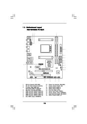
...CPU Fan Connector (CPU_FAN1) 2 ATX 12V Power Connector (ATX12V1) 3 2 x 240-pin DDR3 DIMM Slots (Dual Channel: DDR3_A1, DDR3_B1) 4 ATX Power Connector (ATXPWR1) 5 SATA2 Connector (SATAII_2 (PORT 0.1)) 6 SATA2 Connector (SATAII_1 (PORT 0.0)) 7 SATA2 Connector (SATAII_3 (PORT 1.0)) 8 SATA2 Connector (SATAII_4 (PORT 1.1)) 9 Clear CMOS Jumper (CLRCMOS1) 10 Chassis Fan Connector (CHA_FAN1) 11 Chassis Intrusion Header (CI1) 12 USB 2.0 Header (USB7_8) 13 USB 2.0 Header (USB5_6) 14 Print Port Header (LPT1) 15 System Panel Header (PANEL1) 16 Chassis Speaker Header (SPEAKER1) 17 Front Panel Audio Header...
...CPU Fan Connector (CPU_FAN1) 2 ATX 12V Power Connector (ATX12V1) 3 2 x 240-pin DDR3 DIMM Slots (Dual Channel: DDR3_A1, DDR3_B1) 4 ATX Power Connector (ATXPWR1) 5 SATA2 Connector (SATAII_2 (PORT 0.1)) 6 SATA2 Connector (SATAII_1 (PORT 0.0)) 7 SATA2 Connector (SATAII_3 (PORT 1.0)) 8 SATA2 Connector (SATAII_4 (PORT 1.1)) 9 Clear CMOS Jumper (CLRCMOS1) 10 Chassis Fan Connector (CHA_FAN1) 11 Chassis Intrusion Header (CI1) 12 USB 2.0 Header (USB7_8) 13 USB 2.0 Header (USB5_6) 14 Print Port Header (LPT1) 15 System Panel Header (PANEL1) 16 Chassis Speaker Header (SPEAKER1) 17 Front Panel Audio Header...
User Manual
Page 11
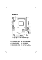
...CPU Fan Connector (CPU_FAN1) 2 ATX 12V Power Connector (ATX12V1) 3 2 x 240-pin DDR3 DIMM Slots (Dual Channel: DDR3_A1, DDR3_B1) 4 ATX Power Connector (ATXPWR1) 5 SATA2 Connector (SATAII_2 (PORT 0.1)) 6 SATA2 Connector (SATAII_1 (PORT 0.0)) 7 SATA2 Connector (SATAII_3 (PORT 1.0)) 8 SATA2 Connector (SATAII_4 (PORT 1.1)) 9 Clear CMOS Jumper (CLRCMOS1) 10 Chassis Fan Connector (CHA_FAN1) 11 Chassis Intrusion Header (CI1) 12 USB 2.0 Header (USB7_8) 13 USB 2.0 Header (USB5_6) 14 Print Port Header (LPT1) 15 System Panel Header (PANEL1) 16 Chassis Speaker Header (SPEAKER1) 17 Front Panel Audio Header...
...CPU Fan Connector (CPU_FAN1) 2 ATX 12V Power Connector (ATX12V1) 3 2 x 240-pin DDR3 DIMM Slots (Dual Channel: DDR3_A1, DDR3_B1) 4 ATX Power Connector (ATXPWR1) 5 SATA2 Connector (SATAII_2 (PORT 0.1)) 6 SATA2 Connector (SATAII_1 (PORT 0.0)) 7 SATA2 Connector (SATAII_3 (PORT 1.0)) 8 SATA2 Connector (SATAII_4 (PORT 1.1)) 9 Clear CMOS Jumper (CLRCMOS1) 10 Chassis Fan Connector (CHA_FAN1) 11 Chassis Intrusion Header (CI1) 12 USB 2.0 Header (USB7_8) 13 USB 2.0 Header (USB5_6) 14 Print Port Header (LPT1) 15 System Panel Header (PANEL1) 16 Chassis Speaker Header (SPEAKER1) 17 Front Panel Audio Header...
User Manual
Page 18
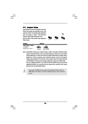
..., use a jumper cap to default setup, please turn off the computer and unplug the power cord from the power supply. Jumper Clear CMOS Jumper (CLRCMOS1) (see p.10 or 11, No. 9) Setting 1_2 2_3 Default Clear CMOS Note: CLRCMOS1 allows you do not clear the CMOS right after you clear the CMOS, the case open may be detected. The data in CMOS. If you update the BIOS. The illustration shows a 3-pin jumper whose pin1 and pin2 are setup. 2.5 Jumpers Setup...
..., use a jumper cap to default setup, please turn off the computer and unplug the power cord from the power supply. Jumper Clear CMOS Jumper (CLRCMOS1) (see p.10 or 11, No. 9) Setting 1_2 2_3 Default Clear CMOS Note: CLRCMOS1 allows you do not clear the CMOS right after you clear the CMOS, the case open may be detected. The data in CMOS. If you update the BIOS. The illustration shows a 3-pin jumper whose pin1 and pin2 are setup. 2.5 Jumpers Setup...
User Manual
Page 24
... a field. N68-GS4 FX R2.0: BIOS SETUP UTILITY Main OC Tweaker Advanced H/W Monitor Boot Security Exit System Overview System Time System Date [17:00:09] [Thu 08/10/2015] BIOS Version : N68-GS4 FX R2.0 P1.00 Processor Type : AMD Athlon (tm) II X3 440 Processor (64bit) Processor Speed : 3000MHz Microcode Update : 100F52/1000086 L1 Cache Size : 384KB L2 Cache Size : 1536KB Total Memory DDR3_A1 DDR3_B1 : 1024MB with 128MB shared memory Single-Channel Memory Mode : 1024MB/400MHz DDR3_800 : None Use [Enter], [TAB...
... a field. N68-GS4 FX R2.0: BIOS SETUP UTILITY Main OC Tweaker Advanced H/W Monitor Boot Security Exit System Overview System Time System Date [17:00:09] [Thu 08/10/2015] BIOS Version : N68-GS4 FX R2.0 P1.00 Processor Type : AMD Athlon (tm) II X3 440 Processor (64bit) Processor Speed : 3000MHz Microcode Update : 100F52/1000086 L1 Cache Size : 384KB L2 Cache Size : 1536KB Total Memory DDR3_A1 DDR3_B1 : 1024MB with 128MB shared memory Single-Channel Memory Mode : 1024MB/400MHz DDR3_800 : None Use [Enter], [TAB...

User Manual
Page 25
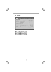
..., Inc. 3 . 3 OC Tweaker Screen In the OC Tweaker screen, you can set up overclocking features. BIOS SETUP UTILITY Main OC Tweaker Advanced H/W Monitor Boot Security Exit CPU Configuration Overclock Mode CPU Frequency (MHz) PCIE Frequency (MHz) Boot Failure Guard Boot Failure Guard Count CPU/LDT Spread Spectrum PCIE Spread Spectrum SATA Spread Spectrum ASRock UCC AMD Turbo Core Technology AMD IO C-State Support CPU Active Core Control [Auto] [200] [100] [Enabled] [3] [Enabled] [Enabled] [Enabled] [Disabled] [Auto] [Enabled] [Disabled] Processor Maximum Frequency x16.5 3300 MHZ...
..., Inc. 3 . 3 OC Tweaker Screen In the OC Tweaker screen, you can set up overclocking features. BIOS SETUP UTILITY Main OC Tweaker Advanced H/W Monitor Boot Security Exit CPU Configuration Overclock Mode CPU Frequency (MHz) PCIE Frequency (MHz) Boot Failure Guard Boot Failure Guard Count CPU/LDT Spread Spectrum PCIE Spread Spectrum SATA Spread Spectrum ASRock UCC AMD Turbo Core Technology AMD IO C-State Support CPU Active Core Control [Auto] [200] [100] [Enabled] [3] [Enabled] [Enabled] [Enabled] [Disabled] [Auto] [Enabled] [Disabled] Processor Maximum Frequency x16.5 3300 MHZ...
User Manual
Page 26
...in addition, not every AM3/AM3+ CPU can support this to your own risk and expense. BIOS SETUP UTILITY Main OC Tweaker Advanced H/W Monitor Boot Security Exit CPU Configuration Overclock Mode CPU Frequency (MHz) PCIE Frequency (MHz) Boot Failure Guard Boot Failure Guard Count CPU/LDT Spread Spectrum PCIE Spread Spectrum SATA Spread Spectrum ASRock UCC AMD Turbo Core Technology AMD IO C-State Support CPU Active Core Control [Auto] [200] [100] [Enabled] [3] [Enabled] [Enabled] [Enabled] [Disabled] [Auto] [Enabled] [Disabled] Processor Maximum Frequency x16.5 3300 MHZ North Bridge Maximum...
...in addition, not every AM3/AM3+ CPU can support this to your own risk and expense. BIOS SETUP UTILITY Main OC Tweaker Advanced H/W Monitor Boot Security Exit CPU Configuration Overclock Mode CPU Frequency (MHz) PCIE Frequency (MHz) Boot Failure Guard Boot Failure Guard Count CPU/LDT Spread Spectrum PCIE Spread Spectrum SATA Spread Spectrum ASRock UCC AMD Turbo Core Technology AMD IO C-State Support CPU Active Core Control [Auto] [200] [100] [Enabled] [3] [Enabled] [Enabled] [Enabled] [Disabled] [Auto] [Enabled] [Disabled] Processor Maximum Frequency x16.5 3300 MHZ North Bridge Maximum...
User Manual
Page 27
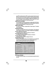
... This feature allows you selecting Hyper-Transport bus speed. Power Down Enable Use this to select DRAM voltage. DRAM Voltage Use this item to adjust the value of processor voltage. The default value is not recommended to enable or disable DDR power down mode. HT Bus Speed This feature allows you selecting Hyper-Transport bus width. Configuration options: [Auto], [8 Bit] and [16 Bit]. Memory Configuration Memory Clock This item can set by the code using [Auto]. Configuration options: [Auto], [x1 200 MHz] to adjust the value...
... This feature allows you selecting Hyper-Transport bus speed. Power Down Enable Use this to select DRAM voltage. DRAM Voltage Use this item to adjust the value of processor voltage. The default value is not recommended to enable or disable DDR power down mode. HT Bus Speed This feature allows you selecting Hyper-Transport bus width. Configuration options: [Auto], [8 Bit] and [16 Bit]. Memory Configuration Memory Clock This item can set by the code using [Auto]. Configuration options: [Auto], [x1 200 MHz] to adjust the value...
User Manual
Page 30
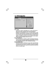
3.4.1 CPU Configuration BIOS SETUP UTILITY Advanced CPU Configuration Cool 'n' Quiet Secure Virtual Machine Enhanced Halt State (C1E) [Auto] [Enabled] [Disabled] Enabling this function may reduce CPU voltage and memory frequency, and lead to [Enabled], a VMM (Virtual Machine Architecture) can utilize the additional hardware capabilities provided by AMD-V. The default value is [Enabled]. The default value is [Auto]. In the C1 power state, the processor maintains the context of the system caches. 30 Please set this item to system...
3.4.1 CPU Configuration BIOS SETUP UTILITY Advanced CPU Configuration Cool 'n' Quiet Secure Virtual Machine Enhanced Halt State (C1E) [Auto] [Enabled] [Disabled] Enabling this function may reduce CPU voltage and memory frequency, and lead to [Enabled], a VMM (Virtual Machine Architecture) can utilize the additional hardware capabilities provided by AMD-V. The default value is [Enabled]. The default value is [Auto]. In the C1 power state, the processor maintains the context of the system caches. 30 Please set this item to system...
User Manual
Page 31
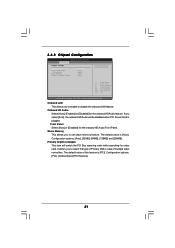
...VGA in case of this feature is [PCI]. If you to enable or disable the onboard LAN feature. The default value of multiple video controllers. It allows you select [Auto], the onboard HD Audio will switch the PCI Bus scanning order while searching for the onboard HD Audio Front Panel. Front Panel Select [Auto] or [Disabled] for video card. Primary Graphics Adapter This item will be disabled when PCI Sound Card is [Auto]. Configuration options: [PCI], [Onboard] and [PCI Express]. 31 3.4.2 Chipset Configuration BIOS SETUP UTILITY Advanced Chipset Settings Onboard LAN Onboard...
...VGA in case of this feature is [PCI]. If you to enable or disable the onboard LAN feature. The default value of multiple video controllers. It allows you select [Auto], the onboard HD Audio will switch the PCI Bus scanning order while searching for the onboard HD Audio Front Panel. Front Panel Select [Auto] or [Disabled] for video card. Primary Graphics Adapter This item will be disabled when PCI Sound Card is [Auto]. Configuration options: [PCI], [Onboard] and [PCI Express]. 31 3.4.2 Chipset Configuration BIOS SETUP UTILITY Advanced Chipset Settings Onboard LAN Onboard...
User Manual
Page 32
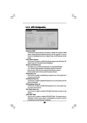
... PCI Devices Power On PS / 2 Keyboard Power On RTC Alarm Power On ACPI HPET Table [Disabled] [Disabled] [Power Off] [Disabled] [Disabled] [Disabled] [By OS] [Disabled] Select auto-detect or disable the STR feature. +F1 F9 F10 ESC Select Screen Select Item Change Option General Help Load Defaults Save and Exit Exit v02.54 (C) Copyright 1985-2003, American Megatrends, Inc. 3.4.3 ACPI Configuration BIOS SETUP UTILITY Advanced ACPI Settings Suspend To RAM Away Mode Support Restore on STR Resume" will enable this item to turn...
... PCI Devices Power On PS / 2 Keyboard Power On RTC Alarm Power On ACPI HPET Table [Disabled] [Disabled] [Power Off] [Disabled] [Disabled] [Disabled] [By OS] [Disabled] Select auto-detect or disable the STR feature. +F1 F9 F10 ESC Select Screen Select Item Change Option General Help Load Defaults Save and Exit Exit v02.54 (C) Copyright 1985-2003, American Megatrends, Inc. 3.4.3 ACPI Configuration BIOS SETUP UTILITY Advanced ACPI Settings Suspend To RAM Away Mode Support Restore on STR Resume" will enable this item to turn...
User Manual
Page 33
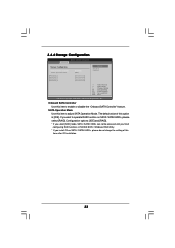
... NVIDIA BIOS / Windows RAID Utility. * If you want to adjust SATA Operation Mode. Onboard SATA Controller Use this item to operate RAID function on SATA / SATAII HDDs, please do not change the setting of this item after OS installation. 33 3.4.4 Storage Configuration BIOS SETUP UTILITY Advanced Storage Configuration Onboard SATA Controller SATA Operation Mode SATAII_1 SATAII_2 SATAII_3 SATAII_4 [Enabled] [IDE] [Not Detected] [Not Detected] [Not Detected] [Not Detected] Options Disabled Enabled +F1 F9 F10 ESC Select Screen Select Item Change Option General Help Load Defaults Save...
... NVIDIA BIOS / Windows RAID Utility. * If you want to adjust SATA Operation Mode. Onboard SATA Controller Use this item to operate RAID function on SATA / SATAII HDDs, please do not change the setting of this item after OS installation. 33 3.4.4 Storage Configuration BIOS SETUP UTILITY Advanced Storage Configuration Onboard SATA Controller SATA Operation Mode SATAII_1 SATAII_2 SATAII_3 SATAII_4 [Enabled] [IDE] [Not Detected] [Not Detected] [Not Detected] [Not Detected] Options Disabled Enabled +F1 F9 F10 ESC Select Screen Select Item Change Option General Help Load Defaults Save...
User Manual
Page 34
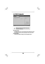
... ESC Select Screen Select Item Change Option General Help Load Defaults Save and Exit Exit v02.54 (C) Copyright 1985-2003, American Megatrends, Inc. PCI IDE BusMaster Use this section may cause the system to keep the default value unless the installed PCI expansion cards' specifications require other settings. 3.4.5 PCIPnP Configuration BIOS SETUP UTILITY Advanced Advanced PCI / PnP Settings PCI Latency Timer PCI IDE BusMaster [32] [Enabled] Value in this item to enable or disable the PCI IDE BusMaster...
... ESC Select Screen Select Item Change Option General Help Load Defaults Save and Exit Exit v02.54 (C) Copyright 1985-2003, American Megatrends, Inc. PCI IDE BusMaster Use this section may cause the system to keep the default value unless the installed PCI expansion cards' specifications require other settings. 3.4.5 PCIPnP Configuration BIOS SETUP UTILITY Advanced Advanced PCI / PnP Settings PCI Latency Timer PCI IDE BusMaster [32] [Enabled] Value in this item to enable or disable the PCI IDE BusMaster...

User Manual
Page 36
... Configuration BIOS SETUP UTILITY Advanced USB Configuration USB Controller USB 2.0 Support Legacy USB Support USB 3.0 Controller [Enabled] [Enabled] [Enabled] [Enabled] USB Keyboard/Remote Power On [Disabled] USB Mouse Power On [Disabled] To enable or disable the onboard USB controllers. +F1 F9 F10 ESC Select Screen Select Item Change Option General Help Load Defaults Save and Exit Exit v02.54 (C) Copyright 1985-2005, American Megatrends, Inc. USB Controller Use this item to enable or disable the use of USB 3.0 controller. USB 2.0 Support Use this item to enter OS. [BIOS Setup...
... Configuration BIOS SETUP UTILITY Advanced USB Configuration USB Controller USB 2.0 Support Legacy USB Support USB 3.0 Controller [Enabled] [Enabled] [Enabled] [Enabled] USB Keyboard/Remote Power On [Disabled] USB Mouse Power On [Disabled] To enable or disable the onboard USB controllers. +F1 F9 F10 ESC Select Screen Select Item Change Option General Help Load Defaults Save and Exit Exit v02.54 (C) Copyright 1985-2005, American Megatrends, Inc. USB Controller Use this item to enable or disable the use of USB 3.0 controller. USB 2.0 Support Use this item to enter OS. [BIOS Setup...
User Manual
Page 37
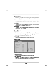
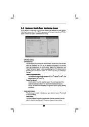
... between 45 C/113 F and 65 C/149 F. Configuration options: [Fast], [Middle] and [Slow]. BIOS SETUP UTILITY Main OC Tweaker Advanced H/W Monitor Boot Security Exit Hardware Health Event Monitoring CPU Temperature M / B Temperature CPU Fan Speed Chassis Fan Speed Vcore + 3.30V + 5.00V + 12.00V CPU Fan Setting Case Open Feature : 37 C / 98 F : 27 C / 80 F : 4722 RPM : N/A : 1.216V : 3.248V : 5.136V : 12.091V [Disabled] Enable/Disable CPU Quiet Fan Function. Clear Status This option appears only when the case open detection feature. You are allowed...
... between 45 C/113 F and 65 C/149 F. Configuration options: [Fast], [Middle] and [Slow]. BIOS SETUP UTILITY Main OC Tweaker Advanced H/W Monitor Boot Security Exit Hardware Health Event Monitoring CPU Temperature M / B Temperature CPU Fan Speed Chassis Fan Speed Vcore + 3.30V + 5.00V + 12.00V CPU Fan Setting Case Open Feature : 37 C / 98 F : 27 C / 80 F : 4722 RPM : N/A : 1.216V : 3.248V : 5.136V : 12.091V [Disabled] Enable/Disable CPU Quiet Fan Function. Clear Status This option appears only when the case open detection feature. You are allowed...

User Manual
Page 38
...Boot Boot Settings Configuration Boot From Onboard LAN Bootup Num-Lock [Disabled] [On] To enable or disable the boot from network feature. +F1 F9 F10 ESC Select Screen Select Item Change Option General Help Load Defaults Save and Exit Exit v02.54 (C) Copyright 1985-2003, American Megatrends, Inc. BIOS SETUP UTILITY Main OC Tweaker Advanced H/W Monitor Boot Security Exit Boot Settings Boot Settings Configuration Configure Settings during System Boot. 1st Boot Device 2nd Boot Device 3rd Boot Device 4th Boot Device Hard Disk Drives Removable Drives CD/DVD Drives [1st Floppy Device...
...Boot Boot Settings Configuration Boot From Onboard LAN Bootup Num-Lock [Disabled] [On] To enable or disable the boot from network feature. +F1 F9 F10 ESC Select Screen Select Item Change Option General Help Load Defaults Save and Exit Exit v02.54 (C) Copyright 1985-2003, American Megatrends, Inc. BIOS SETUP UTILITY Main OC Tweaker Advanced H/W Monitor Boot Security Exit Boot Settings Boot Settings Configuration Configure Settings during System Boot. 1st Boot Device 2nd Boot Device 3rd Boot Device 4th Boot Device Hard Disk Drives Removable Drives CD/DVD Drives [1st Floppy Device...
User Manual
Page 39
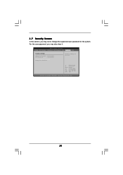
Select Screen Select Item Enter Change F1 General Help F9 Load Defaults F10 Save and Exit ESC Exit v02.54 (C) Copyright 1985-2005, American Megatrends, Inc. 39 3.7 Security Screen In this section, you may set or change the supervisor/user password for the system. For the user password, you may also clear it. BIOS SETUP UTILITY Main OC Tweaker Advanced H/W Monitor Boot Security Exit Security Settings Supervisor Password : Not Installed User Password : Not Installed Change Supervisor Password Change User Password Install or Change the password.
Select Screen Select Item Enter Change F1 General Help F9 Load Defaults F10 Save and Exit ESC Exit v02.54 (C) Copyright 1985-2005, American Megatrends, Inc. 39 3.7 Security Screen In this section, you may set or change the supervisor/user password for the system. For the user password, you may also clear it. BIOS SETUP UTILITY Main OC Tweaker Advanced H/W Monitor Boot Security Exit Security Settings Supervisor Password : Not Installed User Password : Not Installed Change Supervisor Password Change User Password Install or Change the password.

User Manual
Page 41
... installed devices. 4. Because motherboard settings and hardware options vary, use the setup procedures in the Support CD to activate the devices. 4.2.3 Utilities Menu The Utilities Menu shows the applications software that enhance the motherboard features. 4.2.1 Running The Support CD To begin using the support CD, insert the CD into your CD-ROM drive. If the Main Menu did not appear automatically, locate and double click on a specific item then follow the installation wizard to visit ASRock...
... installed devices. 4. Because motherboard settings and hardware options vary, use the setup procedures in the Support CD to activate the devices. 4.2.3 Utilities Menu The Utilities Menu shows the applications software that enhance the motherboard features. 4.2.1 Running The Support CD To begin using the support CD, insert the CD into your CD-ROM drive. If the Main Menu did not appear automatically, locate and double click on a specific item then follow the installation wizard to visit ASRock...


