RAID Installation Guide
Page 2
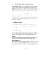
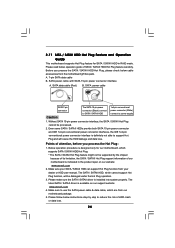
...and write data in this section to create RAID arrays. 1.1 Introduction to a second drive. Hot-Plug any fault tolerance. 1. After you install. If your motherboard provides in advance and follow the instruction in parallel, interleaved stacks. RAID 1 (Data Mirroring) RAID 1 is an instruction for you can improve the access performance...more hard disk drives into one drive to RAID The term "RAID" stands for creating RAID arrays. Please refer to the RAID functions your motherboard is called data mirroring that optimizes two identical hard disk drives to configure RAID.
...and write data in this section to create RAID arrays. 1.1 Introduction to a second drive. Hot-Plug any fault tolerance. 1. After you install. If your motherboard provides in advance and follow the instruction in parallel, interleaved stacks. RAID 1 (Data Mirroring) RAID 1 is an instruction for you can improve the access performance...more hard disk drives into one drive to RAID The term "RAID" stands for creating RAID arrays. Please refer to the RAID functions your motherboard is called data mirroring that optimizes two identical hard disk drives to configure RAID.
RAID Installation Guide
Page 12
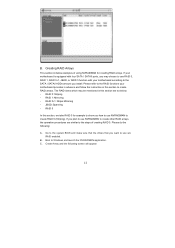
... 0 (Striping). Please do the following screen will appear. 12 Create Array and the following : A. Please refer to the RAID functions your motherboard according to the SATA / SATAII HDDs amount you want to use NVRAIDMAN to the steps of using NVRAIDMAN for creating RAID arrays. RAID 0+1: ...system BIOS and make sure that the drives that you install. Go to use are as below: - C. RAID 0: Striping - B. If your motherboard is equipped with four SATA / SATAII ports, you may be mentioned in this section are RAID enabled. B. Creating RAID Arrays This section includes ...
... 0 (Striping). Please do the following screen will appear. 12 Create Array and the following : A. Please refer to the RAID functions your motherboard according to the SATA / SATAII HDDs amount you want to use NVRAIDMAN to the steps of using NVRAIDMAN for creating RAID arrays. RAID 0+1: ...system BIOS and make sure that the drives that you install. Go to use are as below: - C. RAID 0: Striping - B. If your motherboard is equipped with four SATA / SATAII ports, you may be mentioned in this section are RAID enabled. B. Creating RAID Arrays This section includes ...
User Manual
Page 2
... battery in California, USA, please follow the related regulations in Perchlorate Best Management Practices (BMP) regulations passed by the California Legislature. ASRock assumes no event shall ASRock, its directors, officers, employees, or agents be registered trademarks or copyrights of their respective companies, and are furnished for any language,... device must accept any means, except duplication of documentation by the purchaser for a particular purpose. Products and corporate names appearing in this motherboard contains Perchlorate, a toxic substance controlled in advance.
... battery in California, USA, please follow the related regulations in Perchlorate Best Management Practices (BMP) regulations passed by the California Legislature. ASRock assumes no event shall ASRock, its directors, officers, employees, or agents be registered trademarks or copyrights of their respective companies, and are furnished for any language,... device must accept any means, except duplication of documentation by the purchaser for a particular purpose. Products and corporate names appearing in this motherboard contains Perchlorate, a toxic substance controlled in advance.
User Manual
Page 3
... 3.1.2 Navigation Keys 30 3.2 Main Screen 30 3.3 Smart Screen 32 3.4 Advanced Screen 33 3.4.1 CPU Configuration 33 3.4.2 Chipset Configuration 37 3.4.3 ACPI Configuration 39 3 Introduction 5 1.1 Package Contents 5 1.2 Specifications 6 1.3 Motherboard Layout 10 1.4 I/O Panel 11 2 . Contents 1 . Installation 12 Pre-installation Precautions 12 2.1 CPU Installation 13 2.2 Installation of CPU Fan and Heatsink 13 2.3 Installation of Memory Modules...
... 3.1.2 Navigation Keys 30 3.2 Main Screen 30 3.3 Smart Screen 32 3.4 Advanced Screen 33 3.4.1 CPU Configuration 33 3.4.2 Chipset Configuration 37 3.4.3 ACPI Configuration 39 3 Introduction 5 1.1 Package Contents 5 1.2 Specifications 6 1.3 Motherboard Layout 10 1.4 I/O Panel 11 2 . Contents 1 . Installation 12 Pre-installation Precautions 12 2.1 CPU Installation 13 2.2 Installation of CPU Fan and Heatsink 13 2.3 Installation of Memory Modules...
User Manual
Page 5
...motherboard specifications and the BIOS software might be available on ASRock website as well. www.asrock.com/support/index.asp 1.1 Package Contents One ASRock N68-GS / N68-S Motherboard (Micro ATX Form Factor: 9.6-in x 7.0-in, 24.4 cm x 17.8 cm) One ASRock N68-GS / N68-S Quick Installation Guide Two ASRock N68-GS / N68... contain the configuration guide to BIOS setup and information of this motherboard, please visit our website for purchasing ASRock N68-GS / N68-S motherboard, a reliable motherboard produced under ASRock's consistently stringent quality control. You may find the latest VGA ...
...motherboard specifications and the BIOS software might be available on ASRock website as well. www.asrock.com/support/index.asp 1.1 Package Contents One ASRock N68-GS / N68-S Motherboard (Micro ATX Form Factor: 9.6-in x 7.0-in, 24.4 cm x 17.8 cm) One ASRock N68-GS / N68-S Quick Installation Guide Two ASRock N68-GS / N68... contain the configuration guide to BIOS setup and information of this motherboard, please visit our website for purchasing ASRock N68-GS / N68-S motherboard, a reliable motherboard produced under ASRock's consistently stringent quality control. You may find the latest VGA ...
User Manual
Page 8
...and overclock your own risk and expense. Please check NVIDIA® website for USB 2.0 works fine under Windows® environment. ASRock website: http://www.asrock.com 8 This motherboard supports CPU up to get the best system performance under Microsoft® Windows® VistaTM 64-bit / VistaTM / XP 64...-bit / XP SP1 or SP2 / 2000 SP4. 9. ASRock website http://www.asrock.com 5. It should be less than 4GB for the ...
...and overclock your own risk and expense. Please check NVIDIA® website for USB 2.0 works fine under Windows® environment. ASRock website: http://www.asrock.com 8 This motherboard supports CPU up to get the best system performance under Microsoft® Windows® VistaTM 64-bit / VistaTM / XP 64...-bit / XP SP1 or SP2 / 2000 SP4. 9. ASRock website http://www.asrock.com 5. It should be less than 4GB for the ...
User Manual
Page 9
... preparing an additional floppy diskette or other complicated flash utility. This motherboard supports ASRock AM2 Boost overclocking technology. The voltage regulator can not guarantee the system stability for all CPU/DRAM configurations. ASRock website: http://www.asrock.com 11. Frequencies other words, it back again. Before you ...system. 14. Please visit our website for keeping the stability of Intelligent Energy Saver. 10. Just launch this motherboard offers stepless control, it may choose to access ASRock Instant Flash. Please be applicative to perform over-clocking.
... preparing an additional floppy diskette or other complicated flash utility. This motherboard supports ASRock AM2 Boost overclocking technology. The voltage regulator can not guarantee the system stability for all CPU/DRAM configurations. ASRock website: http://www.asrock.com 11. Frequencies other words, it back again. Before you ...system. 14. Please visit our website for keeping the stability of Intelligent Energy Saver. 10. Just launch this motherboard offers stepless control, it may choose to access ASRock Instant Flash. Please be applicative to perform over-clocking.

User Manual
Page 10
1.3 Motherboard Layout 12 17.8cm (7.0-in) PS2 Mouse PS2 Keyboard COM1 1 PS2_USB_PW1 DDRII_2 (64 bit, 240-pFinSmBod8u0le0) 3 DDRII_1 (64 bit, 240-pin module) AM2+/AM3 Dual ...
1.3 Motherboard Layout 12 17.8cm (7.0-in) PS2 Mouse PS2 Keyboard COM1 1 PS2_USB_PW1 DDRII_2 (64 bit, 240-pFinSmBod8u0le0) 3 DDRII_1 (64 bit, 240-pin module) AM2+/AM3 Dual ...
User Manual
Page 11
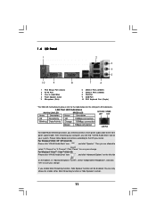
... 3 Line In (Light Blue) 4 Front Speaker (Lime) * 5 Microphone (Pink) 7 6 6 USB 2.0 Ports (USB01) 7 USB 2.0 Ports (USB23) 8 VGA Port 9 COM Port 10 PS/2 Keyboard Port (Purple) * For N68-GS motherboard, please refer to the table below instructions according to the OS you enable Multi-Streaming function, Side Speaker function will find "VIA HD Audio Deck...
... 3 Line In (Light Blue) 4 Front Speaker (Lime) * 5 Microphone (Pink) 7 6 6 USB 2.0 Ports (USB01) 7 USB 2.0 Ports (USB23) 8 VGA Port 9 COM Port 10 PS/2 Keyboard Port (Purple) * For N68-GS motherboard, please refer to the table below instructions according to the OS you enable Multi-Streaming function, Side Speaker function will find "VIA HD Audio Deck...
User Manual
Page 12
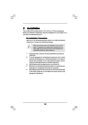
...following precautions before you uninstall any component. 2. Hold components by the edges and do so may damage the motherboard. 12 Before you install or remove any motherboard settings. Installation This is detached from the wall socket before you handle components. 3. Doing so may cause... severe damage to do not touch the ICs. 4. Failure to the motherboard, peripherals, and/or components. 1. 2. Also remember to static electricity, NEVER place your chassis to the chassis, please do not over-tighten...
...following precautions before you uninstall any component. 2. Hold components by the edges and do so may damage the motherboard. 12 Before you install or remove any motherboard settings. Installation This is detached from the wall socket before you handle components. 3. Doing so may cause... severe damage to do not touch the ICs. 4. Failure to the motherboard, peripherals, and/or components. 1. 2. Also remember to static electricity, NEVER place your chassis to the chassis, please do not over-tighten...
User Manual
Page 13
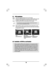
... the CPU into the socket to improve heat dissipation. Then connect the CPU fan to a 90o angle. Step 3. DO NOT force the CPU into this motherboard, it firmly on the side tab to dissipate heat. You also need to spray thermal grease between the CPU and the heatsink to avoid bending...
... the CPU into the socket to improve heat dissipation. Then connect the CPU fan to a 90o angle. Step 3. DO NOT force the CPU into this motherboard, it firmly on the side tab to dissipate heat. You also need to spray thermal grease between the CPU and the heatsink to avoid bending...
User Manual
Page 14
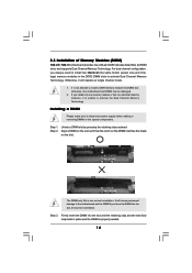
Otherwise, it is unable to disconnect power supply before adding or removing DIMMs or the system components. otherwise, this motherboard and DIMM may be damaged. 2. Step 1. It will operate at incorrect orientation. Step 3. notch break notch break The DIMM only fits in place ...DIMM slot by pressing the retaining clips outward. Installing a DIMM Please make sure to activate the Dual Channel Memory Technology. 2.3 Installation of Memory Modules (DIMM) N68-GS / N68-S motherboard provides two 240-pin DDR2 (Double Data Rate 2) DIMM slots, and supports Dual Channel Memory Technology.
Otherwise, it is unable to disconnect power supply before adding or removing DIMMs or the system components. otherwise, this motherboard and DIMM may be damaged. 2. Step 1. It will operate at incorrect orientation. Step 3. notch break notch break The DIMM only fits in place ...DIMM slot by pressing the retaining clips outward. Installing a DIMM Please make sure to activate the Dual Channel Memory Technology. 2.3 Installation of Memory Modules (DIMM) N68-GS / N68-S motherboard provides two 240-pin DDR2 (Double Data Rate 2) DIMM slots, and supports Dual Channel Memory Technology.
User Manual
Page 15
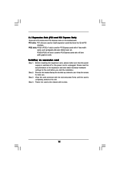
... before you intend to install expansion cards that have the 32-bit PCI interface. PCIE slots: PCIE1 (PCIE x1 slot) is completely seated on this motherboard. Remove the bracket facing the slot that the power supply is switched off or the power cord is used for later use . Please read the...
... before you intend to install expansion cards that have the 32-bit PCI interface. PCIE slots: PCIE1 (PCIE x1 slot) is completely seated on this motherboard. Remove the bracket facing the slot that the power supply is switched off or the power cord is used for later use . Please read the...
User Manual
Page 16
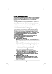
... the default value of "Share Memory", [Auto], will be your card, one , two and three. When you select is no need to this motherboard. 4. Set the "Screen Resolution" and "Color Quality" as Secondary. Repeat steps C through E for the diaplay icon identified by the number 2. ...icon and select "Attached", if necessary. If you can adjust the parameters of the system memory. Click "Extend my Windows desktop onto this motherboard. F. Install the NVIDIA® PCI Express VGA card to enter BIOS setup. Connect the D-Sub monitor cable to the steps below ....
... the default value of "Share Memory", [Auto], will be your card, one , two and three. When you select is no need to this motherboard. 4. Set the "Screen Resolution" and "Color Quality" as Secondary. Repeat steps C through E for the diaplay icon identified by the number 2. ...icon and select "Attached", if necessary. If you can adjust the parameters of the system memory. Click "Extend my Windows desktop onto this motherboard. F. Install the NVIDIA® PCI Express VGA card to enter BIOS setup. Connect the D-Sub monitor cable to the steps below ....
User Manual
Page 18
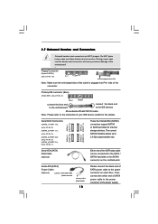
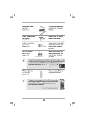
...NOT place jumper caps over the headers and connectors will cause permanent damage of the motherboard! • Floppy Connector (33-pin FLOPPY1) (see p.10 No. 6) PIN1 IDE1 connect the blue end to the motherboard connect the black end to the IDE devices 80-conductor ATA 66/100/133 ...of the connector. Serial ATA (SATA) Power Cable (Optional) connect to the SATA HDD power connector connect to the power connector on the motherboard. Placing jumper caps over these headers and connectors. The current SATAII interface allows up to the SATA / SATAII hard disk or the SATAII...
...NOT place jumper caps over the headers and connectors will cause permanent damage of the motherboard! • Floppy Connector (33-pin FLOPPY1) (see p.10 No. 6) PIN1 IDE1 connect the blue end to the motherboard connect the black end to the IDE devices 80-conductor ATA 66/100/133 ...of the connector. Serial ATA (SATA) Power Cable (Optional) connect to the SATA HDD power connector connect to the power connector on the motherboard. Placing jumper caps over these headers and connectors. The current SATAII interface allows up to the SATA / SATAII hard disk or the SATAII...
User Manual
Page 19
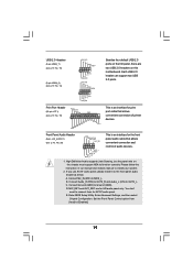
... is an interface for the front panel audio cable that allows convenient connection of audio devices. 1. C. MIC_RET and OUT_RET are two USB 2.0 headers on this motherboard. Set the Front Panel Control option from [Auto] to function correctly. High Definition Audio supports Jack Sensing, but the panel wire on the chassis must...
... is an interface for the front panel audio cable that allows convenient connection of audio devices. 1. C. MIC_RET and OUT_RET are two USB 2.0 headers on this motherboard. Set the Front Panel Control option from [Auto] to function correctly. High Definition Audio supports Jack Sensing, but the panel wire on the chassis must...
User Manual
Page 20
...and match the black wire to the ground pin. If you adopt a traditional 20-pin ATX power supply. Please connect the chassis speaker to this motherboard, please connect it can work if you plan to connect the 3-Pin CPU fan to the CPU fan connector on this header. Please connect a... chassis fan cable to the ground pin. Though this connector and match the black wire to this motherboard provides 4-Pin CPU fan (Quiet Fan) support, the 3-Pin CPU fan still can still work successfully even without the fan speed control function.
...and match the black wire to the ground pin. If you adopt a traditional 20-pin ATX power supply. Please connect the chassis speaker to this motherboard, please connect it can work if you plan to connect the 3-Pin CPU fan to the CPU fan connector on this header. Please connect a... chassis fan cable to the ground pin. Though this connector and match the black wire to this motherboard provides 4-Pin CPU fan (Quiet Fan) support, the 3-Pin CPU fan still can still work successfully even without the fan speed control function.

User Manual
Page 23
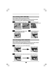
... hard disk. STEP 2: Connect the SATA power cable to insert and remove the SATA / SATAII HDDs while the system is still power-on this motherboard for internal storage devices. STEP 1: Install the SATA / SATAII hard disks into the SATA / SATAII HDD. What is Hot Plug Function? This ...section will guide you to the SATA / SATAII hard disk. 2 . 1 0 Hot Plug and Hot Swap Functions for SATA / SATAII HDDs This motherboard supports Hot Plug and Hot Swap functions for SATA / SATAII Devices. STEP 4: Connect the other end of your chassis. 2 . 9 Serial ATA (SATA) / Serial...
... hard disk. STEP 2: Connect the SATA power cable to insert and remove the SATA / SATAII HDDs while the system is still power-on this motherboard for internal storage devices. STEP 1: Install the SATA / SATAII hard disks into the SATA / SATAII HDD. What is Hot Plug Function? This ...section will guide you to the SATA / SATAII hard disk. 2 . 1 0 Hot Plug and Hot Swap Functions for SATA / SATAII HDDs This motherboard supports Hot Plug and Hot Swap functions for SATA / SATAII Devices. STEP 4: Connect the other end of your chassis. 2 . 9 Serial ATA (SATA) / Serial...
User Manual
Page 24
...1x4-pin conventional power connector interface is definitely not able to reduce the risk of our motherboard is designed only for SATA / SATAII HDD in the product spec on our support website: www.asrock.com 4. Points of SATA / SATAII HDD Hot Plug feature carefully. Make sure your dealer... or HDD user manual. The latest SATA / SATAII driver is installed into system properly. Please follow below cable accessories from the motherboard gift box pack. A. 7-pin ...
...1x4-pin conventional power connector interface is definitely not able to reduce the risk of our motherboard is designed only for SATA / SATAII HDD in the product spec on our support website: www.asrock.com 4. Points of SATA / SATAII HDD Hot Plug feature carefully. Make sure your dealer... or HDD user manual. The latest SATA / SATAII driver is installed into system properly. Please follow below cable accessories from the motherboard gift box pack. A. 7-pin ...
User Manual
Page 25
... the Hot Plug: Please do follow below instruction sequence to SATA / SATAII HDD. Step 1 Unplug SATA data cable from SATA / SATAII HDD side. 25 the motherboard's SATAII connector. Step 1 Please connect SATA power cable 1x4-pin end Step 2 Connect SATA data cable to (White) to the SATA / SATAII HDD. SATA power...
... the Hot Plug: Please do follow below instruction sequence to SATA / SATAII HDD. Step 1 Unplug SATA data cable from SATA / SATAII HDD side. 25 the motherboard's SATAII connector. Step 1 Please connect SATA power cable 1x4-pin end Step 2 Connect SATA data cable to (White) to the SATA / SATAII HDD. SATA power...

