

User Manual
Page 2
... translated in any language, in this documentation may or may apply, see www.dtsc.ca.gov/hazardouswaste/ perchlorate" ASRock Website: http://www.asrock.com When you discard the Lithium battery in California, USA, please follow the related regulations in Perchlorate Best Management ... of data, interruption of business and the like), even if ASRock has been advised of the possibility of documentation by the California Legislature. CALIFORNIA, USA ONLY he Lithium battery adopted on this motherboard contains Perchlorate, a toxic substance controlled in advance. Version 1.0 ...
... translated in any language, in this documentation may or may apply, see www.dtsc.ca.gov/hazardouswaste/ perchlorate" ASRock Website: http://www.asrock.com When you discard the Lithium battery in California, USA, please follow the related regulations in Perchlorate Best Management ... of data, interruption of business and the like), even if ASRock has been advised of the possibility of documentation by the California Legislature. CALIFORNIA, USA ONLY he Lithium battery adopted on this motherboard contains Perchlorate, a toxic substance controlled in advance. Version 1.0 ...

User Manual
Page 4
Contents Chapter 1 Introduction 1 1.1 Package Contents 1 1.2 Speciications 2 1.3 Motherboard Layout 5 1.4 I/O Panel 7 Chapter 2 Installation 9 2.1 Installing Memory Modules (DIMM) 10 2.2 Expansion Slots (PCI Express Slots) 12 2.3 Jumpers Setup 13 2.4 Onboard Headers and Connectors 14 Chapter 3 Software and Utilities Operation 18 3.1 Installing Drivers 18 3.2 ASRock APP Shop 19 3.2.1 UI Overview 19 3.2.2 Apps 20 3.2.3 BIOS & Drivers 23 3.2.4 Setting 24...
Contents Chapter 1 Introduction 1 1.1 Package Contents 1 1.2 Speciications 2 1.3 Motherboard Layout 5 1.4 I/O Panel 7 Chapter 2 Installation 9 2.1 Installing Memory Modules (DIMM) 10 2.2 Expansion Slots (PCI Express Slots) 12 2.3 Jumpers Setup 13 2.4 Onboard Headers and Connectors 14 Chapter 3 Software and Utilities Operation 18 3.1 Installing Drivers 18 3.2 ASRock APP Shop 19 3.2.1 UI Overview 19 3.2.2 Apps 20 3.2.3 BIOS & Drivers 23 3.2.4 Setting 24...
User Manual
Page 6
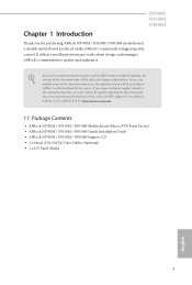
... coniguration guide of this manual, Chapter 1 and 2 contains the introduction of the motherboard and step-by-step installation guides. ASRock website http://www.asrock.com. 1.1 Package Contents • ASRock N3700M / N3150M / N3050M Motherboard (Micro ATX Form Factor) • ASRock N3700M / N3150M / N3050M Quick Installation Guide • ASRock N3700M / N3150M / N3050M Support CD • 2 x Serial ATA (SATA) Data Cables (Optional) •...
... coniguration guide of this manual, Chapter 1 and 2 contains the introduction of the motherboard and step-by-step installation guides. ASRock website http://www.asrock.com. 1.1 Package Contents • ASRock N3700M / N3150M / N3050M Motherboard (Micro ATX Form Factor) • ASRock N3700M / N3150M / N3050M Quick Installation Guide • ASRock N3700M / N3150M / N3050M Support CD • 2 x Serial ATA (SATA) Data Cables (Optional) •...

User Manual
Page 10
1.3 Motherboard Layout PS2 Mouse PS2 Keyboard USB3_2_3 USB_45 1 CPU_FAN1 VGA1 DDR3_B1 (64 bit, 240-pin module) DDR3_A1 (64 bit, 240-pin module) DVI1 Top: LINE IN Center: FRONT Bottom: MIC IN HDMI1 USB 3.0 T: USB0 B: USB1 USB 2.0 T: USB0 Top: RJ-45 B: USB1 LAN AUDIO CODEC CI1 1 HD_AUDIO1 TPMS1 1 1 AT X P W R 1 Front USB 3.0 RoHS 64Mb BIOS SATA3_1 PCIE1 SATA3_2 PCIE2 PCIE3 COM2 1 COM1 1 Super I/O LPT1 1 CMOS Battery SPEAKER1 1 1 1 USB_23 PLED PWRBTN 1 HDLED RESET PANEL1 CLRMOS1 5 English
1.3 Motherboard Layout PS2 Mouse PS2 Keyboard USB3_2_3 USB_45 1 CPU_FAN1 VGA1 DDR3_B1 (64 bit, 240-pin module) DDR3_A1 (64 bit, 240-pin module) DVI1 Top: LINE IN Center: FRONT Bottom: MIC IN HDMI1 USB 3.0 T: USB0 B: USB1 USB 2.0 T: USB0 Top: RJ-45 B: USB1 LAN AUDIO CODEC CI1 1 HD_AUDIO1 TPMS1 1 1 AT X P W R 1 Front USB 3.0 RoHS 64Mb BIOS SATA3_1 PCIE1 SATA3_2 PCIE2 PCIE3 COM2 1 COM1 1 Super I/O LPT1 1 CMOS Battery SPEAKER1 1 1 1 USB_23 PLED PWRBTN 1 HDLED RESET PANEL1 CLRMOS1 5 English

User Manual
Page 14
... object before installing or removing the motherboard. Chapter 2 Installation his is a Micro ATX form factor motherboard. Failure to the chassis, please do so may damage the motherboard. 9 English Doing so may cause physical injuries to you install motherboard components or change any components, place...components. • When placing screws to secure the motherboard to do not overtighten the screws! Before you install the motherboard, study the coniguration of the following precautions before you and damages to motherboard components. • In order to avoid damage from...
... object before installing or removing the motherboard. Chapter 2 Installation his is a Micro ATX form factor motherboard. Failure to the chassis, please do so may damage the motherboard. 9 English Doing so may cause physical injuries to you install motherboard components or change any components, place...components. • When placing screws to secure the motherboard to do not overtighten the screws! Before you install the motherboard, study the coniguration of the following precautions before you and damages to motherboard components. • In order to avoid damage from...

User Manual
Page 15
If only one correct orientation. he DIMM only its in one DIMM module is not allowed to the motherboard and the DIMM if you force the DIMM into DDR3_A1. It is installed, please install it into the slot at incorrect orientation. It will cause permanent damage to install a DDR or DDR2 memory module into a DDR3/DDR3L slot; 2.1 Installing Memory Modules (DIMM) N3700M N3150M N3050M his motherboard provides two 204-pin DDR3/DDR3L (Double Data Rate 3) DIMM slots. English 10 otherwise, this motherboard and DIMM may be damaged.
If only one correct orientation. he DIMM only its in one DIMM module is not allowed to the motherboard and the DIMM if you force the DIMM into DDR3_A1. It is installed, please install it into the slot at incorrect orientation. It will cause permanent damage to install a DDR or DDR2 memory module into a DDR3/DDR3L slot; 2.1 Installing Memory Modules (DIMM) N3700M N3150M N3050M his motherboard provides two 204-pin DDR3/DDR3L (Double Data Rate 3) DIMM slots. English 10 otherwise, this motherboard and DIMM may be damaged.
User Manual
Page 17
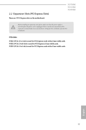
... width cards. PCIe slots: PCIE1 (PCIe 2.0 x1 slot) is unplugged. PCIE3 (PCIe 2.0 x1 slot) is used for the card before you start the installation. N3700M N3150M N3050M Before installing an expansion card, please make necessary hardware settings for PCI Express cards with x1 lane width cards. 2.2 Expansion Slots (PCI Express Slots...
... width cards. PCIe slots: PCIE1 (PCIe 2.0 x1 slot) is unplugged. PCIE3 (PCIe 2.0 x1 slot) is used for the card before you start the installation. N3700M N3150M N3050M Before installing an expansion card, please make necessary hardware settings for PCI Express cards with x1 lane width cards. 2.2 Expansion Slots (PCI Express Slots...

User Manual
Page 19
...freezes and fails to the reset switch on the chassis front panel. he LED is of (S5). he LED is on the chassis to the motherboard. When connecting your system using the power switch. System Panel Header (9-pin PANEL1) (see p.5, No. 9) PLED+ PLEDPWRBTN# GND 1 GND ...mainly consists of your chassis front panel module to this header according to the pin assignments below. 2.4 Onboard Headers and Connectors N3700M N3150M N3050M Onboard headers and connectors are matched correctly. Placing jumper caps over these headers and connectors. he front panel design may conigure the...
...freezes and fails to the reset switch on the chassis front panel. he LED is of (S5). he LED is on the chassis to the motherboard. When connecting your system using the power switch. System Panel Header (9-pin PANEL1) (see p.5, No. 9) PLED+ PLEDPWRBTN# GND 1 GND ...mainly consists of your chassis front panel module to this header according to the pin assignments below. 2.4 Onboard Headers and Connectors N3700M N3150M N3050M Onboard headers and connectors are matched correctly. Placing jumper caps over these headers and connectors. he front panel design may conigure the...

User Manual
Page 20
...+ IntA_P_DGND IntA_P_SSTX+ IntA_P_SSTXGND IntA_P_SSRX+ IntA_P_SSRXVbus 1 Vbus IntA_P_SSRXIntA_P_SSRX+ GND IntA_P_SSTXIntA_P_SSTX+ GND IntA_P_DIntA_P_D+ ID Besides two USB 3.0 ports on the I /O panel, there are two headers on this motherboard. Serial ATA3 Connectors (SATA3_1: see p.5, No. 18) (SATA3_2: see p.5, No. 17) SATA3_1 SATA3_2 hese two SATA3 connectors support SATA data cables for connecting audio devices...
...+ IntA_P_DGND IntA_P_SSTX+ IntA_P_SSTXGND IntA_P_SSRX+ IntA_P_SSRXVbus 1 Vbus IntA_P_SSRXIntA_P_SSRX+ GND IntA_P_SSTXIntA_P_SSTX+ GND IntA_P_DIntA_P_D+ ID Besides two USB 3.0 ports on the I /O panel, there are two headers on this motherboard. Serial ATA3 Connectors (SATA3_1: see p.5, No. 18) (SATA3_2: see p.5, No. 17) SATA3_1 SATA3_2 hese two SATA3 connectors support SATA data cables for connecting audio devices...
User Manual
Page 21
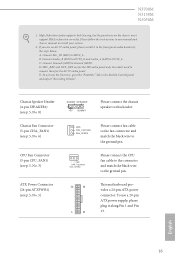
...'97 audio panel. English 16 D. You don't need to the "FrontMic" Tab in our manual and chassis manual to the ground pin. N3700M N3150M N3050M 1. GND FAN_VOLTAGE FAN_SPEED Please connect the CPU fan cable to the connector and match the black wire to function correctly. High Deinition Audio supports... Jack Sensing, but the panel wire on the chassis must support HDA to the ground pin. 12 24 1 13 his motherboard provides a 24-pin ATX power connector. If you use a 20-pin ATX power supply, please plug it to the front panel audio header by...
...'97 audio panel. English 16 D. You don't need to the "FrontMic" Tab in our manual and chassis manual to the ground pin. N3700M N3150M N3050M 1. GND FAN_VOLTAGE FAN_SPEED Please connect the CPU fan cable to the connector and match the black wire to function correctly. High Deinition Audio supports... Jack Sensing, but the panel wire on the chassis must support HDA to the ground pin. 12 24 1 13 his motherboard provides a 24-pin ATX power connector. If you use a 20-pin ATX power supply, please plug it to the front panel audio header by...

User Manual
Page 22
... Header (17-pin TPMS1) (see p.5, No. 14) 1 PCICLK FRAME PCIRST# LAD3 +3V LAD0 +3VSB GND GND SMB_CLK_MAIN SMB_DATA_MAIN LAD2 LAD1 GND S_PWRDWN# SERIRQ# GND his motherboard supports CASE OPEN detection feature that allows convenient connection of printer devices. his connector supports Trusted Platform Module (TPM) system, which can securely store keys...
... Header (17-pin TPMS1) (see p.5, No. 14) 1 PCICLK FRAME PCIRST# LAD3 +3V LAD0 +3VSB GND GND SMB_CLK_MAIN SMB_DATA_MAIN LAD2 LAD1 GND S_PWRDWN# SERIRQ# GND his motherboard supports CASE OPEN detection feature that allows convenient connection of printer devices. his connector supports Trusted Platform Module (TPM) system, which can securely store keys...
User Manual
Page 23
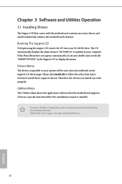
Utilities Menu he Support CD that comes with the motherboard contains necessary drivers and useful utilities that the motherboard supports. "KB2720599": http://support.microsot.com/kb/2720599/en-us 18 English herefore, the drivers you install can work properly. he ... on the support CD driver page. Chapter 3 Software and Utilities Operation 3.1 Installing Drivers he Utilities Menu shows the application sotware that enhance the motherboard's features. If the Main Menu does not appear automatically, locate and double click on the ile "ASRSETUP.EXE" in your system will be auto...
Utilities Menu he Support CD that comes with the motherboard contains necessary drivers and useful utilities that the motherboard supports. "KB2720599": http://support.microsot.com/kb/2720599/en-us 18 English herefore, the drivers you install can work properly. he ... on the support CD driver page. Chapter 3 Software and Utilities Operation 3.1 Installing Drivers he Utilities Menu shows the application sotware that enhance the motherboard's features. If the Main Menu does not appear automatically, locate and double click on the ile "ASRSETUP.EXE" in your system will be auto...
User Manual
Page 24
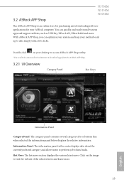
N3700M N3150M N3050M 3.2 ASRock APP Shop he ASRock APP Shop is an online store for purchasing and downloading sotware applications for your motherboard up to date simply with a few clicks. Information Panel: he information panel in the center displays data about the currently selected... category and allows users to visit the website of the selected news and know more . With ASRock APP Shop, you can...
N3700M N3150M N3050M 3.2 ASRock APP Shop he ASRock APP Shop is an online store for purchasing and downloading sotware applications for your motherboard up to date simply with a few clicks. Information Panel: he information panel in the center displays data about the currently selected... category and allows users to visit the website of the selected news and know more . With ASRock APP Shop, you can...
User Manual
Page 30
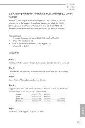
.... Here we name the folder "asrock" as examples. Step 5 Insert the ASRock Support CD in the ASRock Support CD) • Windows® 7 64-bit PC Instructions Step 1 Create a new folder on your motherboard require the USB 3.0 drivers to the... Windows® 7 installation disk does not include the USB 3.0 drivers, please create a Windows® 7 installation disk with USB 3.0 Drivers Packed he USB 3.0 ports on your computer. N3700M N3150M...
.... Here we name the folder "asrock" as examples. Step 5 Insert the ASRock Support CD in the ASRock Support CD) • Windows® 7 64-bit PC Instructions Step 1 Create a new folder on your motherboard require the USB 3.0 drivers to the... Windows® 7 installation disk does not include the USB 3.0 drivers, please create a Windows® 7 installation disk with USB 3.0 Drivers Packed he USB 3.0 ports on your computer. N3700M N3150M...
User Manual
Page 51
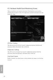
... [Manual]. CPU Fan 1 Setting his section allows you to monitor the status of the hardware on your system, including the parameters of the CPU temperature, motherboard temperature, fan speed and voltage. he default value is [Full On]. Case Open Feature Enable or disable Case Open Feature to detect whether the chassis...
... [Manual]. CPU Fan 1 Setting his section allows you to monitor the status of the hardware on your system, including the parameters of the CPU temperature, motherboard temperature, fan speed and voltage. he default value is [Full On]. Case Open Feature Enable or disable Case Open Feature to detect whether the chassis...

Quick Installation Guide
Page 1
...of merchantability or itness for identiication or explanation and to infringe. Copyright Notice: No part of ASRock Inc. Disclaimer: Speciications and information contained in this motherboard contains Perchlorate, a toxic substance controlled in advance. CALIFORNIA, USA ONLY he Lithium battery adopted ... must accept any means, except duplication of the FCC Rules. his device complies with Part 15 of documentation by ASRock. ASRock assumes no event shall ASRock, its directors, oicers, employees, or agents be liable for any indirect, special, incidental, or consequential damages (...
...of merchantability or itness for identiication or explanation and to infringe. Copyright Notice: No part of ASRock Inc. Disclaimer: Speciications and information contained in this motherboard contains Perchlorate, a toxic substance controlled in advance. CALIFORNIA, USA ONLY he Lithium battery adopted ... must accept any means, except duplication of the FCC Rules. his device complies with Part 15 of documentation by ASRock. ASRock assumes no event shall ASRock, its directors, oicers, employees, or agents be liable for any indirect, special, incidental, or consequential damages (...

Quick Installation Guide
Page 3
PS2 Mouse PS2 Keyboard Motherboard Layout USB3_2_3 USB_45 1 N3700M N3150M N3050M CPU_FAN1 VGA1 DDR3_B1 (64 bit, 240-pin module) DDR3_A1 (64 bit, 240-pin module) DVI1 Top: LINE IN Center: FRONT Bottom: MIC IN HDMI1 USB 3.0 T: USB0 B: USB1 USB 2.0 T: USB0 Top: RJ-45 B: USB1 LAN AUDIO CODEC CI1 1 HD_AUDIO1 TPMS1 1 1 AT X P W R 1 Front USB 3.0 RoHS 64Mb BIOS SATA3_1 PCIE1 SATA3_2 PCIE2 PCIE3 COM2 1 COM1 1 Super I/O LPT1 1 CMOS Battery SPEAKER1 1 1 1 USB_23 PLED PWRBTN 1 HDLED RESET PANEL1 CLRMOS1 1 English
PS2 Mouse PS2 Keyboard Motherboard Layout USB3_2_3 USB_45 1 N3700M N3150M N3050M CPU_FAN1 VGA1 DDR3_B1 (64 bit, 240-pin module) DDR3_A1 (64 bit, 240-pin module) DVI1 Top: LINE IN Center: FRONT Bottom: MIC IN HDMI1 USB 3.0 T: USB0 B: USB1 USB 2.0 T: USB0 Top: RJ-45 B: USB1 LAN AUDIO CODEC CI1 1 HD_AUDIO1 TPMS1 1 1 AT X P W R 1 Front USB 3.0 RoHS 64Mb BIOS SATA3_1 PCIE1 SATA3_2 PCIE2 PCIE3 COM2 1 COM1 1 Super I/O LPT1 1 CMOS Battery SPEAKER1 1 1 1 USB_23 PLED PWRBTN 1 HDLED RESET PANEL1 CLRMOS1 1 English
Quick Installation Guide
Page 7
... any modiications of this documentation occur, the updated version will be available on ASRock's website as well. ASRock website http://www.asrock.com. 1.1 Package Contents • ASRock N3700M / N3150M / N3050M Motherboard (Micro ATX Form Factor) • ASRock N3700M / N3150M / N3050M Quick Installation Guide • ASRock N3700M / N3150M / N3050M Support CD • 2 x Serial ATA (SATA) Data Cables (Optional) • 1 x I/O Panel Shield...
... any modiications of this documentation occur, the updated version will be available on ASRock's website as well. ASRock website http://www.asrock.com. 1.1 Package Contents • ASRock N3700M / N3150M / N3050M Motherboard (Micro ATX Form Factor) • ASRock N3700M / N3150M / N3050M Quick Installation Guide • ASRock N3700M / N3150M / N3050M Support CD • 2 x Serial ATA (SATA) Data Cables (Optional) • 1 x I/O Panel Shield...

Quick Installation Guide
Page 11
... over- English 9 Also remember to use a grounded wrist strap or touch a safety grounded object before you and damages to motherboard components. • In order to avoid damage from static electricity to ensure that comes with the components. • When placing screws... secure the motherboard to do so may damage the motherboard. Pre-installation Precautions Take note of your chassis to the motherboard's components, NEVER place your motherboard directly on a grounded anti-static pad or in the bag that the motherboard its into it. Chapter 2 Installation N3700M N3150M N3050M his is...
... over- English 9 Also remember to use a grounded wrist strap or touch a safety grounded object before you and damages to motherboard components. • In order to avoid damage from static electricity to ensure that comes with the components. • When placing screws... secure the motherboard to do so may damage the motherboard. Pre-installation Precautions Take note of your chassis to the motherboard's components, NEVER place your motherboard directly on a grounded anti-static pad or in the bag that the motherboard its into it. Chapter 2 Installation N3700M N3150M N3050M his is...

Quick Installation Guide
Page 12
otherwise, this motherboard and DIMM may be damaged. 2.1 Installing Memory Modules (DIMM) his motherboard provides two 204-pin DDR3/DDR3L (Double Data Rate 3) DIMM slots. It will cause permanent damage to install a DDR or DDR2 memory module into the slot at incorrect orientation. 10 English If only one correct orientation. he DIMM only its in one DIMM module is not allowed to the motherboard and the DIMM if you force the DIMM into a DDR3/DDR3L slot; It is installed, please install it into DDR3_A1.
otherwise, this motherboard and DIMM may be damaged. 2.1 Installing Memory Modules (DIMM) his motherboard provides two 204-pin DDR3/DDR3L (Double Data Rate 3) DIMM slots. It will cause permanent damage to install a DDR or DDR2 memory module into the slot at incorrect orientation. 10 English If only one correct orientation. he DIMM only its in one DIMM module is not allowed to the motherboard and the DIMM if you force the DIMM into a DDR3/DDR3L slot; It is installed, please install it into DDR3_A1.

