
User Manual
Page 6
... updated, the content of this manual, Chapter 1 and 2 contains the introduction of the BIOS setup. ASRock website http://www.asrock.com. 1.1 Package Contents • ASRock N3700M / N3150M / N3050M Motherboard (Micro ATX Form Factor) • ASRock N3700M / N3150M / N3050M Quick Installation Guide • ASRock N3700M / N3150M / N3050M Support CD • 2 x Serial ATA (SATA) Data Cables (Optional) • 1 x I/O Panel Shield 1 English In this...
... updated, the content of this manual, Chapter 1 and 2 contains the introduction of the BIOS setup. ASRock website http://www.asrock.com. 1.1 Package Contents • ASRock N3700M / N3150M / N3050M Motherboard (Micro ATX Form Factor) • ASRock N3700M / N3150M / N3050M Quick Installation Guide • ASRock N3700M / N3150M / N3050M Support CD • 2 x Serial ATA (SATA) Data Cables (Optional) • 1 x I/O Panel Shield 1 English In this...
User Manual
Page 7
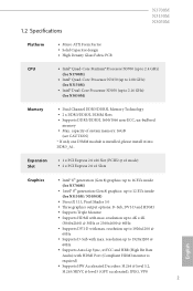
... x1 mode) • 2 x PCI Express 2.0 x1 Slots Graphics • Intel® 8th generation (Gen 8) graphics: up to 16 EUs inside (for N3150M / N3050M) • DirectX 11.1, Pixel Shader 5.0 • hree graphics output options: D-Sub, DVI-D and HDMI • Supports Triple Monitor • Supports HDMI with...; 2 x DDR3/DDR3L DIMM Slots • Supports DDR3/DDR3L 1600/1066 non-ECC, un-bufered memory • Max. 1.2 Speciications N3700M N3150M N3050M Platform • Micro ATX Form Factor • Solid Capacitor design • High Density Glass Fabric PCB CPU • Intel® Quad-...
... x1 mode) • 2 x PCI Express 2.0 x1 Slots Graphics • Intel® 8th generation (Gen 8) graphics: up to 16 EUs inside (for N3150M / N3050M) • DirectX 11.1, Pixel Shader 5.0 • hree graphics output options: D-Sub, DVI-D and HDMI • Supports Triple Monitor • Supports HDMI with...; 2 x DDR3/DDR3L DIMM Slots • Supports DDR3/DDR3L 1600/1066 non-ECC, un-bufered memory • Max. 1.2 Speciications N3700M N3150M N3050M Platform • Micro ATX Form Factor • Solid Capacitor design • High Density Glass Fabric PCB CPU • Intel® Quad-...

User Manual
Page 9
... xHCI drivers packed into the ISO ile is required. N3700M N3150M N3050M • 1 x CPU Fan Connector (3-pin) • 1 x Chassis Fan Connector (3-pin) • 1 x 24 pin ATX Power Connector • 1 x Front Panel Audio Connector • 2 x USB 2.0 Headers (Support 4 USB 2.0 ports) (Supports ESD Protection (ASRock Full Spike Protection)) • 1 x USB 3.0 Header (Supports 2 USB 3.0 ports) (Supports...
... xHCI drivers packed into the ISO ile is required. N3700M N3150M N3050M • 1 x CPU Fan Connector (3-pin) • 1 x Chassis Fan Connector (3-pin) • 1 x 24 pin ATX Power Connector • 1 x Front Panel Audio Connector • 2 x USB 2.0 Headers (Support 4 USB 2.0 ports) (Supports ESD Protection (ASRock Full Spike Protection)) • 1 x USB 3.0 Header (Supports 2 USB 3.0 ports) (Supports...

User Manual
Page 13
N3700M N3150M N3050M ** To conigure 7.1 CH HD Audio, it is required to "7.1 Speaker"in 7.1-channel Coniguration: Port Light Blue (Rear panel) Lime (Rear panel) Pink (Rear panel) Lime (Front panel) Function Rear Speaker Out Front Speaker Out Central /Subwoofer Speaker Out Side Speaker Out 8 English Function of the Audio Ports in the Realtek HD Audio Manager. Please set Speaker Coniguration to use an HD front panel audio module and enable the multichannel audio feature through the audio driver.
N3700M N3150M N3050M ** To conigure 7.1 CH HD Audio, it is required to "7.1 Speaker"in 7.1-channel Coniguration: Port Light Blue (Rear panel) Lime (Rear panel) Pink (Rear panel) Lime (Front panel) Function Rear Speaker Out Front Speaker Out Central /Subwoofer Speaker Out Side Speaker Out 8 English Function of the Audio Ports in the Realtek HD Audio Manager. Please set Speaker Coniguration to use an HD front panel audio module and enable the multichannel audio feature through the audio driver.

User Manual
Page 15
English 10 he DIMM only its in one DIMM module is not allowed to the motherboard and the DIMM if you force the DIMM into a DDR3/DDR3L slot; 2.1 Installing Memory Modules (DIMM) N3700M N3150M N3050M his motherboard provides two 204-pin DDR3/DDR3L (Double Data Rate 3) DIMM slots. otherwise, this motherboard and DIMM may be damaged. It is installed, please install it into DDR3_A1. It will cause permanent damage to install a DDR or DDR2 memory module into the slot at incorrect orientation. If only one correct orientation.
English 10 he DIMM only its in one DIMM module is not allowed to the motherboard and the DIMM if you force the DIMM into a DDR3/DDR3L slot; 2.1 Installing Memory Modules (DIMM) N3700M N3150M N3050M his motherboard provides two 204-pin DDR3/DDR3L (Double Data Rate 3) DIMM slots. otherwise, this motherboard and DIMM may be damaged. It is installed, please install it into DDR3_A1. It will cause permanent damage to install a DDR or DDR2 memory module into the slot at incorrect orientation. If only one correct orientation.
User Manual
Page 17
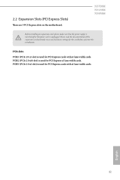
PCIE3 (PCIe 2.0 x1 slot) is used for PCI Express cards with x1 lane width cards. N3700M N3150M N3050M Before installing an expansion card, please make necessary hardware settings for PCI Express cards with x1 lane width cards. PCIE2 (PCIe 2.0 x16 slot) is used ...
PCIE3 (PCIe 2.0 x1 slot) is used for PCI Express cards with x1 lane width cards. N3700M N3150M N3050M Before installing an expansion card, please make necessary hardware settings for PCI Express cards with x1 lane width cards. PCIE2 (PCIe 2.0 x16 slot) is used ...

User Manual
Page 19
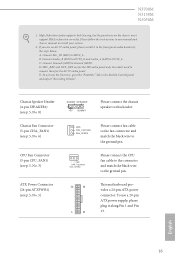
... chassis front panel module to this header according to perform a normal restart. When connecting your system using the power switch. 2.4 Onboard Headers and Connectors N3700M N3150M N3050M Onboard headers and connectors are matched correctly. HDLED (Hard Drive Activity LED): Connect to the power status indicator on when the hard drive is operating...
... chassis front panel module to this header according to perform a normal restart. When connecting your system using the power switch. 2.4 Onboard Headers and Connectors N3700M N3150M N3050M Onboard headers and connectors are matched correctly. HDLED (Hard Drive Activity LED): Connect to the power status indicator on when the hard drive is operating...
User Manual
Page 21
... the black wire to OUT2_L. GND FAN_VOLTAGE FAN_SPEED Please connect the CPU fan cable to the connector and match the black wire to MIC2_L. N3700M N3150M N3050M 1. E. Please follow the instructions in the Realtek Control panel and adjust "Recording Volume". Connect Mic_IN (MIC) to the ground pin. 12 24 1 13 his motherboard...
... the black wire to OUT2_L. GND FAN_VOLTAGE FAN_SPEED Please connect the CPU fan cable to the connector and match the black wire to MIC2_L. N3700M N3150M N3050M 1. E. Please follow the instructions in the Realtek Control panel and adjust "Recording Volume". Connect Mic_IN (MIC) to the ground pin. 12 24 1 13 his motherboard...
User Manual
Page 24
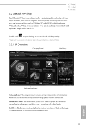
...about the currently selected category and allows users to visit the website of the selected news and know more . Click on your desktop to access ASRock APP Shop utility. *You need to be connected to the Internet to date simply with a few clicks. You can optimize your system and ...utilities, such as USB Key, XFast LAN, XFast RAM and more . 19 English Double-click on the image to perform job-related tasks. N3700M N3150M N3050M 3.2 ASRock APP Shop he ASRock APP Shop is an online store for purchasing and downloading sotware applications for your motherboard up to download apps from the...
...about the currently selected category and allows users to visit the website of the selected news and know more . Click on your desktop to access ASRock APP Shop utility. *You need to be connected to the Internet to date simply with a few clicks. You can optimize your system and ...utilities, such as USB Key, XFast LAN, XFast RAM and more . 19 English Double-click on the image to perform job-related tasks. N3700M N3150M N3050M 3.2 ASRock APP Shop he ASRock APP Shop is an online store for purchasing and downloading sotware applications for your motherboard up to download apps from the...

User Manual
Page 26
Step 4 When installation completes, you want to start downloading. Step 3 If you can icon . *he trash icon may not appear for certain apps. 21 English To uninstall it, simply click on the trash can ind the green "Installed" icon appears on the red icon N3700M N3150M N3050M to install the app, click on the upper right corner.
Step 4 When installation completes, you want to start downloading. Step 3 If you can icon . *he trash icon may not appear for certain apps. 21 English To uninstall it, simply click on the trash can ind the green "Installed" icon appears on the red icon N3700M N3150M N3050M to install the app, click on the upper right corner.

User Manual
Page 28
Step 3 Click Update to see more items you will see a list of recommended or critical updates for the BIOS or drivers. Please update them all soon. Step 1 Please check the item information before update. 3.2.3 BIOS & Drivers N3700M N3150M N3050M Installing BIOS or Drivers When the "BIOS & Drivers" tab is selected, you want to update. Click on Step 2 to start the update process. 23 English Click to select one or more details.
Step 3 Click Update to see more items you will see a list of recommended or critical updates for the BIOS or drivers. Please update them all soon. Step 1 Please check the item information before update. 3.2.3 BIOS & Drivers N3700M N3150M N3050M Installing BIOS or Drivers When the "BIOS & Drivers" tab is selected, you want to update. Click on Step 2 to start the update process. 23 English Click to select one or more details.
User Manual
Page 30
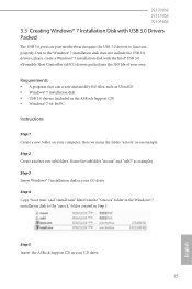
...drivers, please create a Windows® 7 installation disk with USB 3.0 Drivers Packed he USB 3.0 ports on your computer. Here we name the folder "asrock" as examples. Name the subfolder "mount" and "usb3" as an example. Step 4 Copy "boot.wim" and "install.wim" iles from the "...Sources" folder in your CD drive. 25 English Step 5 Insert the ASRock Support CD in Step 1. Due to the "asrock" folder created in your CD drive. N3700M N3150M N3050M 3.3 Creating Windows® 7 Installation Disk with the Intel® USB 3.0 eXtensible Host Controller (xHCI...
...drivers, please create a Windows® 7 installation disk with USB 3.0 Drivers Packed he USB 3.0 ports on your computer. Here we name the folder "asrock" as examples. Name the subfolder "mount" and "usb3" as an example. Step 4 Copy "boot.wim" and "install.wim" iles from the "...Sources" folder in your CD drive. 25 English Step 5 Insert the ASRock Support CD in Step 1. Due to the "asrock" folder created in your CD drive. N3700M N3150M N3050M 3.3 Creating Windows® 7 Installation Disk with the Intel® USB 3.0 eXtensible Host Controller (xHCI...

User Manual
Page 32
... "boot.wim" in order to install Windows® 7 by lash3.0, please input the following commands in order and wait until the each process completes. N3700M N3150M N3050M Step 9 To add USB 3.0 drivers into the "install.wim" image ile, please input the following commands in order and wait until the each process completes...
... "boot.wim" in order to install Windows® 7 by lash3.0, please input the following commands in order and wait until the each process completes. N3700M N3150M N3050M Step 9 To add USB 3.0 drivers into the "install.wim" image ile, please input the following commands in order and wait until the each process completes...
User Manual
Page 34
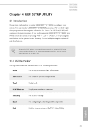
... Boot For coniguring boot settings and boot priority Exit Exit the current screen or the UEFI Setup Utility English 29 Chapter 4 UEFI SETUP UTILITY N3700M N3150M N3050M 4.1 Introduction his section explains how to use the UEFI SETUP UTILITY to enter the UEFI SETUP UTILITY ater POST, restart the system by pressing + + , or...
... Boot For coniguring boot settings and boot priority Exit Exit the current screen or the UEFI Setup Utility English 29 Chapter 4 UEFI SETUP UTILITY N3700M N3150M N3050M 4.1 Introduction his section explains how to use the UEFI SETUP UTILITY to enter the UEFI SETUP UTILITY ater POST, restart the system by pressing + + , or...

User Manual
Page 36
N3700M N3150M N3050M N3700M: N3150M: 31 English 4.2 Main Screen When you enter the UEFI SETUP UTILITY, the Main screen will appear and display the system overview.
N3700M N3150M N3050M N3700M: N3150M: 31 English 4.2 Main Screen When you enter the UEFI SETUP UTILITY, the Main screen will appear and display the system overview.

User Manual
Page 38
N3700M N3150M N3050M 4.3 Advanced Screen In this section may set the conigurations for the following items: CPU Coniguration, Chipset Coniguration, Storage Coniguration, IntelRMT Coniguration, Super IO Coniguration, ACPI Coniguration, USB Coniguration and Trusted Computing. Setting wrong values in this section, you may cause the system to malfunction. 33 English
N3700M N3150M N3050M 4.3 Advanced Screen In this section may set the conigurations for the following items: CPU Coniguration, Chipset Coniguration, Storage Coniguration, IntelRMT Coniguration, Super IO Coniguration, ACPI Coniguration, USB Coniguration and Trusted Computing. Setting wrong values in this section, you may cause the system to malfunction. 33 English

User Manual
Page 40
Front Panel Enable/disable front panel HD audio. 4.3.2 Chipset Coniguration N3700M N3150M N3050M DRAM Voltage Use this to the integrated graphics processor when the system boots up. Onboard HD Audio Enable/disable onboard HD audio. Onboard LAN Enable ...
Front Panel Enable/disable front panel HD audio. 4.3.2 Chipset Coniguration N3700M N3150M N3050M DRAM Voltage Use this to the integrated graphics processor when the system boots up. Onboard HD Audio Enable/disable onboard HD audio. Onboard LAN Enable ...

User Manual
Page 42
... new features that will improve SATA disk performance. Aggressive Link Power Management Aggressive Link Power Management allows SATA devices to save power. 4.3.3 Storage Coniguration N3700M N3150M N3050M SATA Controller(s) Enable/disable the SATA controllers. AHCI (Advanced Host Controller Interface) supports NCQ and other new features that improve performance. It is a monitoring system...
... new features that will improve SATA disk performance. Aggressive Link Power Management Aggressive Link Power Management allows SATA devices to save power. 4.3.3 Storage Coniguration N3700M N3150M N3050M SATA Controller(s) Enable/disable the SATA controllers. AHCI (Advanced Host Controller Interface) supports NCQ and other new features that improve performance. It is a monitoring system...

User Manual
Page 44
Serial Port 2 Enable or disable the Serial port 2. Serial Port Address Select the address of the Parallel port. Parallel Port Enable or disable the Parallel port. Device Mode Select the device mode according to your connected device. 39 English Change Settings Select the address of the Serial port. Serial Port Address Select the address of the Serial port. 4.3.5 Super IO Coniguration N3700M N3150M N3050M Serial Port 1 Enable or disable the Serial port 1.
Serial Port 2 Enable or disable the Serial port 2. Serial Port Address Select the address of the Parallel port. Parallel Port Enable or disable the Parallel port. Device Mode Select the device mode according to your connected device. 39 English Change Settings Select the address of the Serial port. Serial Port Address Select the address of the Serial port. 4.3.5 Super IO Coniguration N3700M N3150M N3050M Serial Port 1 Enable or disable the Serial port 1.

User Manual
Page 46
N3700M N3150M N3050M English 41 USB Mouse Power On Allow the system to be waked up by an USB mouse. USB Keyboard/Remote Power On Allow the system to be waked up by an USB keyboard or remote controller.
N3700M N3150M N3050M English 41 USB Mouse Power On Allow the system to be waked up by an USB mouse. USB Keyboard/Remote Power On Allow the system to be waked up by an USB keyboard or remote controller.