User Manual
Page 3
...Menu 23 3. Contents 1 Introduction 4 1.1 Package Contents 4 1.2 Specifications 4 1.3 Motherboard Layout 6 1.4 ASRock I/OTM 7 2 Installation 8 2.1 Screw Holes 8 2.2 Pre-installation Precautions 8 2.3 CPU Installation 8 2.4 Installation of Heatsink and CPU fan 9 2.5 Installation of Memory Modules (DIMM 9 2.6 Expansion Slots 10 2.7 Jumpers Setup 10 2.8 Connectors 11 3 BIOS Setup 14 3.1... 4.2 Support CD Information 18 4.2.1 Running Support CD 18 4.2.2 Drivers Menu 18 4.2.3 Utilities Menu 18 4.2.4 ASRock "PC-DIY Live Demo" Program 18 4.2.5 Contact Information 18 Appendix 19 1.
...Menu 23 3. Contents 1 Introduction 4 1.1 Package Contents 4 1.2 Specifications 4 1.3 Motherboard Layout 6 1.4 ASRock I/OTM 7 2 Installation 8 2.1 Screw Holes 8 2.2 Pre-installation Precautions 8 2.3 CPU Installation 8 2.4 Installation of Heatsink and CPU fan 9 2.5 Installation of Memory Modules (DIMM 9 2.6 Expansion Slots 10 2.7 Jumpers Setup 10 2.8 Connectors 11 3 BIOS Setup 14 3.1... 4.2 Support CD Information 18 4.2.1 Running Support CD 18 4.2.2 Drivers Menu 18 4.2.3 Utilities Menu 18 4.2.4 ASRock "PC-DIY Live Demo" Program 18 4.2.5 Contact Information 18 Appendix 19 1.

User Manual
Page 4
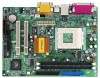
... floppy disk drive 4 ASRock website http://www.asrock.com 1.1 Package Contents ASRock M810LMR motherboard (Micro ATX form factor: 9.6" x 7.0", 24.4 x 17.8 cm) ASRock M810LMR Quick Installation Guide ASRock AMD-VIA Series Support CD 1 cable for IDE devices (1 x ATA 66/100) 1 cable for floppy drive (1 x ribbon cable) 1 ASRock I/O shield 1 COM port bracket 1.2 Specifications Platform: CPU: Chipsets: Clock Generator: Memory: IDE: Floppy...
... floppy disk drive 4 ASRock website http://www.asrock.com 1.1 Package Contents ASRock M810LMR motherboard (Micro ATX form factor: 9.6" x 7.0", 24.4 x 17.8 cm) ASRock M810LMR Quick Installation Guide ASRock AMD-VIA Series Support CD 1 cable for IDE devices (1 x ATA 66/100) 1 cable for floppy drive (1 x ribbon cable) 1 ASRock I/O shield 1 COM port bracket 1.2 Specifications Platform: CPU: Chipsets: Clock Generator: Memory: IDE: Floppy...

User Manual
Page 5
...: PCI slots: AMR slot: ASRock I/OTM: BIOS: OS: 2 channels AC'97 Audio Speed...10/100 Ethernet), supports Wake-On-LAN CPU temperature sensing (ASRock U-COP); Voltage monitoring: +12V, +5V, +3V,...Chassis fan tachometer 2 slots with PCI Specification 2.1 1 slot, supports ASRock MR card (optional) PS/2: 1 keyboard port / 1 mouse port... CPU bus frequencies may cause the instability of M810LMR is set to perform over clocking. CPU fan...ASRock U-COP) (see CAUTION 2) Microsoft® Windows® 98 SE / ME / 2000 / XP compliant CAUTION! 1. Supports "Plug and Play"; Although M810LMR...
...: PCI slots: AMR slot: ASRock I/OTM: BIOS: OS: 2 channels AC'97 Audio Speed...10/100 Ethernet), supports Wake-On-LAN CPU temperature sensing (ASRock U-COP); Voltage monitoring: +12V, +5V, +3V,...Chassis fan tachometer 2 slots with PCI Specification 2.1 1 slot, supports ASRock MR card (optional) PS/2: 1 keyboard port / 1 mouse port... CPU bus frequencies may cause the instability of M810LMR is set to perform over clocking. CPU fan...ASRock U-COP) (see CAUTION 2) Microsoft® Windows® 98 SE / ME / 2000 / XP compliant CAUTION! 1. Supports "Plug and Play"; Although M810LMR...

User Manual
Page 9
... pins. For proper installation, please kindly refer to a 90o angle. Step 2. Please make sure to indicate that its marked corner matches the base of Memory Modules (DIMM) M810LMR motherboard provides two 168-pin SDRAM DIMM slots. Step 3. Unlock a DIMM slot by lifting the lever up to the instruction manuals of vendors of...
... pins. For proper installation, please kindly refer to a 90o angle. Step 2. Please make sure to indicate that its marked corner matches the base of Memory Modules (DIMM) M810LMR motherboard provides two 168-pin SDRAM DIMM slots. Step 3. Unlock a DIMM slot by lifting the lever up to the instruction manuals of vendors of...

User Manual
Page 14
... BOOT Configures the default system device that is used to enter the BIOS Setup Utility, otherwise, POST continues with their corresponding functions. 14 The Flash Memory on your system using the BIOS Setup Utility. When you see on the motherboard stores the BIOS Setup Utility. Chapter 3 BIOS Setup 3.1 BIOS Setup Utility...
... BOOT Configures the default system device that is used to enter the BIOS Setup Utility, otherwise, POST continues with their corresponding functions. 14 The Flash Memory on your system using the BIOS Setup Utility. When you see on the motherboard stores the BIOS Setup Utility. Chapter 3 BIOS Setup 3.1 BIOS Setup Utility...

User Manual
Page 15
... System Time Floppy Drives IDE Devices BIOS Version Processor Type Processor Speed L1 Cache Size L2 Cache Size Total Memory SDR1 SDR2 AMIBIOS SETUP UTILITY - Dec Day: 01 - 31 Year: 1980 - 2099 M810LMR BIOS P1.00 AMD Athlon(tm) XP 2200+ 1800 MHz 128 KB 256 KB 224 MB + 32 MB Share... Memory 256 MB / 133 MHz None F1:Help Esc:Exit :Select Item :Select Menu +/-:Change Values Enter:Select Sub-Menu F9...
... System Time Floppy Drives IDE Devices BIOS Version Processor Type Processor Speed L1 Cache Size L2 Cache Size Total Memory SDR1 SDR2 AMIBIOS SETUP UTILITY - Dec Day: 01 - 31 Year: 1980 - 2099 M810LMR BIOS P1.00 AMD Athlon(tm) XP 2200+ 1800 MHz 128 KB 256 KB 224 MB + 32 MB Share... Memory 256 MB / 133 MHz None F1:Help Esc:Exit :Select Item :Select Menu +/-:Change Values Enter:Select Sub-Menu F9...

User Manual
Page 19
... Power Boot Exit Spread Spectrum CPU Host Frequency Actual Frequency SDRAM Frequency Disabled By Jumper 133MHz Auto [ Setup Help ] to [Auto], the motherboard detects the memory module(s) inserted and automatically assigns appropriate frequency. Chipset Configuration Resource Configuration Peripheral Configuration System Hardware Monitor F1:Help Esc:Exit :Select Item :Select Menu +/-:Change...
... Power Boot Exit Spread Spectrum CPU Host Frequency Actual Frequency SDRAM Frequency Disabled By Jumper 133MHz Auto [ Setup Help ] to [Auto], the motherboard detects the memory module(s) inserted and automatically assigns appropriate frequency. Chipset Configuration Resource Configuration Peripheral Configuration System Hardware Monitor F1:Help Esc:Exit :Select Item :Select Menu +/-:Change...

User Manual
Page 20
...not PCI 2.1 compliant. If the graphics card is inserted. USB Controller: Use this to enable or disable the support to adjust the means of memory accessing. 20 When [Auto] is selected, the system will auto-detect if any graphics card is detected, the onboard VGA will be automatically set... Defaults F10:Save & Exit PCI Delay Transaction: Enable PCI Delay Transaction feature will free the PCI Bus when the CPU is detected, the share memory for the onboard VGA. etc. USB Device Legacy Support: Use this to set as mouse, keyboard,... SDRAM CAS Latency: This is accessing 8-bit...
...not PCI 2.1 compliant. If the graphics card is inserted. USB Controller: Use this to enable or disable the support to adjust the means of memory accessing. 20 When [Auto] is selected, the system will auto-detect if any graphics card is detected, the onboard VGA will be automatically set... Defaults F10:Save & Exit PCI Delay Transaction: Enable PCI Delay Transaction feature will free the PCI Bus when the CPU is detected, the share memory for the onboard VGA. etc. USB Device Legacy Support: Use this to set as mouse, keyboard,... SDRAM CAS Latency: This is accessing 8-bit...

User Manual
Page 25
... enter the sub-menu, the message "Load setup original values" will appear. Load Default Settings: After you press , it will boot-up routine by skipping memory retestings. All changes are discarded. 25 VERSION 3.31a Security Power Boot Exit Exit Saving Changes Exit Discarding Changes Load Default Settings Discard Changes [ Enter ] [ Enter...
... enter the sub-menu, the message "Load setup original values" will appear. Load Default Settings: After you press , it will boot-up routine by skipping memory retestings. All changes are discarded. 25 VERSION 3.31a Security Power Boot Exit Exit Saving Changes Exit Discarding Changes Load Default Settings Discard Changes [ Enter ] [ Enter...

