
User Manual
Page 4
... 3.4.1 CPU Configuration 59 3.4.2 Memory Configuration 61 3.4.3 Chipset Configuration 65 3.4.4 ACPI Configuration 67 3.4.5 Storage Configuration 69 3.4.6 PCIPnP Configuration 71 3.4.7 Floppy Configuration 72 3.4.8 Super IO Configuration 72 3.4.9 USB Configuration 73 3.5 Hardware Health Event Monitoring Screen 74 3.6 Boot Screen 75 3.6.1 Boot Settings Configuration 75 3.7 Security Screen 76 3.8 Exit Screen 77 4 . Software Support 78 4.1 Install...
... 3.4.1 CPU Configuration 59 3.4.2 Memory Configuration 61 3.4.3 Chipset Configuration 65 3.4.4 ACPI Configuration 67 3.4.5 Storage Configuration 69 3.4.6 PCIPnP Configuration 71 3.4.7 Floppy Configuration 72 3.4.8 Super IO Configuration 72 3.4.9 USB Configuration 73 3.5 Hardware Health Event Monitoring Screen 74 3.6 Boot Screen 75 3.6.1 Boot Settings Configuration 75 3.7 Security Screen 76 3.8 Exit Screen 77 4 . Software Support 78 4.1 Install...

User Manual
Page 5
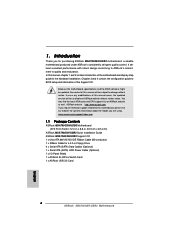
... cards and CPU support lists on ASRock website without notice. www.asrock.com/support/index.asp 1.1 Package Contents ASRock M3A790GXH/USB3 Motherboard (ATX Form Factor: 12.0-in x 8.8-in Floppy Drive 4 x Serial ATA (SATA) Data Cables (Optional) 1 x Serial ATA (SATA) HDD Power Cable (Optional) 1 x I/O Panel Shield 1 x ASRock SLI/XFire Switch Card 1 x ASRock USB 3.0 Card 5 In case any modifications of...
... cards and CPU support lists on ASRock website without notice. www.asrock.com/support/index.asp 1.1 Package Contents ASRock M3A790GXH/USB3 Motherboard (ATX Form Factor: 12.0-in x 8.8-in Floppy Drive 4 x Serial ATA (SATA) Data Cables (Optional) 1 x Serial ATA (SATA) HDD Power Cable (Optional) 1 x I/O Panel Shield 1 x ASRock SLI/XFire Switch Card 1 x ASRock USB 3.0 Card 5 In case any modifications of...

User Manual
Page 7
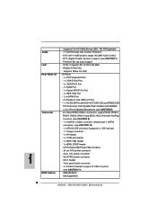
...1 x VGA/D-Sub Port - 1 x VGA/DVI-D Port - 1 x HDMI Port - 1 x Optical SPDIF Out Port - 1 x IEEE 1394 Port - 1 x eSATAII Port - 6 x Ready-to-Use USB 2.0 Ports - 1 x RJ-45 LAN Port with Content Protection - DTS (Digital Theater Systems) support (see CAUTION 10) - 1 x ATA133 IDE connector (supports 2 x IDE devices) - 1 x Floppy connector...SPEED LED) - HD Audio Jack: Side Speaker/Rear Speaker/Central/Bass/ Line in header - Front panel audio connector - 3 x USB 2.0 headers (support 6 USB 2.0 ports) (see CAUTION 11) - 8Mb AMI BIOS - AMI Legal BIOS 7 PCIE x1 Gigabit LAN 10/100/1000 Mb/s...
...1 x VGA/D-Sub Port - 1 x VGA/DVI-D Port - 1 x HDMI Port - 1 x Optical SPDIF Out Port - 1 x IEEE 1394 Port - 1 x eSATAII Port - 6 x Ready-to-Use USB 2.0 Ports - 1 x RJ-45 LAN Port with Content Protection - DTS (Digital Theater Systems) support (see CAUTION 10) - 1 x ATA133 IDE connector (supports 2 x IDE devices) - 1 x Floppy connector...SPEED LED) - HD Audio Jack: Side Speaker/Rear Speaker/Central/Bass/ Line in header - Front panel audio connector - 3 x USB 2.0 headers (support 6 USB 2.0 ports) (see CAUTION 11) - 8Mb AMI BIOS - AMI Legal BIOS 7 PCIE x1 Gigabit LAN 10/100/1000 Mb/s...

User Manual
Page 9
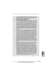
...information. 7. Whether 1600MHz memory speed is defined by hardware monitor function and overclock your hardware devices to SATAII mode. ASRock website http://www.asrock.com 4. DTS (Digital Theater Systems) is a revolutionary technology that delivers unparalleled power savings. Featuring an advanced proprietary ...64-bit CPU, there is able to the operating system limitation, the actual memory size may be less than 4GB for the reservation for USB 2.0 works fine under Windows® 7 / VistaTM / XP. Please check AMD website for proper connection. 9. For microphone input, this...
...information. 7. Whether 1600MHz memory speed is defined by hardware monitor function and overclock your hardware devices to SATAII mode. ASRock website http://www.asrock.com 4. DTS (Digital Theater Systems) is a revolutionary technology that delivers unparalleled power savings. Featuring an advanced proprietary ...64-bit CPU, there is able to the operating system limitation, the actual memory size may be less than 4GB for the reservation for USB 2.0 works fine under Windows® 7 / VistaTM / XP. Please check AMD website for proper connection. 9. For microphone input, this...
User Manual
Page 10
...for the completed system. For EuP ready power supply selection, we recommend you can load the OC profile to their own system to your USB flash drive, floppy disk or hard drive, then you checking with your BIOS only in off mode condition. Just launch this tool and save...must use Intelligent Energy Saver function, please enable Cool 'n' Quiet option in the BIOS setup in Flash ROM. ASRock Instant Flash is not recommended to access ASRock Instant Flash. ASRock website: http://www.asrock.com 14. With OC DNA, you can save your OC settings as yours! Before you install the PC ...
...for the completed system. For EuP ready power supply selection, we recommend you can load the OC profile to their own system to your USB flash drive, floppy disk or hard drive, then you checking with your BIOS only in off mode condition. Just launch this tool and save...must use Intelligent Energy Saver function, please enable Cool 'n' Quiet option in the BIOS setup in Flash ROM. ASRock Instant Flash is not recommended to access ASRock Instant Flash. ASRock website: http://www.asrock.com 14. With OC DNA, you can save your OC settings as yours! Before you install the PC ...

User Manual
Page 12
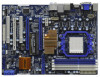
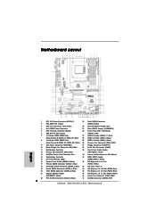
...USB2 USB3 Phenom II USB 2.0 T: USB0 B: USB1 Top: RJ-45 CPU_FAN1 Sideport memory 128MB SLI/XFIRE_PWR1 Top: SIDE SPK Center: REAR SPK FRONT Bottom: CTR BASS MIC IN AMD Top: LINE IN Center: Bottom: 790GX NB_FAN1 41 PWR_FAN1 Chipset PCIE1 LAN PHY 40 M3A790GXH/USB3 39...) 5 CPU Heatsink Retention Module 26 Front Panel IEEE 1394 Header 6 AM3 941-Pin CPU Socket (FRONT_1394) 7 2 x 240-pin DDR3 DIMM Slots 27 USB 2.0 Header (USB10_11, Blue) (Dual Channel A: DDR3_A1, DDR3_B1; White) (SPEAKER 1, White) 41 Power Fan Connector (PWR_FAN1) 22 Fifth SATAII Connector (SATAII_5...
...USB2 USB3 Phenom II USB 2.0 T: USB0 B: USB1 Top: RJ-45 CPU_FAN1 Sideport memory 128MB SLI/XFIRE_PWR1 Top: SIDE SPK Center: REAR SPK FRONT Bottom: CTR BASS MIC IN AMD Top: LINE IN Center: Bottom: 790GX NB_FAN1 41 PWR_FAN1 Chipset PCIE1 LAN PHY 40 M3A790GXH/USB3 39...) 5 CPU Heatsink Retention Module 26 Front Panel IEEE 1394 Header 6 AM3 941-Pin CPU Socket (FRONT_1394) 7 2 x 240-pin DDR3 DIMM Slots 27 USB 2.0 Header (USB10_11, Blue) (Dual Channel A: DDR3_A1, DDR3_B1; White) (SPEAKER 1, White) 41 Power Fan Connector (PWR_FAN1) 22 Fifth SATAII Connector (SATAII_5...

User Manual
Page 13
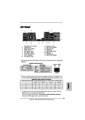
... for the LAN port LED indications. 1.6 I/O Panel 1 2 34 58 69 7 10 17 16 15 14 13 12 11 1 PS/2 Keyboard Port (Purple) 2 VGA/D-Sub Port 3 USB 2.0 Ports (USB23) * 4 LAN RJ-45 Port 5 Side Speaker (Gray) 6 Rear Speaker (Black) 7 Central / Bass (Orange) 8 Line In (Light Blue) ** 9 Front Speaker ...(Lime) 10 11 12 13 14 *** 15 16 17 Microphone (Pink) USB 2.0 Ports (USB01) IEEE 1394 Port eSATAII Port Optical SPDIF Out Port HDMI Port VGA/DVI-D Port USB 2.0 Ports (USB45) * There are two LED next to stereo 2 channels only. 13
... for the LAN port LED indications. 1.6 I/O Panel 1 2 34 58 69 7 10 17 16 15 14 13 12 11 1 PS/2 Keyboard Port (Purple) 2 VGA/D-Sub Port 3 USB 2.0 Ports (USB23) * 4 LAN RJ-45 Port 5 Side Speaker (Gray) 6 Rear Speaker (Black) 7 Central / Bass (Orange) 8 Line In (Light Blue) ** 9 Front Speaker ...(Lime) 10 11 12 13 14 *** 15 16 17 Microphone (Pink) USB 2.0 Ports (USB01) IEEE 1394 Port eSATAII Port Optical SPDIF Out Port HDMI Port VGA/DVI-D Port USB 2.0 Ports (USB45) * There are two LED next to stereo 2 channels only. 13

User Manual
Page 32
... pin3 on CLRCMOS1 for 5 seconds. The data in CMOS. The illustration shows a 3-pin jumper whose pin1 and pin2 are setup. After waiting for PS/2 or USB wake up the system first, and then shut it requires 2 Amp and higher standby current provided by power supply. If you need to clear the...
... pin3 on CLRCMOS1 for 5 seconds. The data in CMOS. The illustration shows a 3-pin jumper whose pin1 and pin2 are setup. After waiting for PS/2 or USB wake up the system first, and then shut it requires 2 Amp and higher standby current provided by power supply. If you need to clear the...

User Manual
Page 34
...data cable to receive stereo audio input from sound sources such as a CD-ROM, DVD-ROM, TV tuner card, or MPEG card. Each USB 2.0 header can support two USB 2.0 ports. Serial ATA (SATA) Data Cable (Optional) Serial ATA (SATA) Power Cable (Optional) connect to the SATA HDD power connector ...connect to the power supply USB 2.0 Headers (9-pin USB10_11) (see p.12 No. 27) (9-pin USB8_9) (see p.12 No. 29) (9-pin USB6_7) (see p.12 No. 28) USB_PWR P-11 P+11 GND DUMMY...
...data cable to receive stereo audio input from sound sources such as a CD-ROM, DVD-ROM, TV tuner card, or MPEG card. Each USB 2.0 header can support two USB 2.0 ports. Serial ATA (SATA) Data Cable (Optional) Serial ATA (SATA) Power Cable (Optional) connect to the SATA HDD power connector ...connect to the power supply USB 2.0 Headers (9-pin USB10_11) (see p.12 No. 27) (9-pin USB8_9) (see p.12 No. 29) (9-pin USB6_7) (see p.12 No. 28) USB_PWR P-11 P+11 GND DUMMY...

User Manual
Page 41
...basis of your computer, offering the high speed data transfer rate up to exchange your chassis to 3.0Gb/s, and the convenient mobility like USB. This motherboard supports eSATAII interface, the external SATAII specification. However, eSATAII provides the data transfer rate up to the eSATAII ports instead .... For example, with Hot Plug capability that eSATAII HDD should have. 5. Please refer to page 47 to 50 for detailed information of USB 2.0 is up to 480Mb/s, and for external interface. otherwise, it may simply plug your eSATAII devices to the eSATAII ports while the ...
...basis of your computer, offering the high speed data transfer rate up to exchange your chassis to 3.0Gb/s, and the convenient mobility like USB. This motherboard supports eSATAII interface, the external SATAII specification. However, eSATAII provides the data transfer rate up to the eSATAII ports instead .... For example, with Hot Plug capability that eSATAII HDD should have. 5. Please refer to page 47 to 50 for detailed information of USB 2.0 is up to 480Mb/s, and for external interface. otherwise, it may simply plug your eSATAII devices to the eSATAII ports while the ...
User Manual
Page 57
...reboot your BIOS only in Flash ROM. This convenient BIOS update tool allows you execute ASRock Instant Flash utility, the utility will show the BIOS files and their respective information. If you to your USB flash drive, floppy disk or hard drive, then you can update your system after ...BIOS update process completes. 57 Please be noted that the USB flash drive or hard drive must use FAT32/16/ 12 file system. ASRock Instant Flash ASRock Instant Flash is a BIOS flash utility embedded in a few clicks without entering operating systems first like...
...reboot your BIOS only in Flash ROM. This convenient BIOS update tool allows you execute ASRock Instant Flash utility, the utility will show the BIOS files and their respective information. If you to your USB flash drive, floppy disk or hard drive, then you can update your system after ...BIOS update process completes. 57 Please be noted that the USB flash drive or hard drive must use FAT32/16/ 12 file system. ASRock Instant Flash ASRock Instant Flash is a BIOS flash utility embedded in a few clicks without entering operating systems first like...

User Manual
Page 58
... Configuration, Memory Configuration, Chipset Configuration, ACPI Configuration, Storage Configuration, PCIPnP Configuration, Floppy Configuration, SuperIO Configuration, and USB Configuration. CPU Configuration Memory Configuration Chipset Configuration ACPI Configuration Storage Configuration PCIPnP Configuration Floppy Configuration SuperIO Configuration USB Configuration Select Screen Select Item Enter Go to adjust PCIE frequency. 58 If Manual, multiplier and voltage...
... Configuration, Memory Configuration, Chipset Configuration, ACPI Configuration, Storage Configuration, PCIPnP Configuration, Floppy Configuration, SuperIO Configuration, and USB Configuration. CPU Configuration Memory Configuration Chipset Configuration ACPI Configuration Storage Configuration PCIPnP Configuration Floppy Configuration SuperIO Configuration USB Configuration Select Screen Select Item Enter Go to adjust PCIE frequency. 58 If Manual, multiplier and voltage...

User Manual
Page 73
...Setup Only]. There are allowed to select legacy support for the details of USB controller. Legacy USB Support Use this item to below descriptions for USB devices. USB devices are connected. [Disabled] - USB Controller Use this option to use only under legacy OS and BIOS setup...under BIOS setup and Windows / Linux OS. 73 3.4.9 USB Configuration BIOS SETUP UTILITY Advanced USB Configuration USB Controller USB 2.0 Support Legacy USB Support [Enabled] [Enabled] [Enabled] To enable or disable the onboard USB controllers. +F1 F9 F10 ESC Select Screen Select Item ...
...Setup Only]. There are allowed to select legacy support for the details of USB controller. Legacy USB Support Use this item to below descriptions for USB devices. USB devices are connected. [Disabled] - USB Controller Use this option to use only under legacy OS and BIOS setup...under BIOS setup and Windows / Linux OS. 73 3.4.9 USB Configuration BIOS SETUP UTILITY Advanced USB Configuration USB Controller USB 2.0 Support Legacy USB Support [Enabled] [Enabled] [Enabled] To enable or disable the onboard USB controllers. +F1 F9 F10 ESC Select Screen Select Item ...

User Manual
Page 75
3.6 Boot Screen In this option to adjust AddOn ROM Display. ROM C] [USB] [USB] Select Screen Select Item Enter Go to enable or disable OEM Logo. AddOn ROM Display Use this section, it will display the available devices on ...
3.6 Boot Screen In this option to adjust AddOn ROM Display. ROM C] [USB] [USB] Select Screen Select Item Enter Go to enable or disable OEM Logo. AddOn ROM Display Use this section, it will display the available devices on ...
Quick Installation Guide
Page 2
...Pin CPU Socket (FRONT_1394) 7 2 x 240-pin DDR3 DIMM Slots 27 USB 2.0 Header (USB10_11, Blue) (Dual Channel A: DDR3_A1, DDR3_B1; Blue) 28 USB 2.0 Header (USB6_7, Blue) 8 2 x 240-pin DDR3 DIMM Slots 29 USB 2.0 Header (USB8_9, Blue) (Dual Channel B: DDR3_A2, DDR3_B2; Blue)... 21 Chassis Speaker Header 40 PCI Express 2.0 x1 Slot (PCIE1; White) (SPEAKER 1, White) 41 Power Fan Connector (PWR_FAN1) 22 Fifth SATAII Connector (SATAII_5, Blue) 42 eSATAII Connector (eSATAII_TOP) 2 ASRock M3A790GXH/USB3 Motherboard ...
...Pin CPU Socket (FRONT_1394) 7 2 x 240-pin DDR3 DIMM Slots 27 USB 2.0 Header (USB10_11, Blue) (Dual Channel A: DDR3_A1, DDR3_B1; Blue) 28 USB 2.0 Header (USB6_7, Blue) 8 2 x 240-pin DDR3 DIMM Slots 29 USB 2.0 Header (USB8_9, Blue) (Dual Channel B: DDR3_A2, DDR3_B2; Blue)... 21 Chassis Speaker Header 40 PCI Express 2.0 x1 Slot (PCIE1; White) (SPEAKER 1, White) 41 Power Fan Connector (PWR_FAN1) 22 Fifth SATAII Connector (SATAII_5, Blue) 42 eSATAII Connector (eSATAII_TOP) 2 ASRock M3A790GXH/USB3 Motherboard ...
Quick Installation Guide
Page 3
...Blue) ** 9 Front Speaker (Lime) 10 11 12 13 14 *** 15 16 17 Microphone (Pink) USB 2.0 Ports (USB01) IEEE 1394 Port eSATAII Port Optical SPDIF Out Port HDMI Port VGA/DVI-D Port USB 2.0 Ports (USB45) * There are two LED next to the table below for Audio Output Connection Audio...use 2-channel speaker, please connect the speaker's plug into "Front Speaker Jack". See the table below for LPCM support up to stereo 2 channels only. 3 ASRock M3A790GXH/USB3 Motherboard English V V 8 V V V V *** To support AC3 or DTS audio format with the type of speaker you use . The driver is located ...
...Blue) ** 9 Front Speaker (Lime) 10 11 12 13 14 *** 15 16 17 Microphone (Pink) USB 2.0 Ports (USB01) IEEE 1394 Port eSATAII Port Optical SPDIF Out Port HDMI Port VGA/DVI-D Port USB 2.0 Ports (USB45) * There are two LED next to the table below for Audio Output Connection Audio...use 2-channel speaker, please connect the speaker's plug into "Front Speaker Jack". See the table below for LPCM support up to stereo 2 channels only. 3 ASRock M3A790GXH/USB3 Motherboard English V V 8 V V V V *** To support AC3 or DTS audio format with the type of speaker you use . The driver is located ...
Quick Installation Guide
Page 4
... If you for a 3.5-in Floppy Drive 4 x Serial ATA (SATA) Data Cables (Optional) 1 x Serial ATA (SATA) HDD Power Cable (Optional) 1 x I/O Panel Shield 1 x ASRock SLI/XFire Switch Card 1 x ASRock USB 3.0 Card 4 ASRock M3A790GXH/USB3 Motherboard English Introduction Thank you require technical support related to this manual, chapter 1 and 2 contain introduction of this manual occur, the updated version will...
... If you for a 3.5-in Floppy Drive 4 x Serial ATA (SATA) Data Cables (Optional) 1 x Serial ATA (SATA) HDD Power Cable (Optional) 1 x I/O Panel Shield 1 x ASRock SLI/XFire Switch Card 1 x ASRock USB 3.0 Card 4 ASRock M3A790GXH/USB3 Motherboard English Introduction Thank you require technical support related to this manual, chapter 1 and 2 contain introduction of this manual occur, the updated version will...
Quick Installation Guide
Page 6
Realtek RTL8111DL - AMI Legal BIOS English 6 ASRock M3A790GXH/USB3 Motherboard Supports Full HD 1080p Blu-ray (BD) / HD-DVD playback - 7.1 CH HD Audio with 110dB dynamic range (ALC890 Audio Codec) - SLI/...: Side Speaker/Rear Speaker/Central/Bass/ Line in header - DTS (Digital Theater Systems) support (see CAUTION 11) - 8Mb AMI BIOS - Front panel audio connector - 3 x USB 2.0 headers (support 6 USB 2.0 ports) (see CAUTION 7) - Audio LAN Rear Panel I /O Panel - 1 x PS/2 Keyboard Port - 1 x VGA/D-Sub Port - 1 x VGA/DVI-D Port - 1 x HDMI Port - 1 x Optical SPDIF Out ...
Realtek RTL8111DL - AMI Legal BIOS English 6 ASRock M3A790GXH/USB3 Motherboard Supports Full HD 1080p Blu-ray (BD) / HD-DVD playback - 7.1 CH HD Audio with 110dB dynamic range (ALC890 Audio Codec) - SLI/...: Side Speaker/Rear Speaker/Central/Bass/ Line in header - DTS (Digital Theater Systems) support (see CAUTION 11) - 8Mb AMI BIOS - Front panel audio connector - 3 x USB 2.0 headers (support 6 USB 2.0 ports) (see CAUTION 7) - Audio LAN Rear Panel I /O Panel - 1 x PS/2 Keyboard Port - 1 x VGA/D-Sub Port - 1 x VGA/DVI-D Port - 1 x HDMI Port - 1 x Optical SPDIF Out ...

Quick Installation Guide
Page 8
...drive to provide exceptional power saving and improve power efficiency without sacrificing computing performance. 8 ASRock M3A790GXH/USB3 Motherboard English Please check AMD website for the operation procedures of ASRock SLI/XFire Switch Card in the support CD to adjust your hardware devices to reverse ... website for the latest information. 7. If you need to "DTS Operation Guide" on page 3 for USB 2.0 works fine under Windows® environment. ASRock website http://www.asrock.com 4. For Windows® OS with 64-bit CPU, there is subject to the operating system limitation...
...drive to provide exceptional power saving and improve power efficiency without sacrificing computing performance. 8 ASRock M3A790GXH/USB3 Motherboard English Please check AMD website for the operation procedures of ASRock SLI/XFire Switch Card in the support CD to adjust your hardware devices to reverse ... website for the latest information. 7. If you need to "DTS Operation Guide" on page 3 for USB 2.0 works fine under Windows® environment. ASRock website http://www.asrock.com 4. For Windows® OS with 64-bit CPU, there is subject to the operating system limitation...
Quick Installation Guide
Page 9
...1.00W in Flash ROM. Frequencies other complicated flash utility. Before you can load the OC profile to their own system to access ASRock Instant Flash. To use FAT32/16/12 file system. 15. With OC DNA, you resume the system, please check if the... advance. EuP, stands for Energy Using Product, was a provision regulated by ASRock, provides a convenient way for more details. 9 ASRock M3A790GXH/USB3 Motherboard English ASRock website: http://www.asrock.com 14. Please be noticed that the USB flash drive or hard drive must meet EuP standard, an EuP ready motherboard ...
...1.00W in Flash ROM. Frequencies other complicated flash utility. Before you can load the OC profile to their own system to access ASRock Instant Flash. To use FAT32/16/12 file system. 15. With OC DNA, you resume the system, please check if the... advance. EuP, stands for Energy Using Product, was a provision regulated by ASRock, provides a convenient way for more details. 9 ASRock M3A790GXH/USB3 Motherboard English ASRock website: http://www.asrock.com 14. Please be noticed that the USB flash drive or hard drive must meet EuP standard, an EuP ready motherboard ...


