User Manual
Page 3
...1.2 Specifications 6 1.3 Motherboard Layout 8 1.4 ASRock 8CH I/O 9 2 . Installation 10 Pre-installation Precautions 10 2.1 CPU Installation 11 2.2 Installation of CPU Fan and Heatsink 11 2.3 Installation of Memory Modules (DIMM 12 2.4 Expansion Slots (Future CPU Port, PCI and AGP Slots 13 2.5 ...22 3.1 Introduction 22 3.1.1 BIOS Menu Bar 22 3.1.2 Navigation Keys 23 3.2 Main Screen 23 3.3 Advanced Screen 25 3.3.1 CPU Configuration 26 3.3.2 Chipset Configuration 28 3.3.3 ACPI Configuration 29 3.3.4 IDE Configuration 30 3.3.5 PCIPnP Configuration 32 3.3.6 Floppy Configuration 33...
...1.2 Specifications 6 1.3 Motherboard Layout 8 1.4 ASRock 8CH I/O 9 2 . Installation 10 Pre-installation Precautions 10 2.1 CPU Installation 11 2.2 Installation of CPU Fan and Heatsink 11 2.3 Installation of Memory Modules (DIMM 12 2.4 Expansion Slots (Future CPU Port, PCI and AGP Slots 13 2.5 ...22 3.1 Introduction 22 3.1.1 BIOS Menu Bar 22 3.1.2 Navigation Keys 23 3.2 Main Screen 23 3.3 Advanced Screen 25 3.3.1 CPU Configuration 26 3.3.2 Chipset Configuration 28 3.3.3 ACPI Configuration 29 3.3.4 IDE Configuration 30 3.3.5 PCIPnP Configuration 32 3.3.6 Floppy Configuration 33...
User Manual
Page 5
1. In this manual will be available on ASRock website as well. Introduction Thank you for purchasing ASRock K8Upgrade-NF3 motherboard, a reliable motherboard produced under ASRock's consistently stringent quality control. You may find the latest memory and CPU support lists on ASRock website without notice. Because the motherboard specifications and the BIOS software might be subject to the hardware...
1. In this manual will be available on ASRock website as well. Introduction Thank you for purchasing ASRock K8Upgrade-NF3 motherboard, a reliable motherboard produced under ASRock's consistently stringent quality control. You may find the latest memory and CPU support lists on ASRock website without notice. Because the motherboard specifications and the BIOS software might be subject to the hardware...
User Manual
Page 6
1.2 Specifications Platform: ATX Form Factor: 12.0-in x 7.5-in, 30.5 cm x 19.1 cm CPU: 754-Pin Socket Supporting advanced 64-bit AMD AthlonTM 64 and 32-bit / 64-bit Sempron Processors Supports AMD's Cool 'n' QuietTM Technology (...Hardware Monitor: CPU Temperature Sensing Motherboard Temperature Sensing CPU Overheat Shutdown to Protect CPU Life (ASRock U-COP)(see CAUTION 3) CPU Fan Tachometer Chassis Fan Tachometer Voltage Monitoring: +12V, +5V, +3.3V, Vcore Future CPU Port: Supports CPU upgrade from AMD 754-Pin CPU to AMD 939-Pin CPU or other future CPU, such as 940-Pin CPU (M2) ...
1.2 Specifications Platform: ATX Form Factor: 12.0-in x 7.5-in, 30.5 cm x 19.1 cm CPU: 754-Pin Socket Supporting advanced 64-bit AMD AthlonTM 64 and 32-bit / 64-bit Sempron Processors Supports AMD's Cool 'n' QuietTM Technology (...Hardware Monitor: CPU Temperature Sensing Motherboard Temperature Sensing CPU Overheat Shutdown to Protect CPU Life (ASRock U-COP)(see CAUTION 3) CPU Fan Tachometer Chassis Fan Tachometer Voltage Monitoring: +12V, +5V, +3.3V, Vcore Future CPU Port: Supports CPU upgrade from AMD 754-Pin CPU to AMD 939-Pin CPU or other future CPU, such as 940-Pin CPU (M2) ...
User Manual
Page 7
... Management for advanced users' reference, see CAUTION 6) AMI Legal BIOS Supports "Plug and Play" ACPI 1.1 Compliance Wake Up Events SMBIOS 2.3.1 Support CPU Frequency Stepless Control (only for USB 2.0 works fine under Microsoft® Windows® 98/ ME. 6. Please check the table on the motherboard...damage! 5. While CPU overheat is not recommended to perform over-clocking. For audio output, this motherboard offers stepless control, it is untied during overclocking, but AGP and PCI buses are in the fixed mode so that FSB can operate under Windows system. ASRock 8CH I/O: BIOS:...
... Management for advanced users' reference, see CAUTION 6) AMI Legal BIOS Supports "Plug and Play" ACPI 1.1 Compliance Wake Up Events SMBIOS 2.3.1 Support CPU Frequency Stepless Control (only for USB 2.0 works fine under Microsoft® Windows® 98/ ME. 6. Please check the table on the motherboard...damage! 5. While CPU overheat is not recommended to perform over-clocking. For audio output, this motherboard offers stepless control, it is untied during overclocking, but AGP and PCI buses are in the fixed mode so that FSB can operate under Windows system. ASRock 8CH I/O: BIOS:...
User Manual
Page 11
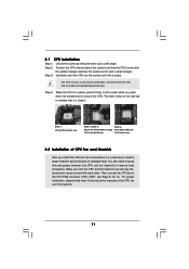
..., press it firmly on the side tab to avoid bending of the CPU fan and the heatsink. 11 Lever 90° Up Socket Corner CPU Golden Triangle STEP 1: Lift Up The Socket Lever STEP 2 / STEP 3: STEP 4: Match The CPU Golden Triangle Push Down And Lock To The Socket Corner The Socket Lever... and Heatsink After you push down the socket lever to dissipate heat. Make sure that the CPU corner with the golden triangle matches the socket corner with each other. The CPU fits only in place. When the CPU is in good contact with a small triangle. Step 4. You also need to spray thermal...
..., press it firmly on the side tab to avoid bending of the CPU fan and the heatsink. 11 Lever 90° Up Socket Corner CPU Golden Triangle STEP 1: Lift Up The Socket Lever STEP 2 / STEP 3: STEP 4: Match The CPU Golden Triangle Push Down And Lock To The Socket Corner The Socket Lever... and Heatsink After you push down the socket lever to dissipate heat. Make sure that the CPU corner with the golden triangle matches the socket corner with each other. The CPU fits only in place. When the CPU is in good contact with a small triangle. Step 4. You also need to spray thermal...
User Manual
Page 13
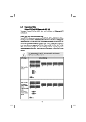
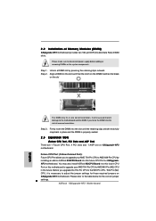
... to AMD 939-Pin CPU by installing an add-on ASRock 939CPU Board into this future CPU Port on this future CPU Port on K8Upgrade-NF3 motherboard. Future CPU Port (Yellow-Colored Port): Future CPU Port allows you upgrade the 754-Pin CPU to the 939-Pin CPU / 940-Pin (M2) CPU, it ! You may also install ASRock M2CPU Board into this...
... to AMD 939-Pin CPU by installing an add-on ASRock 939CPU Board into this future CPU Port on this future CPU Port on K8Upgrade-NF3 motherboard. Future CPU Port (Yellow-Colored Port): Future CPU Port allows you upgrade the 754-Pin CPU to the 939-Pin CPU / 940-Pin (M2) CPU, it ! You may also install ASRock M2CPU Board into this...

User Manual
Page 18
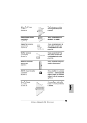
...header accommodates several system front panel functions. Please connect the chassis speaker to the ground pin. GND +12V CPU_FAN_SPEED Please connect the CPU fan cable to this connector and match the black wire to this header if the Game port bracket is installed. 18 Failing to... (9-pin PANEL1) (see p.8 No. 16) Chassis Speaker Header (4-pin SPEAKER 1) (see p.8 No. 15) Chassis Fan Connector (3-pin CHA_FAN1) (see p.8 No. 17) CPU Fan Connector (3-pin CPU_FAN1) (see p.8 No. 6) ATX Power Connector (20-pin ATXPWR1) (see p.8 No. 2) Please note that it is necessary to connect a power ...
...header accommodates several system front panel functions. Please connect the chassis speaker to the ground pin. GND +12V CPU_FAN_SPEED Please connect the CPU fan cable to this connector and match the black wire to this header if the Game port bracket is installed. 18 Failing to... (9-pin PANEL1) (see p.8 No. 16) Chassis Speaker Header (4-pin SPEAKER 1) (see p.8 No. 15) Chassis Fan Connector (3-pin CHA_FAN1) (see p.8 No. 17) CPU Fan Connector (3-pin CPU_FAN1) (see p.8 No. 6) ATX Power Connector (20-pin ATXPWR1) (see p.8 No. 2) Please note that it is necessary to connect a power ...

User Manual
Page 25
... Chipset Configuration ACPI Configuration IDE Configuration PCIPnP Configuration Floppy Configuration SuperIO Configuration USB Configuration Options for the following items: CPU Configuration, Chipset Configuration, ACPI Configuration, IDE Configuration, PCIPnP Configuration, Floppy Configuration, SuperIO Configuration, and USB Configuration. 3.3 Advanced Screen In this section... UTILITY Advanced H/W Monitor Boot Security Exit Advanced Settings WARNING : Setting wrong values in this section, you may set the configurations for CPU Select Screen Select Item Enter Go to malfunction. 25
... Chipset Configuration ACPI Configuration IDE Configuration PCIPnP Configuration Floppy Configuration SuperIO Configuration USB Configuration Options for the following items: CPU Configuration, Chipset Configuration, ACPI Configuration, IDE Configuration, PCIPnP Configuration, Floppy Configuration, SuperIO Configuration, and USB Configuration. 3.3 Advanced Screen In this section... UTILITY Advanced H/W Monitor Boot Security Exit Advanced Settings WARNING : Setting wrong values in this section, you may set the configurations for CPU Select Screen Select Item Enter Go to malfunction. 25

User Manual
Page 26
...This feature will be set to enable or disable AMD's Cool 'n' QuietTM technology. Multiplier/Voltage Change This item is from 50MHz to adjust CPU frequency. The range is set based on User Selection in Setup. +F1 F9 F10 ESC Select Screen Select Item Change Option General Help.... The default value is [66]. The range is [200]. Cnfiguration options: [Auto], [CPU, AGP, Sync.] and [CPU, AGP, Async.]. If Manual, multiplier and voltage will be left at the rated frequency/voltage. CPU Frequency (MHz) Use this item to [Auto] by default. The default value is from ...
...This feature will be set to enable or disable AMD's Cool 'n' QuietTM technology. Multiplier/Voltage Change This item is from 50MHz to adjust CPU frequency. The range is set based on User Selection in Setup. +F1 F9 F10 ESC Select Screen Select Item Change Option General Help.... The default value is [66]. The range is [200]. Cnfiguration options: [Auto], [CPU, AGP, Sync.] and [CPU, AGP, Async.]. If Manual, multiplier and voltage will be left at the rated frequency/voltage. CPU Frequency (MHz) Use this item to [Auto] by default. The default value is from ...

User Manual
Page 27
... will allow better tolerance for memory compatibility when it is not recommended to adjust the value of "Processor Maximum Multiplier". Advanced BIOS SETUP UTILITY CPU Configuration Overclock Mode CPU Frequency (MHz) AGP Frequency (MHz) Boot Failure Guard Spread Spectrum Cool' n' Quiet Processor Maximum Multiplier Processor Maximum Voltage Multiplier/Voltage Change Processor Multiplier...
... will allow better tolerance for memory compatibility when it is not recommended to adjust the value of "Processor Maximum Multiplier". Advanced BIOS SETUP UTILITY CPU Configuration Overclock Mode CPU Frequency (MHz) AGP Frequency (MHz) Boot Failure Guard Spread Spectrum Cool' n' Quiet Processor Maximum Multiplier Processor Maximum Voltage Multiplier/Voltage Change Processor Multiplier...
User Manual
Page 35
Legacy USB Support Use this item to enable or disable the use of the CPU temperature, motherboard temperature, CPU fan speed, chassis fan speed, and the critical voltage. USB Controller Use this item to enable or disable the support .... 3.4 Hardware Health Event Monitoring Screen In this item to auto-detect; BIOS SETUP UTILITY Main Advanced H/W Monitor Boot Security Exit Hardware Health Event Monitoring CPU Temperature M / B Temperature CPU Fan Speed Chassis Fan Speed Vcore + 3.30V + 5.00V + 12.00V : 37 C / 98 F : 31 C / 87 F : 2833 RPM : N/A : 1.532 V : 3.129 V : 4.877 V : 11....
Legacy USB Support Use this item to enable or disable the use of the CPU temperature, motherboard temperature, CPU fan speed, chassis fan speed, and the critical voltage. USB Controller Use this item to enable or disable the support .... 3.4 Hardware Health Event Monitoring Screen In this item to auto-detect; BIOS SETUP UTILITY Main Advanced H/W Monitor Boot Security Exit Hardware Health Event Monitoring CPU Temperature M / B Temperature CPU Fan Speed Chassis Fan Speed Vcore + 3.30V + 5.00V + 12.00V : 37 C / 98 F : 31 C / 87 F : 2833 RPM : N/A : 1.532 V : 3.129 V : 4.877 V : 11....
Quick Installation Guide
Page 2
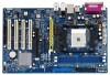
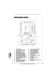
Motherboard Layout English 1 PS2_USB_PW1 Jumper 2 ATX 12V Power Connector (ATX12V1) 3 ATX Power Connector (ATXPWR1) 4 754-Pin CPU Socket 5 CPU Heatsink Retention Module 6 CPU Fan Connector (CPU_FAN1) 7 184-pin DDR DIMM Slots (DDR1- 2) 8 Secondary IDE Connector (IDE2, Black) 9 Primary IDE Connector (IDE1, Blue) 10 Primary Serial ATA Connector (SATA1) ... Slots (PCI1- 4) 25 Internal Audio Connector: CD1 (Black) 26 Flash Memory 27 Infrared Module Header (IR1) 28 J15 Jumper 29 J9 / J10 Jumper 30 Future CPU Port (FUTURE_CPU_PORT1) 31 J1-J8 Jumpers 2 ASRock K8Upgrade-NF3 Motherboard
Motherboard Layout English 1 PS2_USB_PW1 Jumper 2 ATX 12V Power Connector (ATX12V1) 3 ATX Power Connector (ATXPWR1) 4 754-Pin CPU Socket 5 CPU Heatsink Retention Module 6 CPU Fan Connector (CPU_FAN1) 7 184-pin DDR DIMM Slots (DDR1- 2) 8 Secondary IDE Connector (IDE2, Black) 9 Primary IDE Connector (IDE1, Blue) 10 Primary Serial ATA Connector (SATA1) ... Slots (PCI1- 4) 25 Internal Audio Connector: CD1 (Black) 26 Flash Memory 27 Infrared Module Header (IR1) 28 J15 Jumper 29 J9 / J10 Jumper 30 Future CPU Port (FUTURE_CPU_PORT1) 31 J1-J8 Jumpers 2 ASRock K8Upgrade-NF3 Motherboard
Quick Installation Guide
Page 4
... in Floppy Drive Ribbon Cable 1 x Serial ATA (SATA) Data Cable (Optional) 1 x Serial ATA (SATA) HDD Power Cable (Optional) 1 x ASRock 8CH I/O Shield 4 ASRock K8Upgrade-NF3 Motherboard English You may find the latest memory and CPU support lists on ASRock website without notice. Because the motherboard specifications and the BIOS software might be updated, the content of the...
... in Floppy Drive Ribbon Cable 1 x Serial ATA (SATA) Data Cable (Optional) 1 x Serial ATA (SATA) HDD Power Cable (Optional) 1 x ASRock 8CH I/O Shield 4 ASRock K8Upgrade-NF3 Motherboard English You may find the latest memory and CPU support lists on ASRock website without notice. Because the motherboard specifications and the BIOS software might be updated, the content of the...
Quick Installation Guide
Page 5
... future CPU, such as 940-Pin CPU (M2) (see page 8 for details) PCI Slots: 4 x PCI Slots, PCI Specification 2.2 AGP Slot: 1 x AGP Slot Supports 1.5V, 8X / 4X AGP Card (see CAUTION 4) USB 2.0: 8 USB 2.0 Ports: 4 Ready-to-Use USB 2.0 Ports on the I/O Panel Plus 2 On-Board Headers Supporting 4 Extra USB 2.0 Ports (see CAUTION 5) English 5 ASRock K8Upgrade-NF3...
... future CPU, such as 940-Pin CPU (M2) (see page 8 for details) PCI Slots: 4 x PCI Slots, PCI Specification 2.2 AGP Slot: 1 x AGP Slot Supports 1.5V, 8X / 4X AGP Card (see CAUTION 4) USB 2.0: 8 USB 2.0 Ports: 4 Ready-to-Use USB 2.0 Ports on the I/O Panel Plus 2 On-Board Headers Supporting 4 Extra USB 2.0 Ports (see CAUTION 5) English 5 ASRock K8Upgrade-NF3...
Quick Installation Guide
Page 6
.../PCI buses. Power Management for proper connection. 7. It may not work properly under a more stable overclocking environment. 3. English 6 ASRock K8Upgrade-NF3 Motherboard This motherboard supports Untied Overclocking Technology. During overclocking, FSB enjoys better margin due to spray thermal grease between the CPU and the heatsink when you resume the system, please check if the...
.../PCI buses. Power Management for proper connection. 7. It may not work properly under a more stable overclocking environment. 3. English 6 ASRock K8Upgrade-NF3 Motherboard This motherboard supports Untied Overclocking Technology. During overclocking, FSB enjoys better margin due to spray thermal grease between the CPU and the heatsink when you resume the system, please check if the...
Quick Installation Guide
Page 7
... or change any motherboard settings. 1. Installation Pre-installation Precautions Take note of the pins. Position the CPU directly above the socket such that the CPU corner with the golden triangle matches the socket corner with the component. 5. To avoid damaging the motherboard...strap or touch a safety grounded object before touching any component, place it fits in one correct orientation. When the CPU is locked. English 7 ASRock K8Upgrade-NF3 Motherboard Unlock the socket by the edges and do not over-tighten the screws! The lever clicks on a grounded antstatic...
... or change any motherboard settings. 1. Installation Pre-installation Precautions Take note of the pins. Position the CPU directly above the socket such that the CPU corner with the golden triangle matches the socket corner with the component. 5. To avoid damaging the motherboard...strap or touch a safety grounded object before touching any component, place it fits in one correct orientation. When the CPU is locked. English 7 ASRock K8Upgrade-NF3 Motherboard Unlock the socket by the edges and do not over-tighten the screws! The lever clicks on a grounded antstatic...
Quick Installation Guide
Page 8
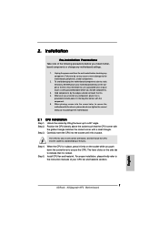
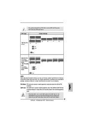
... to the table below for those required jumpers on K8Upgrade- Step 1. Please refer to adjust the jumper settings for the correct jumper settings. 8 ASRock K8Upgrade-NF3 Motherboard English Please make sure to AMD 940-Pin (M2) CPU in the future. NF3 motherboard. 2.2 Installation of Memory Modules (DIMM) K8Upgrade-NF3 motherboard provides two 184-pin DDR (Double Data Rate...
... to the table below for those required jumpers on K8Upgrade- Step 1. Please refer to adjust the jumper settings for the correct jumper settings. 8 ASRock K8Upgrade-NF3 Motherboard English Please make sure to AMD 940-Pin (M2) CPU in the future. NF3 motherboard. 2.2 Installation of Memory Modules (DIMM) K8Upgrade-NF3 motherboard provides two 184-pin DDR (Double Data Rate...
Quick Installation Guide
Page 9
This yellow-colored Future CPU Port is used to install expansion cards that can securely fasten the inserted graphics card. This Jumper Cap Remover is bundled in your AGP card, please check with the AGP card vendors. 9 ASRock K8Upgrade-NF3 Motherboard English Please do NOT insert any AGP card... into it properly. For the voltage information of this motherboard! It may use it ! PCI Slots: PCI slots are used to help you may cause permanent damage! The ASRock AGP slot has a ...
This yellow-colored Future CPU Port is used to install expansion cards that can securely fasten the inserted graphics card. This Jumper Cap Remover is bundled in your AGP card, please check with the AGP card vendors. 9 ASRock K8Upgrade-NF3 Motherboard English Please do NOT insert any AGP card... into it properly. For the voltage information of this motherboard! It may use it ! PCI Slots: PCI slots are used to help you may cause permanent damage! The ASRock AGP slot has a ...
Quick Installation Guide
Page 13
...necessary to connect a power supply with ATX 12V plug to the ground pin. Please connect the CPU fan cable to the ground pin. Failing to this header. English 13 ASRock K8Upgrade-NF3 Motherboard System Panel Header (9-pin PANEL1) (see p.2 No. 16) Chassis Speaker Header (4-pin ...SPEAKER 1) (see p.2 No. 15) Chassis Fan Connector (3-pin CHA_FAN1) (see p.2 No. 17) CPU Fan Connector (3-pin CPU_FAN1) (see p.2 No. 6) ...
...necessary to connect a power supply with ATX 12V plug to the ground pin. Please connect the CPU fan cable to the ground pin. Failing to this header. English 13 ASRock K8Upgrade-NF3 Motherboard System Panel Header (9-pin PANEL1) (see p.2 No. 16) Chassis Speaker Header (4-pin ...SPEAKER 1) (see p.2 No. 15) Chassis Fan Connector (3-pin CHA_FAN1) (see p.2 No. 17) CPU Fan Connector (3-pin CPU_FAN1) (see p.2 No. 6) ...


