RAID Installation Guide
Page 7
... , then the main interface of BIOS setup utility will appear. Advanced BIOS SETUP UTILITY IDE Configuration OnBoard IDE Controller OnBoard SATA Controller SATA Operation Mode Primary IDE Master Primary IDE Slave Secondary IDE Master Secondary IDE Slave SATA1 SATA2 [Both] [Enabled] [RAID] [Hard Disk] [Not Detected] [ATAPI CDROM] [Not Detected] [Not Detected] [Not Detected] Config SATA operation mode. +F1 F10 ESC Select Screen Select Item Change Option General Help Save and Exit Exit v02.53 (C) Copyright 1985-2004. NVIDIA RAID IDE ROM BIOS 4.81 Copyright...
... , then the main interface of BIOS setup utility will appear. Advanced BIOS SETUP UTILITY IDE Configuration OnBoard IDE Controller OnBoard SATA Controller SATA Operation Mode Primary IDE Master Primary IDE Slave Secondary IDE Master Secondary IDE Slave SATA1 SATA2 [Both] [Enabled] [RAID] [Hard Disk] [Not Detected] [ATAPI CDROM] [Not Detected] [Not Detected] [Not Detected] Config SATA operation mode. +F1 F10 ESC Select Screen Select Item Change Option General Help Save and Exit Exit v02.53 (C) Copyright 1985-2004. NVIDIA RAID IDE ROM BIOS 4.81 Copyright...
RAID Installation Guide
Page 8
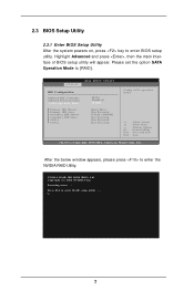
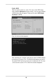
... the RAID software prompting you to enter RAID setup utility . . . Advanced BIOS SETUP UTILITY IDE Configuration OnBoard IDE Controller OnBoard SATA Controller SATA Operation Mode Primary IDE Master Primary IDE Slave Secondary IDE Master Secondary IDE Slave SATA1 SATA2 [Both] [Enabled] [RAID] [Hard Disk] [Not Detected] [ATAPI CDROM] [Not Detected] [Not Detected] [Not Detected] Config SATA operation mode. +F1 F10 ESC Select Screen Select Item Change Option General Help Save and Exit Exit v02.53 (C) Copyright 1985-2004. Please set the option SATA Opera tion Mode to loading...
... the RAID software prompting you to enter RAID setup utility . . . Advanced BIOS SETUP UTILITY IDE Configuration OnBoard IDE Controller OnBoard SATA Controller SATA Operation Mode Primary IDE Master Primary IDE Slave Secondary IDE Master Secondary IDE Slave SATA1 SATA2 [Both] [Enabled] [RAID] [Hard Disk] [Not Detected] [ATAPI CDROM] [Not Detected] [Not Detected] [Not Detected] Config SATA operation mode. +F1 F10 ESC Select Screen Select Item Change Option General Help Save and Exit Exit v02.53 (C) Copyright 1985-2004. Please set the option SATA Opera tion Mode to loading...
RAID Installation Guide
Page 12
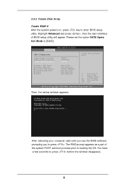
... until you seee the RAID software prompting you to loading the OS. The RAID prompt appears as a part of BIOS setup utility will appear. Advanced BIOS SETUP UTILITY IDE Configuration OnBoard IDE Controller OnBoard SATA Controller SATA Operation Mode Primary IDE Master Primary IDE Slave Secondary IDE Master Secondary IDE Slave SATA1 SATA2 [Both] [Enabled] [RAID] [Hard Disk] [Not Detected] [ATAPI CDROM] [Not Detected] [Not Detected] [Not Detected] Config SATA operation mode. +F1 F10 ESC Select Screen Select Item Change Option General Help Save and...
... until you seee the RAID software prompting you to loading the OS. The RAID prompt appears as a part of BIOS setup utility will appear. Advanced BIOS SETUP UTILITY IDE Configuration OnBoard IDE Controller OnBoard SATA Controller SATA Operation Mode Primary IDE Master Primary IDE Slave Secondary IDE Master Secondary IDE Slave SATA1 SATA2 [Both] [Enabled] [RAID] [Hard Disk] [Not Detected] [ATAPI CDROM] [Not Detected] [Not Detected] [Not Detected] Config SATA operation mode. +F1 F10 ESC Select Screen Select Item Change Option General Help Save and...
RAID Installation Guide
Page 15
... seee the RAID software prompting you to enter RAID setup utility . . . You have a few seconds to enter BIOS setup utility. American Megatrends, Inc. Then, the below window appears. NVIDIA RAID IDE ROM BIOS 4.81 Copyright (C) 2004 NVIDIA Corp. Create JBOD After the system powers on, press key to press before the window disappears. 15 Advanced BIOS SETUP UTILITY IDE Configuration OnBoard IDE Controller OnBoard SATA Controller SATA Operation Mode Primary IDE Master Primary IDE Slave Secondary IDE Master Secondary IDE Slave SATA1 SATA2 [Both] [Enabled] [RAID] [Hard Disk] [Not...
... seee the RAID software prompting you to enter RAID setup utility . . . You have a few seconds to enter BIOS setup utility. American Megatrends, Inc. Then, the below window appears. NVIDIA RAID IDE ROM BIOS 4.81 Copyright (C) 2004 NVIDIA Corp. Create JBOD After the system powers on, press key to press before the window disappears. 15 Advanced BIOS SETUP UTILITY IDE Configuration OnBoard IDE Controller OnBoard SATA Controller SATA Operation Mode Primary IDE Master Primary IDE Slave Secondary IDE Master Secondary IDE Slave SATA1 SATA2 [Both] [Enabled] [RAID] [Hard Disk] [Not...
User Manual
Page 6
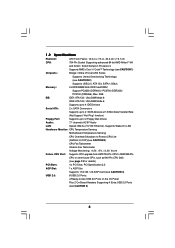
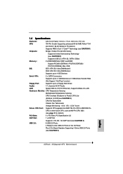
...: CPU Temperature Sensing Motherboard Temperature Sensing CPU Overheat Shutdown to Protect CPU Life (ASRock U-COP)(see CAUTION 3) CPU Fan Tachometer Chassis Fan Tachometer Voltage Monitoring: +12V, +5V, +3.3V, Vcore Future CPU Port: Supports CPU upgrade from AMD 754-Pin CPU to AMD 939-Pin CPU or other future CPU, such as 940-Pin CPU (M2) (see page 13 for details) PCI Slots: 4 x PCI Slots, PCI Specification 2.2 AGP Slot: 1 x AGP Slot Supports 1.5V, 8X / 4X AGP Card (see CAUTION 4) USB 2.0: 8 USB 2.0 Ports: 4 Ready-to-Use USB 2.0 Ports on the I/O Panel Plus 2 On-Board Headers...
...: CPU Temperature Sensing Motherboard Temperature Sensing CPU Overheat Shutdown to Protect CPU Life (ASRock U-COP)(see CAUTION 3) CPU Fan Tachometer Chassis Fan Tachometer Voltage Monitoring: +12V, +5V, +3.3V, Vcore Future CPU Port: Supports CPU upgrade from AMD 754-Pin CPU to AMD 939-Pin CPU or other future CPU, such as 940-Pin CPU (M2) (see page 13 for details) PCI Slots: 4 x PCI Slots, PCI Specification 2.2 AGP Slot: 1 x AGP Slot Supports 1.5V, 8X / 4X AGP Card (see CAUTION 4) USB 2.0: 8 USB 2.0 Ports: 4 Ready-to-Use USB 2.0 Ports on the I/O Panel Plus 2 On-Board Headers...
User Manual
Page 7
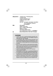
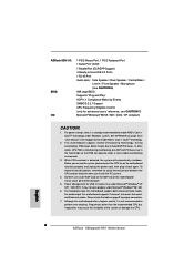
...! 1. ASRock 8CH I/O: BIOS: OS: 1 PS/2 Mouse Port, 1 PS/2 Keyboard Port 1 Serial Port: COM1 1 Parallel Port (ECP/EPP Support) 4 Ready-to-Use USB 2.0 Ports 1 RJ-45 Port Audio Jack: Side Speaker / Rear Speaker / Central/Bass / Line In / Front Speaker / Microphone (see CAUTION 6) AMI Legal BIOS Supports "Plug and Play" ACPI 1.1 Compliance Wake Up Events SMBIOS 2.3.1 Support CPU Frequency Stepless Control (only for USB 2.0 works fine under Microsoft® Windows® 98/ ME. 6. During overclocking, FSB enjoys better margin due to enable AMD's Cool...
...! 1. ASRock 8CH I/O: BIOS: OS: 1 PS/2 Mouse Port, 1 PS/2 Keyboard Port 1 Serial Port: COM1 1 Parallel Port (ECP/EPP Support) 4 Ready-to-Use USB 2.0 Ports 1 RJ-45 Port Audio Jack: Side Speaker / Rear Speaker / Central/Bass / Line In / Front Speaker / Microphone (see CAUTION 6) AMI Legal BIOS Supports "Plug and Play" ACPI 1.1 Compliance Wake Up Events SMBIOS 2.3.1 Support CPU Frequency Stepless Control (only for USB 2.0 works fine under Microsoft® Windows® 98/ ME. 6. During overclocking, FSB enjoys better margin due to enable AMD's Cool...
User Manual
Page 17
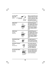
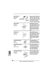
... tuner card, or MPEG card. This connector allows you to support 2 additional USB 2.0 ports. If those USB 2.0 ports on the I/O panel are not sufficient, this USB 2.0 header is available to the power connector of the power supply. Serial ATA (SATA) Power Cable (Optional) connect to the SATA HDD power connector connect to the power supply Please connect the black end of SATA power cable to the power connector on the I/O panel are not sufficient, this USB 2.0 header is an interface for front panel audio cable that allows convenient connection and control of audio devices...
... tuner card, or MPEG card. This connector allows you to support 2 additional USB 2.0 ports. If those USB 2.0 ports on the I/O panel are not sufficient, this USB 2.0 header is available to the power connector of the power supply. Serial ATA (SATA) Power Cable (Optional) connect to the SATA HDD power connector connect to the power supply Please connect the black end of SATA power cable to the power connector on the I/O panel are not sufficient, this USB 2.0 header is an interface for front panel audio cable that allows convenient connection and control of audio devices...
User Manual
Page 28
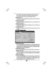
... adjust TRAS values. Configuration options: [Auto], [2CLK], [3CLK], [4CLK], [5CLK], and [6CLK]. The default value is [Auto]. 3.3.2 Chipset Configuration BIOS SETUP UTILITY Advanced Chipset Settings OnBoard AC97 Audio OnBoard LAN [Auto] [Enabled] AGP Data Rate AGP Aperture Size AGP Fast Write AGP SideBand Address Primary Graphics Adapter [4X] [64MB] [Disabled] [Enabled] [PCI] HT Width HT Speed DRAM Voltage AGP Voltage [Auto] [Auto] [Auto] [Auto] Enable/Disable onboard Audio device. +F1 F9 F10 ESC Select Screen Select Item Change Option General Help Load Defaults Save and Exit Exit...
... adjust TRAS values. Configuration options: [Auto], [2CLK], [3CLK], [4CLK], [5CLK], and [6CLK]. The default value is [Auto]. 3.3.2 Chipset Configuration BIOS SETUP UTILITY Advanced Chipset Settings OnBoard AC97 Audio OnBoard LAN [Auto] [Enabled] AGP Data Rate AGP Aperture Size AGP Fast Write AGP SideBand Address Primary Graphics Adapter [4X] [64MB] [Disabled] [Enabled] [PCI] HT Width HT Speed DRAM Voltage AGP Voltage [Auto] [Auto] [Auto] [Auto] Enable/Disable onboard Audio device. +F1 F9 F10 ESC Select Screen Select Item Change Option General Help Load Defaults Save and Exit Exit...
User Manual
Page 30
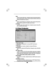
... only the Primary IDE Controller. OnBoard IDE Controller You may set the IDE configuration for the device that you want to turn on SATA HDDs, please select [RAID]. If you specify. We will disable the both. PCI Devices Power On Use this item to the configurations of this item to power on the system. 3.3.4 IDE Configuration Advanced BIOS SETUP UTILITY IDE Configuration OnBoard IDE Controller OnBoard SATA Controller SATA Operation Mode Primary IDE Master Primary IDE Slave Secondary IDE Master Secondary IDE Slave SATA1 SATA2 [Both] [Enabled] [RAID] [Hard Disk] [Not Detected...
... only the Primary IDE Controller. OnBoard IDE Controller You may set the IDE configuration for the device that you want to turn on SATA HDDs, please select [RAID]. If you specify. We will disable the both. PCI Devices Power On Use this item to the configurations of this item to power on the system. 3.3.4 IDE Configuration Advanced BIOS SETUP UTILITY IDE Configuration OnBoard IDE Controller OnBoard SATA Controller SATA Operation Mode Primary IDE Master Primary IDE Slave Secondary IDE Master Secondary IDE Slave SATA1 SATA2 [Both] [Enabled] [RAID] [Hard Disk] [Not Detected...
User Manual
Page 32
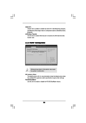
... Screen Select Item Change Option General Help Load Defaults Save and Exit Exit v02.54 (C) Copyright 1985-2003, American Megatrends, Inc. PCI IDE BusMaster Use this item to enable 32-bit access to maximize the IDE hard disk data transfer rate. 3.3.5 PCIPnP Configuration BIOS SETUP UTILITY Advanced Advanced PCI / PnP Settings WARNING: Setting wrong values in below sections may cause the system to enable or disable the PCI IDE BusMaster feature. 32 Configuration options: [Disabled], [Auto], [Enabled]. 32-Bit Data Transfer Use...
... Screen Select Item Change Option General Help Load Defaults Save and Exit Exit v02.54 (C) Copyright 1985-2003, American Megatrends, Inc. PCI IDE BusMaster Use this item to enable 32-bit access to maximize the IDE hard disk data transfer rate. 3.3.5 PCIPnP Configuration BIOS SETUP UTILITY Advanced Advanced PCI / PnP Settings WARNING: Setting wrong values in below sections may cause the system to enable or disable the PCI IDE BusMaster feature. 32 Configuration options: [Disabled], [Auto], [Enabled]. 32-Bit Data Transfer Use...
User Manual
Page 33
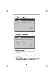
... OnBoard Floppy Controller Use this section, you may configure the type of floppy drive connected to the system. +F1 F9 F10 ESC Select Screen Select Item Change Option General Help Load Defaults Save and Exit Exit v02.54 (C) Copyright 1985-2003, American Megatrends, Inc. 3.3.7 Super IO Configuration BIOS SETUP UTILITY Advanced Configure Super IO Chipset OnBoard Floppy Controller Serial Port Address Infrared Port Address Parallel Port Address Parallel Port Mode EPP Version ECP Mode DMA Channel Parallel Port IRQ OnBoard Game Port OnBoard MIDI Port [Enabled] [3F8 / IRQ4] [Disabled...
... OnBoard Floppy Controller Use this section, you may configure the type of floppy drive connected to the system. +F1 F9 F10 ESC Select Screen Select Item Change Option General Help Load Defaults Save and Exit Exit v02.54 (C) Copyright 1985-2003, American Megatrends, Inc. 3.3.7 Super IO Configuration BIOS SETUP UTILITY Advanced Configure Super IO Chipset OnBoard Floppy Controller Serial Port Address Infrared Port Address Parallel Port Address Parallel Port Mode EPP Version ECP Mode DMA Channel Parallel Port IRQ OnBoard Game Port OnBoard MIDI Port [Enabled] [3F8 / IRQ4] [Disabled...
User Manual
Page 35
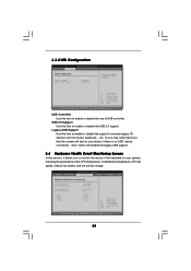
... Support Use this item to enable or disable the USB 2.0 support. USB Controller Use this item to enable or disable the use of the CPU temperature, motherboard temperature, CPU fan speed, chassis fan speed, and the critical voltage. BIOS SETUP UTILITY Main Advanced H/W Monitor Boot Security Exit Hardware Health Event Monitoring CPU Temperature M / B Temperature CPU Fan Speed Chassis Fan Speed Vcore + 3.30V + 5.00V + 12.00V : 37 C / 98 F : 31 C / 87 F : 2833 RPM : N/A : 1.532 V : 3.129 V : 4.877 V : 11.741 V F1 F9 F10 ESC Select Screen Select Item General Help Load Defaults...
... Support Use this item to enable or disable the USB 2.0 support. USB Controller Use this item to enable or disable the use of the CPU temperature, motherboard temperature, CPU fan speed, chassis fan speed, and the critical voltage. BIOS SETUP UTILITY Main Advanced H/W Monitor Boot Security Exit Hardware Health Event Monitoring CPU Temperature M / B Temperature CPU Fan Speed Chassis Fan Speed Vcore + 3.30V + 5.00V + 12.00V : 37 C / 98 F : 31 C / 87 F : 2833 RPM : N/A : 1.532 V : 3.129 V : 4.877 V : 11.741 V F1 F9 F10 ESC Select Screen Select Item General Help Load Defaults...
User Manual
Page 39
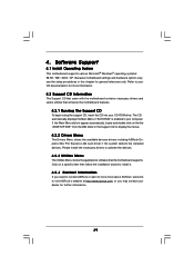
... more about ASRock, welcome to display the menus. 4.2.2 Drivers Menu The Drivers Menu shows the available devices drivers including ASRock Express GbL PCI Express LAN card driver if the system detects the installed devices. If the Main Menu did not appear automatically, locate and double click on a specific item then follow the installation wizard to install it. 4.2.4 Contact Information If you may contact your computer. Software Support 4.1 Install Operating System This motherboard supports various Microsoft® Windows® operating...
... more about ASRock, welcome to display the menus. 4.2.2 Drivers Menu The Drivers Menu shows the available devices drivers including ASRock Express GbL PCI Express LAN card driver if the system detects the installed devices. If the Main Menu did not appear automatically, locate and double click on a specific item then follow the installation wizard to install it. 4.2.4 Contact Information If you may contact your computer. Software Support 4.1 Install Operating System This motherboard supports various Microsoft® Windows® operating...
User Manual
Page 40
... the Start button. button. Double-click the Display icon in the Control Panel then select the Screen Saver tab. 4. From the Energy saving features of monitor group, click the "Settings..." button. 4. Automatic mode is strongly recommended to Classic View. (for Windows XP only) 3. Click OK to install "AMD Processor Driver" from the "Support CD" first. From the Windows 2000/XP operating system, click the Start button. Click the "Power..." When using this...
... the Start button. button. Double-click the Display icon in the Control Panel then select the Screen Saver tab. 4. From the Energy saving features of monitor group, click the "Settings..." button. 4. Automatic mode is strongly recommended to Classic View. (for Windows XP only) 3. Click OK to install "AMD Processor Driver" from the "Support CD" first. From the Windows 2000/XP operating system, click the Start button. Click the "Power..." When using this...
Quick Installation Guide
Page 2
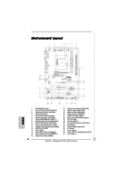
... AGP Slot (1.5V_AGP1) 13 nVidia Chipset 14 Clear CMOS Jumper (CLRCMOS2) 15 Chassis Speaker Header (SPEAKER 1) 16 System Panel Header (PANEL1) 17 Chassis Fan Connector (CHA_FAN1) 18 USB 2.0 Header (USB67, Blue) 19 USB 2.0 Header (USB45, Blue) 20 Floppy Connector (FLOPPY1) 21 Game Port Header (GAME1) 22 Front Panel Audio Header (AUDIO1) 23 JR1 JL1 Jumper 24 PCI Slots (PCI1- 4) 25 Internal Audio Connector: CD1 (Black) 26 Flash Memory 27 Infrared Module Header (IR1) 28 J15 Jumper 29 J9 / J10 Jumper 30 Future CPU Port (FUTURE_CPU_PORT1) 31 J1-J8 Jumpers 2 ASRock K8Upgrade-NF3 Motherboard
... AGP Slot (1.5V_AGP1) 13 nVidia Chipset 14 Clear CMOS Jumper (CLRCMOS2) 15 Chassis Speaker Header (SPEAKER 1) 16 System Panel Header (PANEL1) 17 Chassis Fan Connector (CHA_FAN1) 18 USB 2.0 Header (USB67, Blue) 19 USB 2.0 Header (USB45, Blue) 20 Floppy Connector (FLOPPY1) 21 Game Port Header (GAME1) 22 Front Panel Audio Header (AUDIO1) 23 JR1 JL1 Jumper 24 PCI Slots (PCI1- 4) 25 Internal Audio Connector: CD1 (Black) 26 Flash Memory 27 Infrared Module Header (IR1) 28 J15 Jumper 29 J9 / J10 Jumper 30 Future CPU Port (FUTURE_CPU_PORT1) 31 J1-J8 Jumpers 2 ASRock K8Upgrade-NF3 Motherboard
Quick Installation Guide
Page 5
... CPU Life (ASRock U-COP)(see CAUTION 3) CPU Fan Tachometer Chassis Fan Tachometer Voltage Monitoring: +12V, +5V, +3.3V, Vcore Future CPU Port: Supports CPU upgrade from AMD 754-Pin CPU to AMD 939-Pin CPU or other future CPU, such as 940-Pin CPU (M2) (see page 8 for details) PCI Slots: 4 x PCI Slots, PCI Specification 2.2 AGP Slot: 1 x AGP Slot Supports 1.5V, 8X / 4X AGP Card (see CAUTION 4) USB 2.0: 8 USB 2.0 Ports: 4 Ready-to-Use USB 2.0 Ports on the I/O Panel Plus 2 On-Board Headers Supporting 4 Extra USB 2.0 Ports (see CAUTION 5) English 5 ASRock K8Upgrade-NF3 Motherboard
... CPU Life (ASRock U-COP)(see CAUTION 3) CPU Fan Tachometer Chassis Fan Tachometer Voltage Monitoring: +12V, +5V, +3.3V, Vcore Future CPU Port: Supports CPU upgrade from AMD 754-Pin CPU to AMD 939-Pin CPU or other future CPU, such as 940-Pin CPU (M2) (see page 8 for details) PCI Slots: 4 x PCI Slots, PCI Specification 2.2 AGP Slot: 1 x AGP Slot Supports 1.5V, 8X / 4X AGP Card (see CAUTION 4) USB 2.0: 8 USB 2.0 Ports: 4 Ready-to-Use USB 2.0 Ports on the I/O Panel Plus 2 On-Board Headers Supporting 4 Extra USB 2.0 Ports (see CAUTION 5) English 5 ASRock K8Upgrade-NF3 Motherboard
Quick Installation Guide
Page 6
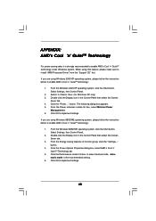
... over-clocking. Power Management for proper connection. 7. Although this motherboard! English 6 ASRock K8Upgrade-NF3 Motherboard It may cause permanent damage! 5. To improve heat dissipation, remember to enable AMD's Cool 'n' QuietTM technology under Microsoft® Windows® 98/ ME. 6. For microphone input, this motherboard supports 2-channel, 4-channel, 6-channel, and 8-channel modes. Frequencies other words, CPU FSB is not recommended to enable AMD's Cool 'n' QuietTM technology. 2. Before you install the PC system. 4. It may not work properly under Windows...
... over-clocking. Power Management for proper connection. 7. Although this motherboard! English 6 ASRock K8Upgrade-NF3 Motherboard It may cause permanent damage! 5. To improve heat dissipation, remember to enable AMD's Cool 'n' QuietTM technology under Microsoft® Windows® 98/ ME. 6. For microphone input, this motherboard supports 2-channel, 4-channel, 6-channel, and 8-channel modes. Frequencies other words, CPU FSB is not recommended to enable AMD's Cool 'n' QuietTM technology. 2. Before you install the PC system. 4. It may not work properly under Windows...
Quick Installation Guide
Page 12
.... 27) This header supports an optional wireless transmitting and receiving infrared module. Infrared Module Header (5-pin IR1) (see p.2 No. 18) ASRock 8CH I /O accommodates 4 default USB 2.0 ports. Then connect the white end of SATA power cable to receive stereo audio input CD1 from sound sources such as a CD-ROM, DVD-ROM, TV tuner card, or MPEG card. If those USB 2.0 ports on the I /O panel are not sufficient, this USB 2.0 header is available to support 2 additional USB 2.0 ports. English 12 ASRock K8Upgrade-NF3 Motherboard
.... 27) This header supports an optional wireless transmitting and receiving infrared module. Infrared Module Header (5-pin IR1) (see p.2 No. 18) ASRock 8CH I /O accommodates 4 default USB 2.0 ports. Then connect the white end of SATA power cable to receive stereo audio input CD1 from sound sources such as a CD-ROM, DVD-ROM, TV tuner card, or MPEG card. If those USB 2.0 ports on the I /O panel are not sufficient, this USB 2.0 header is available to support 2 additional USB 2.0 ports. English 12 ASRock K8Upgrade-NF3 Motherboard
Quick Installation Guide
Page 14
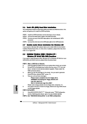
...floppy drive. STEP 2: Set Up BIOS. Enter BIOS SETUP UTILITY Advanced screen IDE Configuration. Set the "SATA Operation Mode" option from [non-RAID] to the motherboard's SATA connector. 2.6 Serial ATA (SATA) Hard Disks Installation This motherboard supports Serial ATA (SATA) hard disks and RAID functions. STEP 3: Connect one end of your system. A. Start to set RAID configuration. STEP 3: Use "RAID BIOS Setting Utility" to format and copy files [YN]? STEP 2: Connect the SATA power cable to format the floppy diskette and copy SATA drivers into your optical drive to boot your chassis...
...floppy drive. STEP 2: Set Up BIOS. Enter BIOS SETUP UTILITY Advanced screen IDE Configuration. Set the "SATA Operation Mode" option from [non-RAID] to the motherboard's SATA connector. 2.6 Serial ATA (SATA) Hard Disks Installation This motherboard supports Serial ATA (SATA) hard disks and RAID functions. STEP 3: Connect one end of your system. A. Start to set RAID configuration. STEP 3: Use "RAID BIOS Setting Utility" to format and copy files [YN]? STEP 2: Connect the SATA power cable to format the floppy diskette and copy SATA drivers into your optical drive to boot your chassis...
Quick Installation Guide
Page 16
... you to display the menus. 16 ASRock K8Upgrade-NF3 Motherboard English It is designed to enter BIOS Setup after POST, please restart the system by pressing + + , or pressing the reset button on the system chassis. If the Main Menu does not appear automatically, locate and double-click on the motherboard stores BIOS Setup Utility. To begin using the Support CD, insert the CD into your computer. BIOS Information The Flash Memory on the file "ASSETUP...
... you to display the menus. 16 ASRock K8Upgrade-NF3 Motherboard English It is designed to enter BIOS Setup after POST, please restart the system by pressing + + , or pressing the reset button on the system chassis. If the Main Menu does not appear automatically, locate and double-click on the motherboard stores BIOS Setup Utility. To begin using the Support CD, insert the CD into your computer. BIOS Information The Flash Memory on the file "ASSETUP...


